Design of Fuel Efficient Brick Kiln for Ceramic Water Filter Firing in Ghana
by
Eric Adjorlolo and Silpa Kaza
SUBMITTED TO THE DEPARTMENT OF MECHANICAL ENGINEERING IN
PARTIAL FULFILLMENT OF THE REQUIREMENTS FOR THE DEGREE OF
BACHELOR OF SCIENCE
AT THE
MASSACHUSETTS INSTITUTE OF TECHNOLOGY
JUNE 2007
© Eric Adjorlolo and Silpa Kaza. All rights reserved.
The authors hereby grant to MIT permission to reproduce
and to distribute publicly paper and electronic
copies of this thesis document in whole or in part
in any medium now known or hereafter created.
Signatures of Authors:
___
_
__
I/-
I
Dep•rtment of Mechanical Engineering
5/15/2007
Certified by:
Accepted by:
I - --Susan Murcott
Senior Lecturer
Thesis Supervisor
John H. Lienhard V
Professor of Mechanical Engineering
Chairman, Undergraduate Thesis Committee
ARCHiVES
MASSACHUSETTS INSTITUTE OF TECHNOLOGYJUN 2
1
2007
LIBRARIES
• IL Nr .man-qDesign of Fuel Efficient Brick Kiln for Ceramic Water Filter Firing in Ghana
by
Eric Adjorlolo and Silpa Kaza
Submitted to the Department of Mechanical Engineering
on May 11, 2007 in Partial Fulfillment of the
Requirements for the Degree of Master of Science in
Mechanical Engineering.
ABSTRACT
Ceramic water filters are currently produced in Ghana in order to provide a
household solution to contaminated water. These filters, locally branded with the
name Kosim filter by originating from Potters for Peace-Nicaragua, are heated
using a generic kiln that is not attuned to the filters' current characteristics. The
need for water filters is currently greatest in Northern Ghana, where more than one
million people do not have access to safe water, but filter production occurs in
Southern Ghana. A custom kiln will strengthen the filters, increase the filter's
survival rate, and eliminate the need to transport the filters. Additionally, the
traditional fuel source, wood, is extremely scarce, thus indicating the need for a
more fuel efficient method of firing the kiln. Our thesis focuses on evaluating
prior kilns built in developing countries and designing a fuel efficient kiln for
Northern Ghana, where a kiln does not currently exist and fuel is scarce.
Thesis Supervisor: Susan Murcott
Title: Senior Lecturer
Acknowledgements:
Susan Murcott, Senior Lecturer at MIT and Head of Pure Home Water Frederick L. Olsen, Author of The Kiln Book.
Daniel Rhodes, Author of Kilns: Design. Construction and Operation. Ron Rivera, Potters for Peace Coordinator in Nicaragua
Peter Tamakloe, Owner of Ceramica Tamakloe
Darrel Dinnagen, Pottery Instructor at MIT's Student Art Association Dean Kim VanDiver, Dean at MIT
Reid Harvey, Owner of Silver Ceramics Systems Jason Manto, Member of Cameroon Water Filter Team Navid Rahimi
Elizabeth Wood, Pure Home Water
Lynn Gervens, Pottery Instructor at Mudflat Robert Marquez, PhD in Mechanical Engineering
Table of Contents
1. Introduction 13
1.1 Water
1.1.1 Safe Water and Sanitation 1.1.2 Ghana
1.1.3 Pure Home Water
1.1.4 Improving Manufacturing Process
1.2 Deforestation
2.
Kilns
17
2.1 General Kiln Description
2.2 Downdraft Kiln
2.2.1 Basic Components of a Downdraft Kiln 2.2.2 Firebox
2.2.3 Chimney
2.2.4 Advantages and Concerns
2.3 Updraft Kilns
2.3.1 Basic Components of an Updraft Kiln 2.3.2 Air Flow
2.3.3 Advantages and Concerns 2.4 Alternative Kiln
3.
Design of Kiln
26
3.1 Selecting Type of Kiln
3.1.1 Land Area
3.1.2 Fuel Efficiency
3.1.3 Temperature Distribution
3.3 Firebox
3.4 Exit From Chamber 3.5 Chimney 3.6 Fuels 3.6.1 Oil 3.6.2 Coal 3.6.3 Natural Gas 3.6.4 Wood 3.6.5 Alternative Fuel 3.7 Materials 3.7.1 Bricks 3.7.2 Mortars 3.7.3 Iron 3.8 Wall Design 3.9 Recuperation Designs
3.9.1 Recuperation Design Utilizing Power
3.9.2 Recuperation Design Without Power
4. Thermodynamics 41
4.1 Model Description
4.1.1 Temperature Distribution of Overall Kiln
4.2 Heat Transfer 4.2.1 Combustion 4.2.2 Convection 4.2.3 Radiation 4.2.4 Conduction 4.3 Air Flow 4.4 Thermodynamics 4.4.1 Temperature Distribution
4.4.2 Thermal Resistance 4.4.3 Combustion
4.4.4 Walls and Bagwall 4.4.5 Arch
4.4.6 Filters
4.4.7 Heat Exchanger: Recuperating Air with a Blower
5.
Firing Information
57
5.1 Firing the Kiln
5.1.1 Beginning the Fire 5.1.2 Main Firing Phase
5.1.3 Cooling the Kiln
5.2 Measuring Temperature in the Kiln
5.3 Time Range
5.4 Final Filter Characteristics
5.4.1 Expected Performance Qualities 5.4.2 Absorption and Filtration Rates 5.4.3 Porosity
5.4.4 Physical Appearance
6.
Building the Kiln
63
6.1 Materials 6.1.1 Bricks
6.1.1a Common Brick 6.1.1b Keybrick 6.1.2 Angle Iron 6.1.3 Mild Steel Pipe 6.1.4 Additional Materials
6.2.1 Bricklaying Techniques 6.2.1a Header Course
6.2.1b Stretcher Course 6.2.2 Foundation 6.2.3 Flues 6.2.4 Walls 6.2.5 Arch 6.2.6 Insulation 6.2.7 Chimney
6.3 Building the Kiln Step by Step
6.3.1 Heat Exchanger 6.3.2 Foundation 6.3.3 Floor Flues
6.3.4 Bagwalls and Floor 6.3.5 Frame 6.3.6 Firebox 6.3.7 Side Flues 6.3.8 Door 6.3.9 Back Wall 6.3.10 Arch 6.3.11 Heat Exchanger 6.3.12 Chimney
6.4 Evaluating the Kiln and Filters
Appendices
89
1.
Introduction
1.1 Water
1.1.1 Safe Water and Sanitation
The need for safe water and sanitation is urgent throughout the world; the World Health Organization (WHO) estimates that in 2004, 1.1 billion people lacked access to an improved water source globally, as shown by percentage of population without access in Figure 1.
Additionally, over 2.6 billion people did not have access to basic sanitation (WHO, 2004). There are 1.7 million deaths annually related to water diseases, 90 percent of whom are children under
5 years of age. The United Nations Millennium Development Goals (MDGs) include the objective of halving the proportion of people without access to safe drinking water and basic sanitation by 2015 (U.N. MDGs, 2004). So far, sanitation coverage increased from 35 to 50 percent from 1990 to 2004 (MDG Report, 2006). While water coverage had risen to 80 percent
by 2004 in the developing world, populations continue to grow and disparities in wealth persist. By improving water access and basic sanitation, the world would greatly reduce the number of
deaths.
Percent of population wihout access
= No data 26% - 50%
51% - 75%
76%.- 100%
Populations without access to safe drinking water
frorn The World's WaterThe Biennial Report on Freshwater Resources (Gleick 1998)
Figure 1. Populations without access to safe drinking water. Courtesy of The World's Water.
1.1.2 Ghana
Ghana is a country located on the coast of West Africa and is bordered by the Gulf of Guinea, Cote D'Ivoire, Burkina Faso, and Togo. Improved water sources, and access to them, are rare in the northern region of Ghana. For this reason, the thesis will focus on this region, and more
specifically, the district capital of the Northern Region, Tamale. The organization we are working with, Pure Home Water, has already established a need for water filters and a market to purchase them. The population in Tamale is approximately 280,000 people, and the population in the Northern region generally, which is Pure Home Water's target region, is 1.8 million. The implication of local production of these ceramic water filters is significant.'
Figure 2. Map of Ghana. Tamale is highlighted with a red oval. Courtesy of Susan Murcott.
In 2000, 64 percent of Ghanaians had access to safe drinking water, with most of them being located in the southern and urban regions (WHO, 2000). 87 percent of the urban areas had access to safe drinking water while only 49 percent of rural Ghana did (WHO, 2000). It is imperative to improve the safe water in the Northern part of Ghana, one by one.
1.1.3 Pure Home Water
Pure Home Water (PHW) is a social enterprise that sells safe household water treatment and storage technologies. It began as an MIT initiative led by Susan Murcott, Senior Lecturer in the Civil and Environmental Engineering Department with two year support from the Conrad N. Hilton Foundation, and has grown to collaborate with several local NGO partners in Ghana, including World Vision -Ghana, Enterprise Works to achieve a greater distribution. Thus far, PHW has purchased the filters from a manufacturer, Ceramica Tamakloe Limited, in Southern Ghana and distributed them 640 km away in Northern Ghana. The team has been successful in creating demand for this filter from middle and low income families; the next step is to bring the manufacturing process to the North in order to reduce the price and improve the manufacturing process, in order to reach the maximum number of people.
1.1.4 Improving Manufacturing Process
Currently the enterprise outsources the manufacturing in Accra, Ghana, the nation's capital. This has resulted in numerous issues, including the use of nonspecific kilns, nonideal firing methods, 10-12 hour road transport to the North, high filter breakage, inflated price, and dependence on a single manufacturer and unreliable transporters. These problems can be solved wiht the
decision, by Pure Home Water, to commence manufacturing their own filters in the Northern Region. One key aspect of local manufacture is the availability of an improved kiln in Tamale itself. A kiln in Tamale will reduce travel time, ensure stronger filters because of a higher firing temperature, eliminate the middle man, reduce costs, and empower the people in the Northern region of Ghana to treat their water with a locally produced product.
1.2 Deforestation
Deforestation is a major problem in Ghana. It is relevant to our thesis, because wood is the fuel of choice for kilns in Ghana, and it is important to get good fuel efficiency in order to save as much wood as possible. With a fuel-efficient kiln, wood use can be cut down, leaving more for other purposes. The wood scarcity issue is not specifically covered in our thesis, but is an issue to take into account.
Timber is one of the country's largest exports, and the tropical rain forest in Southern Ghana has suffered greatly as a result because of this industry. In fact, the size of the rain forest in Ghana is only 25 percent of what it used to be2. Trees are also cleared away in order to make room for
Ghana's chief export, cocoa. Despite efforts to control the loss of the forests, the policies put in place by the Ghanaian government have not been effective, and much of the actual tree is wasted during the processing phase.
In the Northern Region, where the kiln will be constructed, a different type of forest exists: the Guinea Savannah Woodland, which consists of acacia, baobab, and shea trees. Deforestation is also a problem in this region, as trees are cut down in order to make room for farmland for pastures and to produce firewood. As in the Southern region, the Northern region is also
suffering because of deforestation. Only 15% of the northern, savanna forests are protected from use. Because producing charcoal and firewood is an income earner in this area, wood is being cut
down and not replaced at a sustainable level.3
According to one study, 55 percent of the log that is processed becomes waste.4 Currently, only
16 percent of the forests have been placed in a reserve, leaving most of the forest to be cut down.5 Despite all the bans and policies to try and protect the Ghanaian forests, "evidence shows that deforestation in Ghana has not declined"6
2
TED Case Studies: Ghana Forest Loss. http://www.american.edu/TED/ghana.htm
'Food and Agricultural Organization of the United Nations. "Forest Genetic Resources Working Papers." ftp://ftp.fao.org/docrep/fao/004/AB388E/AB388E00.pdf
4Derzu, Dominic, Mensah-Browh, Henry, Brew-Hammond Abeeku. "Wood Waste Cogeneration in Kumasi, Ghana." In Bioenergy - Realizing the Potential, edited by Semida Silveira, 214. Amsterdam: Elsevier, 2005.
5TED Case Studies: Ghana Forest Loss. http://www.american.edu/TED/ghana.htm
6
Figure 3: Sawdust waste from a wood processing facility in Ghana.7
"The elimination of forest cover sets in motion a chain of devastating ecological consequences that accelerate soil degradation and erosion, eliminate wildlife habitats, and lead to the loss of bio-diversity".8 The destruction of the soil causes major issues for the local population as they have less land to farm and more water gets contaminated with dust and soil runoff. Vegetation protects water sources, for it covers water, preventing evaporation, and slows the erosion of soil
by making it less likely to blow around in the winds and fall into water.9 Trees are already sparse in the Northern region of Ghana, which is a semi-arid climate. As more trees disappear, firewood becomes harder and harder to come by, and alternate fuel sources become more of a priority to
explore. Utilizing this waste from the timber industry would be a good fuel source for our kiln, since it would be wasted anyway, and could provide kindling. Currently, the sawdust is being burned at the processing plants, because it has no commercial use."1
The current source of energy for kiln firing, wood, is disappearing, so that leaves two options: reducing the amount of wood used, or finding an alternate fuel that can burn hot enough to meet our functional requirements. This is why we intend to focus on redesigning a traditional brick kiln to be as fuel efficient as possible. Through an improved kiln, we can alleviate fuel source scarcity as well as create better ceramic filter elements for use in Pure Home Water's household water systems.
7
Derzu, Dominic, Mensah-Browh, Henry, Brew-Hammond Abeeku. "Wood Waste Cogeneration in Kumasi,
Ghana." In Bioenergy - Realizing the Potential, edited by Semida Silveira, 215. Amsterdam: Elsevier, 2005.
8
Asante, Michael S. Deforestation in Ghana. New York: University Press of America, Inc., 2005 9IRIN: 8 September 2006, http://www.irinnews.org/Report.aspx?ReportId=61033.
1
oDerzu, Dominic, Mensah-Browh, Henry, Brew-Hammond Abeeku. "Wood Waste Cogeneration in Kumasi,
2.
Kilns
2.1
General Kiln Description
A kiln is a thermally insulated chamber which essentially serves as an oven. Its temperature can be controlled and it is frequently used to fire pottery or ceramic goods, both on individual and industrial levels. A kiln consists of three components: an opening to load the pottery and/or fuel, an inner chamber where the pottery is fired, and an exit for the heated air to ensure proper
ventilation and air circulation. There are several types of brick kilns, however, the kiln should be appropriate to the region it will be used in. It should be selected based on its purpose and the resources available to construct and maintain it.
The availability of materials for construction, type of power source, and the purpose of the kiln dictate how the kiln will be constructed. In Ghana, most kilns are made of brick and use some sort of fuel (i.e. wood, oil, scraps) to heat the kiln. Kilns are typically used to fire pottery, and the type and size of kiln depends on the items being fired. If an even temperature is required, then one would select the downdraft kiln, or if space is a concern, then an updraft kiln would be used.
The two main types of kilns being considered for this ceramic water filter application are the updraft kiln and the downdraft kiln. The two kilns may appear to be fairly similar because of their cubic structure, but they differ in how they function and how they are constructed. Both have a basic cube shape. but the placement of the arch or dome on top differs, as Figure 4 shows. For the downdraft kiln, the arch or dome is set into the cube, while it is set on top for the updraft. The other aspect in which they differ is how the air flows through the kiln. The flow is both up and down for a downdraft, while air flows solely upwards in an updraft as indicated in Figure 5.
This occurs because of the placement of the chimney for a downdraft kiln, off to the side, which draws air from the bottom of the kiln. The updraft kiln has an exit flue at the center of the roof so that air is drawn right from the bottom of the kiln through the exit flue.
Kiln Shape Downdraft Updraft 00dog I. % ... ... .. ... t~ . . .. ... 4% / rr r rr
Figure 4. Schematic of each kiln's basic shape. The downdraft kiln (left) has an inset arch while the updraft kiln (right) has the arch set on top of its cubic structure.
Kiln Airflow
Downdraft Up1draft
Figure 5. Schematic of airflow in each kiln. The air in the downdraft kiln (left) flows up from the openings on either side of the kiln floor and flows up along the wall and then circulates downwards back to the floor. The air eventually travels from the kiln floor through a chute to the chimney (not included in drawing). The air in the updraft kiln (right) flows from the openings on either side of the kiln floor straight up through the opening in the ceiling. Courtesy of Frank Olsen.
2.2
Downdraft Kiln
The downdraft kiln is more complex than the updraft kiln. More material is needed to direct the airflow, and a chimney is also required in order to achieve the correct movement of air. The benefits of a downdraft kiln are that the air inside the chamber is able to maintain a uniform temperature, and the kiln itself is more efficient than an updraft kiln, for more heat is transferred to the kiln walls and the filters because of the different airflow, as explained in Chapter 4. 2.2.1 Basic Components of a Downdraft Kiln
The downdraft kiln has its fireboxes on both sides of the chamber. Once the fire is lit, a draft is started. Air flows over the fire, kindling it as well as carrying the heat up and into the chamber of the kiln. Instead of flowing out through channels in the roof, which occurs in an updraft kiln, the downdraft kiln is attached to a chimney which pulls the draft of air through to the atmosphere. Thus, the air travels upward from the fireboxes to the chamber and then downward through exit
---- /
channels in the floor. From the flue channel, the air travels to the chimney, where it is drawn out by the ambient air.
Chdnnel
Figure 6: A schematic of a downdraft kiln. Seen in the drawing is the air flow originating from the fireboxes, as well as the exit flue through which the air travels to the chimney to be released to the atmosphere. The bagwalls channel the air as it enters the chamber, allowing it to travel to the top of the kiln before being drawn downward by the pull of the chimney's draft.
The chamber is ideally cubed shaped, for this aids in an even air flow inside the chamber. If the chamber were taller than it is wide, a gradient in temperature forms more easily than if it were cube shaped. If it were wider than it is tall, the air may not fully circulate throughout the chamber to create the desired uniform temperature. Whenever there is a gradient in the temperature
distribution, some of the filters will harden and bake faster than others, and even suffer in quality if baked too quickly.
The bagwalls are internal structures made of the same brick that composes the rest of the kiln. They separate the firebox and the chamber. The bagwalls force the air to travel to the top of the chamber. This hot air transfers some of its energy to the bagwalls as well as to the kiln walls. Once the air reaches the top of the chamber, it has now given off enough energy to begin to cool down. The cooler air begins to sink. As it sinks, it mixes together to create a uniform temperature inside the kiln chamber. The air transfers more heat to the filters inside the chamber. After sinking to the bottom of the chamber, the air then exits the chamber through the exit channels in the floor and into the exit flue. This exit flue is connected to the chimney.
The air inside the exit flue has a higher pressure due to its elevated temperature when compared to the air in the atmosphere. This pressure difference allows the chimney to then pull the air through the exit flue, and out to the atmosphere.
2.2.2 Firebox
The firebox is a very important component of the kiln. This is where the fuel is placed and consumed, which provides the energy needed to heat the kiln walls and the product inside the kiln. The firebox must be designed large enough so that air can flow into the fuel and be
combusted, and it also must allow for the byproduct of the fuel, in this case, ash, to be removed in order not to block the needed air flow. Oftentimes, an iron grate is used to elevate the fuel to half the height of the firebox to allow air to flow through the fuel from underneath. The size of the firebox also corresponds to the size of the chimney, so that the air flow through the kiln is not limited. A firebox must also be greatly insulated, so that the heat created by the wood
combustion does not escape to the atmosphere through the inlet holes or through the walls. An important step in improving the efficiency of a kiln is to preheat the air that is combusted by the burning wood. The hotter the air that enters the firebox, the less heat transfer is needed from the burning wood to the air. Using this method can either reduce the time needed for the kiln chamber to reach the desired temperature, and it can reduce the amount of fuel needed to reach the desired temperature.
One general way of doing this is to have a secondary air port in the fireboxes, located underneath the primary air source. If designed correctly, the embers from the wood would fall onto the base of the firebox, and these embers are able to heat up the air coming in from the secondary air vent. This is illustrated in Figure 7.
.BagWcl '~ Location of Wood S Locction of I-nbers Route to Ch-hamber
Figure 7: Schematic of a Firebox with a preheat design. Air is able to flow through the primary route and combust with the wood, and it is able to flow through a smaller, secondary route and interact with the embers of the wood. Both these channels heat the air up as it moves toward the kiln.
2.2.3 Chimney
Primry Air Route
Secondary Air
Route---The downdraft kiln is more complex in part because of the chimney. Route---The chimney must be designed correctly to ensure proper air flow. If the chimney is too short, the pressure difference between the internal air and atmosphere will not be enough to move the air. If this happens, then the chamber will lack the oxygen necessary for the temperature to rise during combustion (Olsen 1983). If enough air does not flow from the firebox, and air continues to flow out through the chimney, the chamber will lose pressure. As the kiln attempts to reach equilibrium, the air from the ambient environment will flow into the chamber from the chimney and other leaks in the wall." The chimney needs to be designed to handle the air flow, and it must be designed in
concert with the entrances to the firebox. A large, even oversized, chimney is preferred to a shorter one to prevent it from being the limiting factor in the volumetric flow rate. Additionally, it is easier to adjust the sizes of the fire boxes than the chimney because they are more accessible to the user. Moreover, it is important to note that the maximum volumetric flow rate that can be accommodated by the chimney must be equal to or exceed the volumetric flow rate of the fire boxes. Since the fire boxes are more accessible and easier to adjust than the chimney, it is better to have a sizable chimney and then adjust the fire boxes accordingly.
On the other hand, the chimney cannot be too tall, for this will cause the air to move too fast within the kiln. If the air moves too quickly, it will not have the chance to transfer sufficient heat to the ceramic filters and the walls of the kiln. All of the heat will be drawn out to the
atmosphere via the chimney, and the efficiency of the kiln will decrease. For example, say we have a chimney that is 5 meters tall, with a cross-sectional area of 0.1 m2, the draft velocity of the
chimney is 7.36 m/s. If the chimney height is doubled to 10 meters, the velocity becomes 10.88 m/s, which increases the mass flow rate of the air through the kiln by 32%.
Figure 8: Schematic of chimney, illustrating a pronounced taper for increasing the velocity of the air through the chimney.
If raising the height of the chimney is not an option, the taper of the chimney could be adjusted. The larger the taper, the faster the velocity is out of the chimney. The mass flow rate of the air
leaving the chimney is constant, so by decreasing the cross-sectional area of the chimney, the velocity has to increase.
2.2.4. Advantages and Concerns
The downdraft kiln is desirable because the air circulates enough by flowing up to the roof and then down through the floor, providing a uniform temperature distribution along the height of the kiln. Thus, there is no temperature gradient in the air in the chamber. This allows the filters to be placed in the firing chamber in many positions with the same quality of firing. The filters near the roof of the kiln will bake at the same temperature as those which reside near the floor of the kiln.
The difficulty with the downdraft kiln is that it is more expensive to construct because of the chimney. More supplies are needed, and more care is needed during the design phase. Air flow needs to be balanced correctly in order for a draft to occur appropriately. The draft needs to be slow enough to incur sufficient heat transfer to the wares, but also fast enough to bring oxygen in for combustion.
2.3
Updraft Kilns
The updraft kiln is space efficient because the arch or dome is attached on top of the cube structure. This enables more items to be fired in an updraft kiln for a given square area on the ground than in a downdraft kiln. The kiln currently in use by Ceramica Tamakloe Limited in Ghana is a downdraft kiln, identified by key characteristics such as the fuel loading openings and the chimney; however, the filters produced are not robust enough. The updraft kiln will be analyzed as an alternate consideration for Pure Home Water's kiln.
2.3.1 Basic Components of an Updraft Kiln
The updraft kiln, displayed in Figure 9, consists of three components: 1.fireboxes, attached to the kiln through inlet flues, 2. an inner chamber, the area inside of the kiln where the pottery is placed, and 3. an exit flue, an opening in the ceiling of the kiln where the hot air flows out. A flue is a channel which allows air to flow through, often in an organized manner. The updraft kiln simply has inlet and exit flues to allow air to enter and exit the kiln. The fireboxes and inlets are located either to the side of or below the chamber floor. The heat from the fireboxes flows into the chamber through the inlet flues which are openings in the bottom of the kiln. The heat goes into the chamber where the pottery is stacked and air flows through the pottery on its way up to the ceiling. Lastly, the heat exits the kiln through an exit flue at the top rear of the chamber.
Exit Flue
-Arch
I
IirebOx I I
Inlet Flue Inlet Flue
Figure 9. Schematic drawing of components of updraft kiln and path of air flow. Courtesy of Frederick L. Olsen.
2.3.2 Air Flow
The air is drawn from the inlet flues at the bottom of the kiln up to the exit flue or chimney at the top of the arch or dome. Atmospheric pressure outside of the kiln is lower than the pressure built up inside of the kiln from the trapped heat. Because air travels from a lower pressure location to a higher pressure one, the air in the kiln is drawn through the exit flue. Similarly hot air rises and therefore, air travels from a hotter location to a cooler location. Since the air inside the kiln is significantly hotter than the kiln's surrounding temperature, there is a temperature gradient from the bottom of the kiln to the atmosphere. This path of air flow is what gives an updraft kiln its name.
2.3.3 Advantages and Concerns
The following are advantages of an updraft kiln:
* The updraft kiln is more efficient the lower the arch is.
* Because the updraft kiln relies on upward air flow, if it were to be enlarged, it could ei-ther be scaled up or, alternatively, drawn up vertically, as Figure 10 displays.
* The pottery could be stacked higher and the kiln would not require more square footage on the ground to fire more items. This implies great space efficiency in terms of quantity of items that can be produced per square foot.
The following are disadvantages of an updraft kiln: * The quality and efficiency of firing is reduced.
* The rate of air flow through the updraft kiln would increase and may be too fast to prop-erly fire the pottery. This could result in an uneven firing process, and thus, poor prod-ucts.
A
I i
Figure 10. An updraft kiln where the height is significantly greater than the width. The higher the arch is, the less efficient the kiln is because the air is drawn through Courtesy of Frederick L. Olsen.
* Air flow must be monitored. There is a large temperature gradient in the chamber because of the method in which the air flows out. If the air flows too quickly or in the wrong path, some portions of the pottery may be left unbaked or more susceptible to breaking. The items at the top of the kiln may be under-fired while the items at the bottom may be over-fired.
* The updraft kiln is not heat efficient. Because the air only passes through the chamber, and thus the pottery, once, it is not being used efficiently. The air is quickly drawn out and cooled down, so the kiln does not fully utilize the heat in the air. This requires a large fuel input for a given number of items and may not be as heat efficient as it could be. It is important to note that since air only circulates through the kiln one time, it is important to strategically place the inlet flues to maximize how much the pottery is heated in addition to how evenly it is fired.
The updraft kiln may not be the appropriate kiln for the purpose of firing ceramic water filters because a uniform temperature distribution is necessary for the filters to bake evenly. This is a necessity since the filters will be used on a daily basis in homes to remove bacteria and purify water. Any failure in the filter will have negative health implications, so this must be prevented.
Additionally, in Tamale, space is not a concern so the space efficiency is no longer an advantage to the updraft kiln. The choice of which type of kiln to use depends on what the final product is and the conditions required to fire it. The downdraft kiln design will be assessed in terms of how it relates to the updraft kiln and if it can produce the best ceramic water filters.
2.4 Alternative Kiln
One design that was reserved was the double kiln design by Robert Marquez. The design works by having two chambers, each with its own firebox and chimney, as shown in Figure 11. One
kiln chamber is fired at a time. Once the firing kiln chamber has air moving through its chimney, the chimney is closed off, which reroutes the hot air into the second chamber to preheat it for future use. It is a novel design that uses only local materials. However, it did not meet our team's design requirements. The double kiln design had been used for other purposes other than created ceramic water filters, so the maximum temperature that had been reached in this wood burning kiln was 8000C. This is too low for the ceramic water filters, which must reach a maximum of
830 'C for the vitrification process.
One reason the double kiln probably does not reach higher temperature is that the the chimneys are not very tall, just barely taller than the height of the chamber, which will create a slow draft. The chimney also has to pull this warm air horizontally, which also reduces the draft because of frictional losses as it flows through the clay duct. This slow draft impedes combustion, because the fire is not getting enough air to bum enough wood to increase the temperature of the kiln to our desired temperature.
Figure 11. Double kiln design. Schematic of double kiln design with air flow path. Courtesy of Robert Marquez.
Chapter 3:
Design of Kiln
3.1
Selecting Type of Kiln
The kiln currently in use at Ceramica Tamakloe Limited is a downdraft kiln in Accra, Ghana. Since a new kiln will be built in Tamale, Ghana, new specifications can be considered in its design. The three most important design considerations to select a new kiln include 1. availability of land space, 2. maximization of fuel efficiency, and 3. required temperature distribution. The availability of land area is not an issue and is less significant than fuel
efficiency. The final filters must have a certain characteristics which are dependent on the final temperature and duration of temperature ramp up; otherwise they will not be able to serve their function.
3.1.1 Land Area
The flexibility in land area allows this project to choose either an updraft or downdraft kiln as based on the other criteria. The updraft design's largest advantage is its space efficiency, which,
has been stated, is not an issue.
3.1.2 Fuel Efficiency
When evaluating which kiln will be more fuel efficient, several factors must be considered. The amount of fuel necessary varies from kiln to kiln, and it is imperative to minimize the amount of fuel used both on environmental and cost criteria. Another factor to consider is the amount of heat provided per unit of fuel and how long the air circulates through the filter. The updraft kiln requires more fuel for a given amount of time for the same sized kiln than a downdraft kiln. It
also only circulates the air once before the chimney draws the air out. The downdraft kiln is advantageous in this regard, since it circulates air through the kiln longer than the updraft.
3.1.3 Temperature Distribution
Lastly, the filters must be evenly fired and appropriately porous (due to the sawdust or rice husks which are burned out). Both of these characteristics can be achieved with a uniform temperature
distribution which gradually increases in over time to approximately 1103 °K (830 °C). The downdraft kiln creates a uniform temperature distribution which is conducive to evenly firing the
filters and not creating portions which are fired more than others. Since the downdraft kiln fulfills the design considerations significantly better than the updraft kiln, the downdraft kiln will be used for this project. The Pugh chart in Table 1 gives the criteria and the +/- rating which show how the downdraft kiln was chosen.
Table 1. Pueh chart for uDdraft and downdraft kilns.
Uniform Temperature Distribution
Provides a direct comparison between updratt and downdraft kilns using key criterion.
3.2
Kiln Sizing
Pure Home Water requested that the new kiln accommodates fifty filters, since this is the typical number of filters which are prepared per firing cycle. The old kiln in Accra is larger than necessary because its primary use is to fire ceramic tiles. The objective for the new kiln is to
minimize the amount of cubic feet needed to fire the filters in order to maximize fuel efficiency and heated air flow.
The kiln will hold nine stacks of six filters in three rows as Figure 12 shows. Each stack will alternately stack filters upright and then upside down, as Figures 13 displays. Given that the height of the ceramic filter is 11" and the outer diameter is 11", it was found that 70 cubic feet will comfortably accommodate fifty filters without much excess space. This maximizes the use of heated air and minimizes heat loss.
Figure 12. Top view of filter layout within the kiln. There are three rows of three stacks. Each stack consists of six filters. Kiln Type Updraft Land Space
+
Fuel EfficiencyFigure 13. The kiln currently being used in Accra, Ghana. Six filters are piled per stack and are alternated between being positioned upright and upside-down. Courtesy of Ron Rivera.
3.3
Firebox
The firebox must be sized large enough so that the air coming into the box can interact with as much wood surface area as possible. The firebox of our design has inner dimensions of
45"x9"x 17.5". The 45" goes into the page.
Figure 14: Drawing of the firebox, with dimensions. This is a front view of the firebox, and the kiln chamber is to the right of the drawing. Shown on the right are the fuel entrance, and a smaller clearance hole at the bottom, which provides access to the embers to remove them. On the left is the inside of the firebox.
The firebox itself is split into two halves, separated by iron grates placed at 17.5in above the floor of the firebox, as shown in Figure 14. The top of the firebox is where the wood is placed. The bottom half of the firebox is for the falling coals and embers the result from the burning of the wood. This allows the embers to be easily removed if they begin to block the recuperated air ports. The bottom half of the firebox also gets hot because of the embers, and this adds heat to the air from the recuperated air ports before they interact with the flame, reducing the fuel consumption.
To place wood inside the firebox, the firebox has an opening in the front for loading wood, shown in Figure 14 on the right. The wood rests on iron grates that are placed within the firebox. In this design, the flame travels upward naturally, and proceeds to the kiln chamber. This makes it easier for the operator to get the fire going into the chamber. This firebox is also considered internal, because it resides within the main kiln walls, and this helps to keep heat inside the kiln chamber instead of going to the atmosphere.
The alternate firebox design was to be an external firebox, one in which the wood could be loaded from the top. This design forces the flame to travel downward inside the firebox. The wood burns from the bottom of the stack of wood to the top of the stack of wood, therefore
placing fresh wood on top is where the flame temperature is lowest (Rhodes 1981). This is a benefit to the kiln operator because they don't need to continually expose themselves to the full force of the flame, which would occur if the operator were loading from the front of the kiln. The heat from the flame can cause exhaustion and other safety hazards. The drawback to this firebox is that it is more challenging to direct the flame at first to the chamber, because it wants to move
upward, and lots of time and effort can be spent by the novice user wasting wood and heat. For these reasons, it was best to go with the front loading firebox.
After calculating that the combustion in the box needs 0.15 kg/s of air to enter the kiln, the firebox air entrance flues were sized to maintain a entrance speed of 1.43 m/s. This speed was chosen because the average speed though a kiln should approximately be 4-5 ft/s during peak temperature, based on experiences of kiln experts. In order to achieve this, 4 entrance flues are evenly spaced on the top side of the firebox, each with a dimension of 7.5" by 4.5". This size was chosen because this is a standard size of brick, reducing the need to cut and modify them. The entrance flue size can be increased to 10" long by removing a loose brick. This will add more air to the system if necessary, in what is called excess air. Excess air is a safety factor to increase the amount of air flowing through the kiln.
The air travels from the firebox through a channel made by the kiln wall and the bagwall. The bagwall height is adjustable, and is currently set at 3ft. The height of the bagwall determines how high the flame will travel in the kiln. Ideally the kiln reaches the top of the chamber and then flows downward toward the exits. However, if the bagwall is too high this can result in a chamber that heats unevenly, with much of the heat being used at the top, leaving the bottom relatively cool. A large bagwall also absorbs a lot of the heat that was meant for the filters. The bagwalls can be adjusted after repeated firings in order to determine the best height for the particular kiln.
3.4
Exit From Chamber
Our chamber has a floor area that is 45in by 45in, which is an area of 2025in^2. Evenly spaced along the floor are exit ports, which must be sized so that the combustion products coming from the firebox maintain the same velocity with which they came. From the two sides of the kiln, the
area of all the inlet ports comes to 270 inA2. In order to increase the velocity of the air as it exits the chamber, the area of the exit ports in the chamber floor are reduced in area. Therefore there are 6 exit ports, each 9 in by 4.5 in, the size of a standard brick. This results in a exit area of 243 inA2. An extra set of exit ports can be added in size to allow for extra air to flow if it is found that the draft is too slow through the kiln. The draft becomes too slow if the mass flow rate of 0.15 kg/s cannot be maintained, which can occur if the pottery inside the kiln impede the flow of the air. This causes the air to slow down. If the stacking arrangement is found to impede air flow, creating more venues for the air to escape may be required, if the filters cannot be arranged differently. This is done by removing a loose brick from the outer rows of exit ports. Figure 15 shows the arrangement of the exit flues, at the largest size.
Overhead View: Exit Ports
ExitPort
Figure 15: Overhead view of exit ports along with the exit flues shown in dashed lines.
The exit ports lead to the exit flues, which are shown in Figure 15 with dashed lines, and in a frontal view in Figure 16. They are located underneath the floor of the chamber. These channel the air that is leaving the chamber and direct it to the back of the kiln. These channels are 63 in long, 10 in deep, and 6.5 in wide. After the air leaves the kiln through these channels, it is brought to the chimney, where it escapes to the atmosphere.
3.5
Chimney
The chimney is the final part of the design. It too must be sized in correlation with the inlet and exit flues. It is what causes a good draft to occur in the kiln chamber. It's cross section is 13.5 in by 13.5 in, which equals 182.25 square inches. This maintains the mass flow of the air because the air slows down once it reaches the kiln chamber because of the extra area to travel in. Because the chamber has an inner height of 5 ft, the chimney must be able to draw that air downward. A taller chimney is required because of this. According to Frank Olsen in The Kiln Book, it is important to have 3 ft of chimney height for every foot of the inner chamber height. It is also important to add a foot of chimney height for every 3 ft of horizontal distance the air has to travel before it reaches the chimney. Assuming the the chimney can be built within 6 feet of the kiln at the selected site, this brings our chimney height to 14 ft. Instead of tapering the chimney to increase the air velocity of the chimney, we decided to increase the height, for it is
easier to adjust the height of a chimney than its taper after it has been built. With this in mind and an added safety factor in case of construction abnormalities, the final chimney height is 15 ft.
3.6
Fuels
All sources of fuel which will be discussed in this chapter should be available in Tamale, Ghana. However, some may be more accessible, safer, and easier to use than others.
One criterion by which the fuel will be assessed is the amount of heat that it releases. Heat is the heat energy which is released due to combustion. It is measured in British thermal units, Btu's, or calories. One Btu is equivalent to the amount of required heat to increase one pound of water by one degree Fahrenheit and one calorie is the required heat to raise one cubic centimeter of water by one degree Centigrade. Oil, natural gas and different wood are compared in Table 2.
Table 2. Fuel comparison chart using heat energy released.
Fuel Source Heat Energy Released (Btu/Volume)
Oil (#2 Fuel) 135,000-139,000 Btu/gallon or 1,008,000-1,038,000 Btu/cu. ft Natural Gas 950-1050 Btu/cu. ft.
Air dried hickory wood 24,200,000 Btu/cord or 284,706 Btu/cu. ft. Air dried aspen wood 12,300,000 Btu/cord or 144,706 Btu/cu. ft.
Courtesy of Daniel Rhodes.
3.6.1 Oil
Oil is a common fuel source and is a great for kilns. It tends to be messy to use even with an oil burner. While there are fairly efficient oil burners which allow oil to act as a vapor similar to natural gas, a basic one will suffice for a kiln. One of the simplest oil burners is the drip burner which entails oil being "volatilized on a hot surface, then burned as the vapor mixes with the air entering the burner port" (Rhodes 1981). Figure 17 shows how the drip oil burner works. It first drips from the valve into the funnel and is pulled by gravity to a steel or iron pan. The flame is applied here and air enters from the sides so that the oil and air burn and the vapor rises.
Valve
Pipe
Figure 17. Oil burner in downdraft kiln. The oil droplets heat up from the flame and then the inflowing air reacts with the oil to produce an oil vapor which enters the kiln. Courtesy of Daniel Rhodes.
Oil is more expensive than natural gas and harder to control. Its messiness and smell must be controlled. Oil does burn more easily than wood or coal; however, the oil must be broken down into fine droplets so that the air can react with it for fast combustion. Oil is a reasonable choice as a fuel, but there could be improvement.
3.6.2 Coal
Coal is readily available in most areas; however, it is not a typical fuel used in current kilns. Coal has a high concentration of thermal energy which it releases per cubic foot and it is also very steady yet intense during combustion. On the other hand, it contains sulfur which is
damaging to the pottery and has a high carbon content. Coal burning can achieve extremely high temperatures which can be controlled. Coal does require a large firebox as well as well designed flues and chimney so that the draft is unobstructed, similar to wood.
3.6.3 Natural Gas
Gas is typically the fuel source of choice for pottery makers because it is relatively inexpensive, accessible and easy to use. Natural gas is the preferred gas out of the various types of gases including coal gas and producer gas. Gas can be piped in and controlled easily with a valve. It is not messy like oil and can be burned with simple and inexpensive burners (Rhodes 1981). On the other hand, the initial investment may be costly and the thermal energy it stores is
significantly less than coal or wood. Additional piping will be necessary to transport the gas and will require a high dependence on the local supplying utility company.
3.6.4 Wood
Wood is the traditional fuel source used for kilns since it is readily available and easy to use. Wood of all forms can be used, from twigs and brush to split wood. The wood needs to be dried out to use, but that effort results in a high concentration of thermal energy as Table 2 shows. Additionally, wood produces a long flame which improves the heating of the air.
Similar to coal, wood needs to have a firebox to burn the wood and a grate as well (Rhodes 1981). The grate allows both the wood and the falling embers to heat air and should be appropriately spaced for the wood size that will be used.
Wood was the fuel of choice for this specific kiln due to its abundant and inexpensive nature. In addition, it is a reliable fuel source that has been used for years. While deforestation is a
concern, it is best to use wood initially to understand the kiln's dynamics. After a while, the wood can be substituted with an alternative fuel.
3.6.5 Alternative Fuels
Since deforestation is a large concern and important motivation behind this kiln redesign, alternative fuels readily available in Tamale were considered. The main two potential fuel sources evaluated were shea nuts and plastic bags/sachet bags.
Millions of shea nut trees are native to West Africa and shea nuts are often processed for use as cooking oil. Shea nuts are also processed for cosmetics which are often exported out of Ghana. Although they are readily available, it takes weeks to process shea nuts so they can be used as a fuel. Additionally, they are extremely valuable, making the long and arduous process
worthwhile for the local women. Because of their high value and consumption of time and effort to process the shea nuts into oil, it was thought best not to use shea nuts as an alternative fuel source for the kiln.
Plastic bags/sachet bags are readily available in Ghana as they are strewn everywhere in the roads. They are abundant, have a negative impact on the environment, and are not typically reused. It would be beneficial to the Ghanaian community if these bags were collected and used in a productive manner, i.e. fuel source. While conceptually this seems like a feasible idea, much more research needs to be done in this area. Many plastics results in toxic fumes,
endangering the health of the individual as well as the environment. Additionally, the fumes of the plastic may alter the filters' composition and performance, both of which will be unknown unless the fuel is tried.
Alternative fuels should be tested since ideally wood would not be the prominent fuel source for the kiln. However, before they are tested, their value to the community and their adverse effects
should both be assessed. There are many materials which can be burned effectively and experimentation is encouraged.
Table 3. Pugh chart comparing fuel sources.
Fuel Inexpensive Btu/Cu.Ft. Ease of Use
Oil - ++
-Coal + + ++
Natural Gas - - +
Wood + + ++
Shea Nuts ++ N/A
---Plastic ++ N/A
---3.7
Materials
The kiln will be composed of three main materials: bricks to build the wall, mortar to hold the bricks together, and iron to support the kiln in the form of a frame. The materials used in the kiln will mostly include refractory, or heat resistant, materials because they can withstand extreme conditions. Refractory materials tend to not change form in extreme temperatures and can often resist "one or more of the destructive forces of abrasion, which can be pressure, thermal
expansion and/or the chemical attacks of either acid or base slags or fluxes at high temperatures" (Olsen 1983).
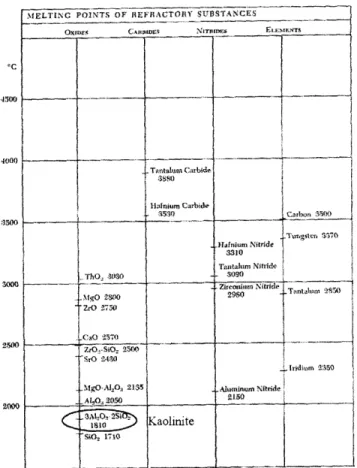
There are five main categories of refractory materials: oxides, carbides, nitrates, borides, and elements. As Figure 18 depicts, the melting points are highest for carbides and lowest for oxides. While it is necessary to find a refractory material that can withstand high temperatures, is a poor conductor, and is a good insulator, it is equally important to make sure that the material also allows the kiln to cool down at the appropriate pace .The last four categories of materials listed above tend to oxidize when exposed to air and have incredibly low conductivity, thus they are rendered useless for kiln purposes (Rhodes 1981). Within oxides, the most useful and available material is clay, and more specifically kaolinite clay which is circled on the chart (Rhodes 1981).
-500O
4EGI)
4000
3W00
Figure 18. Chart comparing refractory materials.
3.7.1 Bricks
Bricks are a conmmon material used to construct a kiln because they are readily available around the world, are easy to maintain and build with, often have refractory properties and are good insulators. For these reasons, the wall will mostly be composed of bricks which will either be available or easy to create. The brick could be combined with an additional material such as alumina to strengthen its refractory properties, either in the brick composition itself or as an additional layer on top.
The brick can be composed of commonly found clay, a reddish brown clay. This is the most available clay in the world, and already has low conductivity and high insulation. However, it can be further improved if a refractory material were combined with the clay before the brick is fired. Kaolin is one of the oxides which is often found in clay. Kaolinite brick is the most commonly used brick for kilns due to its abundant nature and ideal properties.
Another approach to improve the insulation of the wall could be to include an additional material in between layers of bricks. The supplementary material being assessed is an alumina coating.
Aluminum is a metal which has the properties as both a good conductor and heat reflector.12 It is often used in construction when an insulting material is needed. Aluminum itself will not suffice
for this project, because the melting temperature is approximately 933 K (660 "C). However, alumina has a melting temperature of 2320 K (2047 "C), making it a more ideal material, and with the same properties as a good thermal insulator and heat reflector." If this material were
coated in between two layers of bricks for the kiln structure, it may aid in preventing heat loss.
3.7.2 Mortars
Mortar is the substance which attaches bricks together and has a tight molecular structure. It is a refractory cement and the technique in applying the mortar is as important as the mortar itself. The mortar needs to have similar properties as the brick to minimize heat loss. It should be able to withstand any thermal expansion or forces of the brick, so it faces higher requirements. According to The Kiln Book, mortar serves to: "(1) Bond the brickwork into a solid monolithic structure, having greater resistance to mechanical and thermal shocks and stresses; (2) make a gas- or airtight kiln; (3) provide a flat surface between irregular bricks; (4) prevent penetration of slag through the joints" (Olsen 1983).
Refractory mortar is made of refractory clay, so it will have the desired properties; however, it should be monitored so that it doesn't get too dry when being applied. Water should be added so that the mortar has the consistency of thick mud. It should be spread on the bricks with a trowel so that the thickness of the mortar is approximately 1 cm (Itabashi et. al. 2003). At the same time, the amount of mortar used should be minimized because brick is a better insulator and creates a stronger structure. Additionally, since the mortar is made of refractory clay, it may
shrink (Rhodes 1981). Grog can be added to reduce the shrinkage but it best to discuss the mortar with the local hardware store.
3.7.3 Iron
The third material for the kiln is iron for the grate and frame. Iron is the fourth most abundant material on earth and is readily available in Ghana. It will be easy to find in multiple forms including angled, as a rod, and as a sheet. The grate will be composed of iron rods on which the wood or other fuel will be placed and then burned. Iron is ideal for this function because its melting temperature of approximately 1800 K (1527 "C) which will withstand the high
temperature from the flame. Additionally, iron is typically used for supporting purposes and can be used to construct a frame for the kiln due to its strength. A measure of stiffness, the Young's Modulus, is 211 Giga Pascals for iron, which indicates more than sufficient strength.
3.8 Wall Design
'2The Advantages of Aluminum. n.d. 20 Mar. 2007. < http://kyoto-shisaku.com/english/library/arumi/cyosyo.htm>. '3Wikipedia. Aluminum Oxide. 6 May 2007. 19 Apr. 2007. <http://en.wikipedia.org/wiki/Aluminum_oxide>.
The walls of the kiln are critical to minimize heat loss yet still aid in the cooling down process of the filters. The thickness of the wall, as well as the wall's design, needs to be devised taking into account the necessary heating and cooling rates in addition to heat losses.
There are two wall designs being considered for the kiln, one with only bricks and one with bricks and an additional refractory material such as alumina. Both designs consist of 2 layers of bricks, which is standard for Potters for Peace kilns. Both designs were evaluated to see which had the lowest heat loss. The thermal resistance method, described in Section 4.4.2, was used. They were analyzed at steady state to evaluate which would provide a better heat barrier. Surprisingly, it did not result in much of a difference. The calculations, included in Table 4 and determined by the Matlab code provided in Appendix 1, suggest that two layers of brick or two brick layers with an alumina coating will reduce the heat loss by approximately half of just a single brick. It appears that there is not a significant difference with the alumina included and it may be better to find bricks with alumina already mixed in if available. Alumina is merely one type of refractory material, but is not necessary because clay alone is effective at minimizing heat loss. At steady state, it appears that the heat loss through all of the standing walls equals approximately 24.7 Kilowatts for the two bricks with alumina, only 60 Watts less than the wall with just two bricks. These results indicate that the alumina would not significantly reduce heat loss.
Table 4. Compare heat loss through various wall designs.
Wall Design Heat Loss (Kilowatts)
One Brick -46.629
Two Bricks -24.771
Two Bricks with Alumina -24.710
3.9
Recuperation Designs
3.9.1 Recuperation Design Utilizing Power
In addition to maximizing efficiency from a fuel and air flow standpoint, the design of the new kiln intends further efficiency improvements or recuperation designs. For the purposes of this project, the heated air from the chimney will be reused. One common method to recover heat is to use a heat exchanger. It allows for cool air to pass through heated air, thus heating up the cool air during this interaction.
For this project, a design such as Figure 19 would apply, with a pipe being inserted into the chimney. "Cold" air from the atmosphere would pass down through the pipe, getting heated up by the hot air coming up through the chimney. The cold air will not naturally be pushed down the pipe because of the pressure gradient; however, it can be forced down with a strong fan or air blower. The air would be diverted back to the kiln's firebox where the preheated air reenters the kiln, thus quickening the time necessary to heat the air for re-circulation.
Blower
Figure 19. Schematic of recuperation design. The cold air enters the chimney with the aid of the blower and the air is forced down the pipe. The hot air in the chimney which surrounds the pipe heats up the cold air as it flows down the pipe. The air is then diverted back to the firebox where the air reenters the kiln preheated.
This design allows for heated air to be reused, thus improving the fuel and thermal efficiency of the kiln. It would result in a temperature increase of 60 *C for the temperature flowing out of the pipe, reducing fuel consumption by 4 percent.
This kiln design has been proven to work. It was designed by Arthur W. Francis Jr. at Alfred University, as published in the magazine Studio Potter, Vol. 7, No.2. The disadvantage to this recuperation method is the additional power needed to make it work. The fan or air blower is critical in this method, otherwise the cool air will not flow down the pipe.
The additional power requirements for the use of a proposed small fan such as the one in Figure 20 would add the initial cost of setting up electrical capacity and the continued cost from running the fan during kiln operation.
Figure 20. Small air blowers. Two types of air blowers used in kilns. Courtesy of Bailey Pottery'" and Vacuum Guide.15
3.9.2 Recuperation Design Without Power
In a downdraft kiln, the air will move through the chimney in the fashion described above. However, in order to utilize the heat that is being wasted, a couple of recuperation designs have been proposed in order to return some of the heat that has already passed through the kiln and utilize it again in the chamber.
One idea is to have a brick shell surround the kiln. Instead of having the kiln exit flues lead the hot air to the back of the kiln and through the chimney, the air would be directed toward the sides of the kiln, where the fireboxes are. The hot air would then travel upwards in the channel created by the brick shell and the kiln wall. During this process, the hot air would heat the air that is entering the firebox. Hotter air takes less energy to combust, so by heating the air before it is enters the firebox allows more of the energy that is stored in the wood to be transferred to the kiln chamber instead of being used during the combustion process. The reason this design was not pursued was because of the unique chimney shape. It provided too much cross sectional area, and would not gather the air enough to provide a good draft through the kiln.
14Bailey Pottery. n.d. 14 May 2007. <http://www.baileypottery.com/images/blower.jpg>.
Chapter 4: Thermodynamics
4.1
Model Description
The proposed kiln model takes necessary characteristics into account in order to produce the desired filters. These include how the temperature should be distributed throughout the kiln, how heat is transferred in the kiln, how the kiln should be shaped, and how the air flows through the chamber and filters.
4.1.1 Temperature Distribution of Overall Kiln
The kiln needs to have the ability to fire the filters as evenly as possible and gradually increase to the desired temperature over a period of approximately eight hours. Both of these aspects are crucial because of the materials that compose the filters and the properties that the final filters needs to contain.
The filters consist of common clay mixed with sawdust particles or rice husks. As the filter is fired, the combustible burns away, leaving the filter entirely porous. The porosity is needed for the water to flow through the filter. In order to achieve the appropriate porosity, two steps must occur: 1. the correct amount of combustible must be combined with the clay prior to firing, and 2. the combustible must be gradually burned away rather than quickly. The clay itself may be fired at a faster rate than the filter; however, when the combustible is burned, it is necessary for the carbon that results from the reaction to exit the filter without leaving a black or grey vein,
carbon that prevents the water flow.'6 If the temperature in the kiln increases too quickly, the burning sawdust will also burn the filter in that area and may make portions of the filter brittle.
Additionally, the filter needs to be strong enough to hold water on a daily basis for a few years. If it cracks, it is no longer a useful method of water treatment. Since these filters are intended to be sturdy and reliable, the fired filter needs to be evenly baked and withstand the pressure from
the water as well as the force from the bucket or container it is placed in. If the filters are fired too quickly, there is a higher chance of them falling apart or crumbling when in use.
In order to achieve the appropriate state for the filter, the temperature should reach 830°C over a span of approximately eight hours." Additionally, the kiln should cool down gradually for at least eight hours so the filters can set and do not get damaged. These parameters have been proven over the years with kilns used specifically for the Potters for Peace water filters.'"
4.2
Heat Transfer
Heat transfer is an important process that occurs during the firing cycle of the kiln. It is how the latent heat stored in the wood fuel is passed to the filters in order to harden them and make them
"'Ron Rivera, Potters for Peace Coordinator in Nicaragua '7Peter Tamakloe, Owner of Ceramica Tamakloe