Design of a Tree Moving and Planting Device
by
Sean J. Nabar and Salvatore B. Pallante
SUBMITTED TO THE DEPARTMENT OF MECHANICAL ENGINEERING IN PARTIAL FULFILLMENT OF THE REQUIREMENTS FOR THE DEGREE OF
BACHELOR OF SCIENCE AT THE
MASSACHUSETTS INSTITUTE OF TECHNOLOGY
JUNE 2006
02006 Sean J. Nabar and Salvatore B. Pallante. All rights reserved. The authors hereby grants to MIT permission to reproduce
and to distribute publicly paper and electronic copies of this thesis document in whole or in part
in any medium now known or hereafter created. o- 7 Z/
Signature of Authors:
Certified by:
_ I - - v
Department of Mechanical Engineering May 12, 2%
I/
. ,~~~~~~~~~~~~~~:
,01 ;i, I I
David R. Wallace Associate Professor of Mechanical Engineering
l_--_N - _ Thesis Supervisor
Accepted by
ii7~~~O'
John H. Lienhard V Professor of Mechanical Engineering Chairman, Undergraduate Thesis Committee -e - p-? 1 -- jy v J -,0
Abstract
Planting trees that weigh over 200 pounds normally requires three or more able persons. Therefore, a device that allows a single person to easily and efficiently plant such trees possible by one person is highly desirable. During a Product Design class in the Mechanical Engineering Department at the Massachusetts Institute of Technology, a group of 14 students developed a series of four concept models which culminated in a Final Prototype of such a product that can successfully lift, move and plant trees of over 200 pounds. This paper is aimed at documenting this series of designs and analyzing, testing and further developing the Final Prototype built in the course in order to make it marketable. Based on customer feedback, testing results, and user interaction, revisions to the next prototype of this device are proposed. Testing with trees of 170 and 370 lbs determined that the current outrigger stabilizing mechanism needs modification. The current outriggers, which are stored inside the frame, sustained maximum loads of 29 lbs for the 170 lbs tree, and 46 lbs for the 370 lbs tree. A sketch model built to simulate the outrigger mechanism suggests that the outriggers should be attached outside the base frame of the device rather than stored inside. The revised device is also to include two stacked pipe clamps for securing the vertical member members of the outriggers. The upper and lower frames are to be reduced in width from 42 to 36 inches, making the device more compact while still accommodating tree root balls of up to 3 feet in diameter. Nylon insulation of the current winch wire is necessary to prevent damage to tree trunks while operating the device. These design revisions will improve the performance of the device Final Prototype and are believed to make the revised device commercially viable on the product market.
Table of Contents
1.0 Introduction ... 4
2.0 M arket Analysis ... ... 7
2.1 Market Attributes for Customers ... 8
2.2 Other Competitive Products ... 9
3.0 Product Development Process ... 13
3.1 Evolution of the Product Design ... 13
3.1.la Idea Sketch ... 13
3.1.lb Design Changes Implemented After Idea Sketch ... 14
3.1.2a Hydraulic Jack Model ... 15
3.1.2b Design Changes Implemented After Hydraulic Jack Model ... 17
3.1.3a Winch Model ... 18
3.1.3b Design Changes Implemented After Winch Model ... 21
3.1.4 Final Prototype ... ... ... 2525... 4.0 Customer Feedback ... ... ... 31... 31
5.0 Experiments and Testing of Final Prototype ... 33
5.1.1 Ability to Lift and Maneuver Trees ... 33
5.1.2 Load Capacities ... 35
5.2 Outrigger Testing ... 37
5.2.1 Necessity of Outriggers ... ... 37
5.2.2 Load measurements on Outriggers ... 38
5.2.3 Effect of Longer Outriggers ... ... ... 38
5.3 Effect of Tree Weight ... ... ... ... 42
5.4 Effect of Elevation ... ... ... ... .... 5.5 Different Types of Terrain ... ... ... ...45
5.6 User Interaction ... ... ... 488... 6.0 Revised Device ... ... ... 50
6.1 Winch Design ... ... ... 50
6.2 Wheel Design ... ... ... 50
6.3 Outrigger Sketch Model ... ... 51
6.4 Frame Design ... ... ... 55
6.5 Winch Wire Design ... ... 58...58
6.6 Revised Device Summary ... ... ... 60
7.0
Conclusion
...
... ...
61
8.0 Future W ork ... ... ... 65
1.0 Introduction
Planting trees of over 200 pounds normally requires a group of three or more able persons, and heavier trees require even more man power. The process includes digging a large hole of at least twice the diameter of the root ball, lifting the tree, moving it to its desired final location, and carefully lowering the tree to prevent damage or injury [1]. A single-person operable device that can be used to ease this process is a beneficial tool for landscapers and other tree planters. In addition, making a device operable by only one person can drive down labor costs and increase productivity and efficiency. The City Roots program of Boston is an organization that focuses on moving and planting trees in urban areas. This non-profit organization has been the motivation for this project. Currently, the program relies on both youths and elderly volunteers to plant their trees. The difficulties associated with moving and planting trees by such volunteers made the need for a device that could assist in the process.
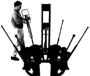
During the course 2.009, a product development class in the Mechanical Engineering Department at the Massachusetts Institute of Technology, a prototype for a device that can be used to lift, move and plant trees was developed and built by a group of 14 students. The device that was built was tested and able to successfully lift, maneuver, and plant trees over 200 pounds. The final prototype was developed after a series of modifications and iterations to previous design ideas. The final Alpha Prototype that was presented is shown below in Figure 1.
Figure 1: The tree device being demonstrated during the final presentation. It is holding
a tree of over 200 pounds and being operated by one person
The folding capabilities of the device were important to its portability, making transportation in the bed of a standard pick-up truck possible while leaving room for other objects as well. The aluminum frame provided a lightweight body and strongly reinforced structure capable of handling heavy trees and impacts from obstacles. With careful design and building of the device, the team of students was able to create a working product from start to finish that was directed towards tackling the difficulties associated with tree planting.
The goal of this thesis project is to take the alpha prototype presented in the class and analyze it based on its testing, user and customer interaction, and ability to enter the market as a commercially viable product. In addition, various design improvements are proposed based on testing of the prototype and user feedback. The tree moving device was met with enthusiasm from design engineers in the Boston area as well as tree planting organizations, and thus encouraged the exploration of further marketing and effectiveness capabilities. The markets that will be analyzed are the current landscaping
and tree planting market for home gardeners and small-scale landscapers. Current contact with the City Roots program has provided the majority of the customer feedback.
The thesis also chronicles the evolution of the design all the way from a simple paper sketch to the working prototype that was presented at the final review. Four milestones reached during the class helped to guide the design along a path that had many choices and ideas. With each design concept, however, significant changes were made to improve both aesthetics and the functionality of the design.
Testing was performed as a part of this thesis on the device subsequent to the final review. The tests and results are documented to gain an understanding of the device's abilities to repeatedly lift and plant trees as well as get a better range of tree sizes that it is able to lift. From the testing results, it was made clear that there were noticeable areas for improvements even after the final prototype of the class was presented.
By combining the market guided need for such a product with user interaction of the device and testing results, suggestions for a fifth design concept are made for the improvement of the device. With these results and design ideas, the device is one step closer to being finalized as a product.
2.0 Market Analysis
A product that can be used to lift, move and plant trees would be primarily useful to landscaping organizations. The City Roots program of Boston is a non-profit organization in the area that plants trees at various times of the year between the spring and fall. In addition, this type of device could be used by small-scale landscapers, home gardeners, and other organizations like City Roots. This type of product could provide a tremendous advantage to these types of organizations.
There are many different types of trees that are planted each year. Amongst the types of trees that are most commonly planted are coniferous and deciduous. These trees, shown in Figure 2, differ in size and shape and season of bloom. These trees, which are often planted by landscapers, homeowners, and non-profit organizations, can be difficult to plant because of their occasional large size and weight. In addition, it "requires a group of people to maneuver these heavy trees around a planting location" [2]. A device that can be used for both of these types of trees and operated by a single person would be an ideal tree planting equipment addition.
Figure 2: Coniferous trees (left) and deciduous trees (right) at a nursery before planting.
The root balls generally weigh between 150 and 300 lbs, an ideal range for the tree
moving device.
2.1 Market Attributes for Customers
The key product attributes for a device that can lift, move and plant trees vary with respect to customer. The most important attributes which are taken into consideration for the different types of potential customers are: device portability; ability to maneuver, lift, and plant large trees; single person operation; and competitive sale price and affordability. These attributes of importance are based on feedback from users affiliated with City Roots.
Even though each of the key product-attributes is important for a successful device, some of the characteristics may be relatively more critical for a specific customer group. For landscaping companies, it would be advantageous to own this type of device because landscapers work at remote locations and often plant in addition to transporting trees. Single person operation would drive down labor costs for landscaping companies.
For home gardeners who plants trees on their own properties, this device would also be very useful and efficient. Many of these people are homeowners and recreational gardeners who do not have multiple workers at their disposal so it would be very important for such a device to be operable by a single person and for the device to be low cost. A competitive price and the ability to plant large trees by a single person are the key attributes for home gardeners who would be interested in purchasing such a device. Non-profit organizations that plant trees would look for a competitive price, portability to reach remote location sites, and the ability to quickly and efficiently plant trees into holes. For an equipment rental company, which would be renting such a device to customers such as home gardeners, it would be very important that the product is easily transportable from the company to the location site. A low price would be a factor in the decision of a rental company to purchase such a device, but renting out of the device could quickly make back the initial purchase cost.
Table 1, below, summarizes the different types of customer and the key product attributes that would be likely to affect their decision to buy this product.
Table 1: Types of potential customers and the major product attributes affecting decision
to buy the device.
Customer Key Product Attributes
Landscaper Device Portability, Ability to Plant Large Trees Home Gardener Single Person Operation, Competitive Sale Price
Non-profit Organization Device Portability, Ability to Plant Large Trees, Competitive Sale Price Equipment Rental Company Device Portability
2.2 Other Competitive Products
There are two other types of related products that are currently being marketed, which can be used to lift, move and plant large trees. The first of these types of products
is what is commonly known as a tree dolly [3]. The other type of product, produced by a company called Tree Toad and is known as the Tree Toad Tree Transporter [4].
A tree dolly is a product that can lift and move trees. Tree dollies come in many different sizes, and can accommodate many different sized and shaped root balls and trees. These dollies can be used to lift and move trees to a location that is near the hole in which a tree is going to be planted; however, the dollies do not offer any assistance to a user as he or she is lowered the tree into the hole. These devices can be easily transported to location sites, and "one person can usually handle most trees alone."
Tree dollies typically cost between $350 and $550, and their price varies depending on the size of the tree which can be accommodated. Figure 3 below shows a picture of one type of tree dolly that can accommodate a root ball of up to 40". The device measures 62" in height, 34" in width and has a 20" cradle. [5]
Figure 3: A competitive product, known as a tree dolly, which can be used to lift and move trees.
The product advantages and disadvantages for such a device are summarized in table 2 below.
Table 2: Product advantages and disadvantages of a competitive product, a tree dolly.
Product Advantages Single Person Operation Competitive Price: $350 -$550 Device Portability
Ability to Lift, Move Large Trees
Product Disadvantages Lack of Ability to Plant/Lower Trees
The main product disadvantage that comes from using a tree dolly is that it does not assist the user with the process of planting the large tree. For a very large tree, the process of planting the tree can require as much as 4 persons to do and it is often the timeliest part of the entire planting process. A key design improvement over the tree dolly is that this device will significantly aid the user in planting trees.
The TreeToad Tree Transplanter, on the other hand, can dig out previously planted trees in addition to moving and planting new trees. Tree Toads come in different sizes, and can accommodate different sized rootballs and trees. These devices are difficult to transport to a location site because of their large size. Tree toads typically cost between $850 and $2520 [6]. Figure 4 shown below is a 32" 6-spade model of a TreeToad Tree Transplanter.
1
The product advantages and the product disadvantages for such a device are summarized in Table 3 below.
Table 3: The key product advantages and disadvantages of a competitive product, a Tree
Toad Tree Transplanter.
Product Advantages Single Person Operation
Ability to Plant/Lower Trees
Ability to Lift and Move Large Trees Ability to Dig Holes
Product Disadvantages Lack of Device Portability
High Price: $850 -$2450
The main product disadvantage of the Tree Toad Tree Transplanter is that the device is large and consequently can be difficult to transport to a location site. In addition, the TreeToad is relatively expensive when compared to the tree dollies that were previously mentioned.
3.0 Product Development Process
The following section documents the evolution of the tree moving device throughout the semester-long course. With a design team of 14 mechanical engineering seniors, each step was carefully analyzed and criticized before being carried out. The team consisted of some students heavily focused on engineering product design with others concentrating in management and economics. The ideas and input from such a group of student engineers rendered a product that was both highly technical, yet commercially viable and market oriented.
3.1 Evolution of the Product Design
The device evolved from an increasing pool of ideas as the semester progressed, but there were four major milestones during the term that ultimately shaped the final design and helped guide its progression. These design concepts began with an initial brainstorming session to pinpoint a particular project on which to work. Once the tree moving goal was selected, drawn sketches as well as simple sketch models were constructed to gain an idea of how the product would work. From these models, the next design concept was to incorporate a more robust design that actually worked. This concept would also give an idea of how the product interfaced with users who would regularly operate it. By learning from each individual design concept and working towards fixing each concern, a complete design was produced and presented to a wide range of reviewers and design professionals.
3.1. la Idea Sketch
Originally, concepts in the course for a semester long product development period were brainstormed. As a problem that was visible and addressable, the transporting and
planting of heavy trees was chosen. To create a device that could solve these problems effectively and efficiently, initial design ideas were sketched out. The first design idea that was considered involved a frame, strapping system, and two wheels and could be operated by a single person. The design concept is pictured below in Figure 5.
Figure 5: Initial design concept involving a frame, strapping system, and two wheels.
This design concept could be implemented using a sturdy frame made of aluminum or steel. The strapping system could be manufactured using chains or nylon material which would need to be load rated to a capacity that is capable of carrying the load of a tree.
3.1. lb Design Changes Implemented After Idea Sketch
The main drawback to using such a design concept was the heavy load that was being carried on the shoulders of the user. Since the intention of the design concept is to minimize the difficulty of moving and planting a large tree, this design, which requires the user to carry a portion of the load from the tree on their shoulders, was abandoned. The main design change that was implemented after this design concept was abandoned
was to use a mechanical device to significantly reduce the load being carried on any part of the user's body. In addition, the original design concept involved the operator facing away from the tree and pulling it along behind him or her. This design only then addressed the issue of transporting the tree. A device that would make planting and positioning of a tree easier would require the operator to be facing the tree and location in which to plant. From the original design concept, these two design requirements were noted and would be implemented on prototypes in the future.
3.1.2a Hydraulic Jack Model
The second design concept that was considered involved a triangular frame, hydraulic jack, lifting boom, strapping system, and three wheels. As a mockup prototype, the second design was intended to provide additional insight basic design concepts that could be fine tuned for future reviews. The second design is pictured below in Figure 6.
Figure 6: Hydraulic jack mechanism that was used as a basis for the Hydraulic Jack
Model. A jack like the one pictured here was attached to an aluminum frame to complete the design. [7]
This design concept could be implemented using a frame made of aluminum and the strapping system could be manufactured using chains or nylon material which would once again be load rated to a capacity that was capable of carrying the load of a tree. The hydraulic jack would also be load rated to a capacity that was capable of carrying the load of a tree. Figure 7 shows a mockup of the Hydraulic Jack Model.
Figure 7: Mockup of the Hydraulic Jack Model, which utilized a hydraulic jack and
aluminum frame as it is being used to lift and move a tree. Here, a student is operating the prototype with a test-size tree.
The prototype was successfully able to lift and move trees. Planting trees, however, was difficult because the device was designed to lift the root balls of trees from the ground and then could only lower them back to the same elevation. In actuality, the holes in which root balls must be planted are at least three feet in depth. Thus, a larger range of heights to which the device could plant and lift from was necessary. In addition, the tires were not sturdy enough for all landscaping terrain maneuverability and the
handles were too not robust enough to manage the extreme forces and torques involved with moving trees of hundreds of pounds.
3.1.2b Design Changes implemented after Hydraulic Jack Model
One of the main drawbacks of the Hydraulic Jack Model is that the device was large and would be difficult to maneuver and transport around a location site. For stability reasons, it was necessary to have a large base when using the Hydraulic Jack Model because the base would prevent the device from tipping over while a tree is being planted or on inclines and angles commonly associated with landscaping locations. Still, a large base would require extra material, driving up cost and weight, and also reduce the portability and storage capabilities of the device considerably. A primary goal to reach for the next design concept was then to decrease the size of the base while maintaining stability.
In addition, it was found from testing that the use of a hydraulic jack proved to have some difficulties with regards to user interaction. Through user trials, it seemed apparent that many users did not find the function of a hydraulic jack to be intuitive. The lowering of the root ball with the jack involved quickly releasing amounts of its air pressure, and made lowering of trees a spasmodic process. The hydraulic jack was very far from the location of the root ball, which made it an effective lever operator, but the tradeoff was that the boom experienced an extreme bending moment and visibly deflected. User comments focused on the slow lifting time associated with the hydraulic jack, which took nearly thirty seconds to raise a tree just two feet. Also, users found the hydraulic jack as a possible barrier to eventually making the device portable because it was placed at the logical folding pivot point.
The main design changes that were implemented after this design mockup were to use a winch mechanism rather than a hydraulic jack and to change the design of the frame. A winch would be much easier, quicker, and more intuitive to operate for raising and lowering trees. It would also be possible to lower trees into holes rather than simply back to the height they were lifted from. Changes to the frame would involve making the base smaller and adding a more user-friendly handle. Additionally, a new mechanism would have to be introduced for actual testing of tree lowering. When the device would be placed in front of a hole, and the tree lowered, the device would likely tend to flip over into the hole, posing a serious injury risk. The next prototype would also include some type of outrigger mechanism for balancing the device while planting.
3.1.3a Winch Model
The third design idea that was considered involved a modified frame, strapping system, a winch, a boom, the previously proposed outriggers, and once again, three wheels. This design took into account the results from the earlier review and included changes based on the user feedback. The new modified design concept model is pictured below in Figure 8.
Figure 8: Solid model of the Winch Model which involves a frame, a winch, a boom,
outriggers, and three wheels. The strapping belts can be readily attached to the boom.
This design concept also employed a frame made of aluminum box extrusions. The boom as well was made of aluminum box extrusion material and the outriggers were made of long steel beams. The winch used was a worm gear winch that was load rated at 1000 pounds, well above the necessary capacity [8]. The strapping system was made using nylon material. The aluminum box extrusions, worm gear winch, outriggers and nylon materials were all load rated to a capacity that was capable of carrying a tree that was at least 300 lbs. Figure 9 shows a mockup of the Winch Model. Using the mockup, one operator was successfully and easily able to lift, move and plant a tree.
Figure 9: Mockup of the Winch Model which involved aluminum frame, wheels, a
boom, a winch and a strapping system.
The purpose of the designing removable outriggers was to reduce the size of the main frame. These outriggers would span across the hole and sustain a normal force from the ground balancing out the moment of flipping forward caused by the tree. They could be inserted only before loading and unloading the tree and could be removed when the device was empty or when the tree was already in transportation position, eliminating many of the difficulties of maneuvering and transporting around the obstacles of the location site. Figure 10 shows the outriggers being successfully used to position and lower the tree into a hole.
Figure 10: Mockup of the Winch Model being used to plant a tree. The outriggers, which
are painted orange, are successfully being used to prevent the device from tipping while the tree is being lowered.
3.1.3b Design Changes implemented after the Winch Model
The use of a winch mechanism attached to the boom was found to be an effective mode of controlled lifting and lowering of the tree. Through testing of different types of winches, it was found that worm gear winches had the best safety and reliability characteristics. The use of a worm gear winch with an integrated braking system was necessary to prevent the winch from unloading itself while holding heavy trees in the upright position.
The use of removable outriggers proved to be an effective way to decrease the size of frame and still maintain stability while raising and lowering the tree. From testing, it was found that detachable outriggers were problematic, as users often found it difficult and time consuming to remove and insert the outriggers each time the tree was raised and lowered. In addition, even though the outriggers were removable, they would still have to be transported along with the device in order to eventually load or unload a tree, and so multiple trips would be required if only one person tried to operate the
device. For these reasons it was necessary to integrate the outriggers into the frame of the device.
The use of a boom which was made of one single member was found to be problematic for two main reasons. It had a tendency to interfere with the tree and possibly damage the tree by cutting into its trunk while lifted. Also, its connection to the frame was under heavy load as the tree was being lifted and maneuvered. In particular, as the tree was being moved around uneven terrain, there were large torsion forces that were found to cause the pivot points to bend and rotate. In some cases, these torsion forces were not counterbalanced, and consequently caused instability in the entire device.
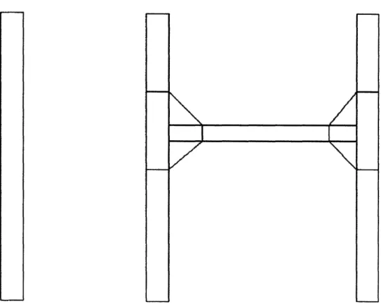
By changing the design to involve a two member boom, rather than a single member boom, the design was able to address these two issues. A double membered boom would allow the device to lift a tree without having the boom interfere with the trunk. In addition, an it would divide the load amongst two connecting members rather than just one member and it would allowed the device to better counterbalance torsion forces and instabilities that would be caused by these forces. The structural difference between the single and double member booms are highlighted in figure 11 below.
Figure 11: (Left) A drawing of the single member boom. (Right) Sketch of double
member boom that is connected with a cross member bar and reinforced with aluminum gussets.
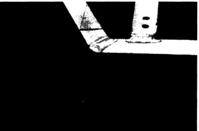
The frame consisted of aluminum box extrusions that were welded together. The design of this frame caused high stress at some junctions on the device. In particular, during testing it was found that some of these points were unable to withstand the stresses and the welds were broken. The corners of the device where the box extrusions were welded were the first points to fail when the device was first tested. Figure 12 shows one of the junction points of the device where the failure occurred.
Figure 12: Aluminum box extrusion joint after failure. The load from the tree was too
great, and the joint was not adequately reinforced, causing an unzipping like failure.
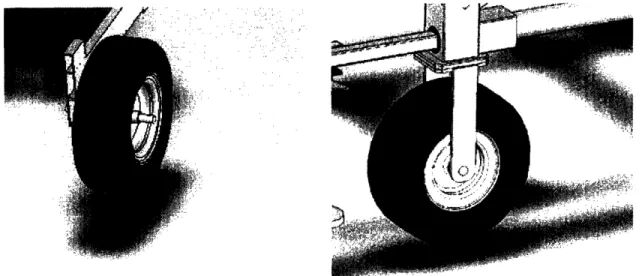
To avoid having any sharp corners or other points that are under high stress, it was decided that the aluminum extrusions should be bent rather than welded. By bending the aluminum, the sharp corners were changed to round corners and the peak stress in any one point was lowered by doing so. The aluminum box extrusions would be replaced by aluminum metal tube. Bending the corners would also require that the majority of the base from is made from one long cylindrical pipe that could be bent in multiple locations. Cantilevered wheels were used for the front wheels of the device. As the device was loaded, the shaft that was holding the wheel had a tendency to rotate. To avoid this problem, the wheels used during the next iteration were changed such that they were no longer cantilevered. Figure 13 shows the two different types of wheels.
Figure 13: Two different types of wheel designs. On the left, is a model of a design that
used wheels that were cantilevered. On the right, is a model of a design that avoided the use of a cantilevered wheel.
Other design comments from users included confusion about how to use the nylon straps to suspend the root ball, and that the design needed additional portability capabilities. The final changes, then, would be to change the nylon suspension straps to
metal chains, making the strapping system significantly more intuitive. In addition the handle and winch portion would be foldable to make the device shorter when folded and easier to store in a vehicle or storage area.
3.1.4 Final Alpha Prototype
While implementing the design since the Winch Model, different grades of aluminum were considered for use. Based on the popularity of aluminum 6061 grade, this type of aluminum was, at first, the type that was to be used to build the frame. The aluminum 6061 was put into the bending machine and as it was being bent to an angle of 90 degrees, it fractured. The aluminum 6061, which was a circular extrusion of 2" diameter and 0.125" wall thickness, was unable to withstand the stresses that were caused during the bending process.
After finding that aluminum 6061 was unable to withstand bending to large angles, aluminum 6063 was instead used to build the frame of design concept 4. Aluminum 6063, which was also a circular extrusion of 2" diameter and 0.125" wall thickness, was found to be able to be bent to angles of 90 degrees without fracture.
The fourth and final design idea involved a frame which was further rounded and modified, a strapping system, a winch, a double member boom, outriggers that were integrated into the design, and three wheels. This design accounted for design changes that were introduced after the Winch Model was tested. The new modified design concept is pictured below in Figure 14.
Figure 14: Solid Model of the Final Alpha Prototype involving a frame which was
further modified, a winch, a double member boom from which straps are to be attached,
outriggers, and three wheels. The outriggers (discussed later in this section) are
retractable into the frame.
Components of the aluminum frame were manufactured by bending aluminum circular extrusions. The pieces of aluminum circular extrusion were then joined by
welding the aluminum members of the frame together. The frame was further modified in a way such that it could fold. By making the frame foldable, the overall height of the device while folded could be significantly reduced. This reduced height is important in allowing the device to be easily transported and stored. From customer interaction, it was found that many landscapers and non-profit organizations that plant trees were very concerned about being able to bring a product such as this to a plant site via a pickup truck. Figure 15 shows how this folding mechanism is designed and how it functions.
Figure 15: Two configurations of the Final Prototype. (Left) The device is in its
operable mode, prepared to lift or move tree. (Right) The device is in its folded state and
ready to be stored or easily transported.
The strapping system used was made of steel chains and nylon straps. The steel chains, hanging down from the double member boom, were connected to a nylon strap which had a seatbelt mechanism that was used to join the ends of the nylon strap together. The nylon strap could then be readily cinched around the root ball of a tree and hold it for transportation. The purpose of using steel chains and nylon straps in the Final Alpha Prototype, as opposed to using just nylon straps which were used in the Winch Model, was to make it more clear to the user how the use the strapping mechanism. The hanging steel chains would not tangle with each other, and having the nylon straps at the
bottom made it more intuitive where the tree was to be gripped from. In addition, the use of steel chains offered a more robust looking-strapping system. Figure 16 shows the strapping system that was used.
Figure 16: The strapping system of design four, complete with cable chains for
suspension and belts for cinching of the root ball. The belts can be readily loosened or
tightened with an airplane seatbelt clip.
The double member boom was made using aluminum box extrusion just like the rest of the frame and the previous single member boom. The aluminum box extrusions were joints designed to provide a large contact area for welding. To provide additional support, gusset plates were added at the locations where the comprising members of the boom were joined. Figure 17 shows the double member boom that was used along with the strapping system attached.
Figure 17: Overhead view of the device used for design concept 5. This view shows the
double member boom and winch wiring arrangement used.
The outriggers were integrated into the design with two major components. One component of the outrigger is a steel square beam that slides horizontally and smoothly in and out of the aluminum main base frame. Another component of the outrigger is a vertical bar that slides through a locking mechanism on the horizontal beam and moves up and down. On the bottom of the vertical outrigger component, a bearing piece with a flat under surface was added to act as a foot. The feet on the ends of the vertical bars would push into and hold on almost any terrain, preventing the device from tipping forward while loading or unloading a tree. The new outriggers could be deployed and retracted quickly as well as transported along with the device while inactive. Figure 18, below, shows the outrigger mechanism design.
i*s!i·: :·-'" '.:3C'ais":j··, :·, . *·?·* ,!;a:iil ':'··*'·;· :· ie ;Fi·i. :-'*..". ·tii· I.·; :4c:- : : ;r ':':''" :-· ·X"'I ;t%; .. xr 1··----' ... .i· ·;;1:·.·· 4 . · · · ·:` ' - -;^"··
Figure 18: The outrigger mechanism of the device is shown here. The horizontal bar on
top can be slid out to a desired length to facilitate force balancing while loading and unloading the tree. The vertical bar, or outrigger foot, can then be lowered to touch the ground.
These final modifications and designs after a series of reviews concluded the semester long course and design of the tree moving device. The following section will include a detailed testing pattern and validation of the current concept.
4.0 Customer Feedback
From speaking with potential customers, in particular the City Roots representatives, about this final presentation prototype, it was clear that there existed areas for improvement. Feedback forms with viewer questions and concerns were made available that included improvement suggestions about the device. Among the improvements suggested, a decrease in size and price, a more intuitive and ergonomic winch design, and a better working outrigger mechanism were the most frequently mentioned.
Many of the potential customers of this product seemed particularly concerned with the current size of this product. It was generally found that the current size of the Final Alpha Prototype was too large. A large device is disadvantageous for any rental company because it has little storage and stacking capabilities in inventory warehouses, and is difficult to transport for customers who rent. A large device is also disadvantageous for landscapers, or any non-profit corporation, because of its problem with transportation to a location site where planting will occur.
During the presentation of the Final Alpha Prototype, the price of the manufactured device was presented at $1,200. This price was an estimate determined by the group based on an expected material cost for large scale production, labor time, and industry markup. Some reviewers found the price to be too high for the product's capabilities. In particular, the City Roots program expressed that "a price of under $1,000 would be more reasonable and affordable for non-profit tree planting organizations." [9]
The winch design on the prototype for the Final Alpha Prototype is hand operated. One recommendation from a groundskeeper was that an improvement to this design would be a battery operated winch. Since a battery operated winch would be more costly, and a battery would need to be charged regularly, this concept will not be implemented.
The outrigger design on the Final Prototype was not sufficiently robust for some potential customers. One possible way to improve on the apparent strength of the outriggers is to change the size of the material that is used. By using a larger box extrusion, the design of the outriggers can be made to appear more robust.
5.0 Experiments and Testing Results
After the final review, a device made to lift, move, and plant trees by a single person had been developed and prototyped. However, detailed testing or user analysis was performed on the alpha prototype to assess its reliability, safety, and general usability. In this section, a series of tests are performed and documented to generate ideas about improvements to the original design of the tree planting device. Tests conducted on two cherry trees of different sizes and weights were used to determine the parameters that would be best fit to vary. In addition, the continual use of the device for testing purposes would be very conducive to fostering ideas about the user interface. Repeated use of the device provided to be the best method of harvesting design improvements and optimization.
5.1.1 Ability to Lift and Maneuver Trees
The lifting and maneuvering capabilities of the device were tested by using trees of different weights. The two major tree subjects of the testing experiments are shown below in Figure 19. The trees, having different size and weight characteristics gave an adequate range of commonly planted trees.
Figure 19: Shown are the two trees used for testing and analysis for the tree moving and
planting device. On the left is the smaller cherry tree of 170 lbs. The right one, also a cherry tree, is over twice as heavy, at 370 lbs.
First, a tree weighing 170 lbs was lifted and maneuvered around a parking lot as well as a grassy area. It was found that it is possible to lift and maneuver this tree with relative ease. The process of turning the winch handle was not considerably difficult or very labor intensive. The winching of the tree still required a bit of strength, but "nothing too difficult for average-strength home gardening females" [10].
Following the feasibility test on the smaller of the trees, a tree that weighed 370 lbs was lifted and maneuvered in similar fashion. During the loading process, it was found that it is considerably more difficult to crank the winch handle and lift the tree up to its maneuvering location. While it was possible to turn the winch handle and raise this tree off the ground, the process of turning the winch handle was much more labor intensive, requiring the operator to put in the entire body's effort, and took more time.
Operators performing tests commented that "the 370 lbs tree was significantly harder to lift" [11]. Once the tree was lifted to its upright location, it was found that the tree was maneuverable with the current wheel design. The 370 lbs tree was noticeably harder to move around just because of its weight on the castor wheel. During turns, the castor wheel occasionally became difficult to pivot, in effect, increasing the turning radius of the entire device.
5.1.2 Load Capacities
When testing the load capacity of the current design, the structure of the design was discovered to be capable of lifting and holding a tree that weighed 370 lbs. In addition, it was found that the structure was capable of holding 400 lbs of free weights during an earlier load capacity test. Figure 20 shows the structure holding the 400 lbs of weight in comparison to the 370 lbs tree used in the tests. With these heavy weights secured in the straps, the device was still operable. However, it was apparent that there were high stresses in the joints of the frame and that the device would not be able to withstand much higher loads. The device was not tested to failure because only one prototype existed. Failure testing would be very useful in further development of this device and should be performed if additional prototypes are available in the future.
Figure 20: (Left) The device in a load testing phase, raising 400 lbs of free weight.
(Right) The device being tested and maneuvered with a 370 lbs tree in the transport position.
These two photos show the load carrying capabilities of the device.
While the structure was capable of holding up to 400 lbs of weight, it was found that the winch mechanism became difficult to use when trying to lift a 370 lbs tree. In addition, it was more difficult to maneuver the device with a heavy tree. From the testing, it was found that, by having a winch mechanism that has a lower load capacity than the load capacity of the structure, users could avoid machine failure. For instance, by having a winch that is not capable of lifting a load that would cause failure, the user of the device will not be able to use the machine to lift a load that will cause any part to dangerously fail or malfunction.
For this reason, the final design implementation should include a winch with a lower load capacity than its structural load capacity. By doing so, the winch will impose a limit based on safety as well as maneuverability of the device, precluding any injury
risk or possible problem that could occur after a heavy tree has already been lifted and positioned.
5.2 Outrigger Testing
Two different types of tests were performed involving the outrigger design mechanisms implemented in the Final Alpha Prototype. The first of the tests was in order to determine whether or not there was a need for the outriggers for balancing the device while loading and unloading. The second test was to determine the load on an outrigger as a function of the weight of the tree, the extension the winch cable, and extension length of the outrigger.
5.2.1 Necessity of the Outriggers
In order to determine whether the outriggers were necessary, different trees were lifted from different positions while the vertical bars of the outriggers were not extended to the ground. First, a 170 lbs tree was lifted from flat terrain. This tree was able to be lifted to its upright position on the device without the outriggers being extended onto the ground. Next, this 170 lbs tree was lifted from a lower elevation than the wheels. It was found that when this tree was lifted from a hole, or lower elevation similar in depth to that of a hole, that it was necessary to deploy the outriggers. Without the use of outriggers, the device is not stable, posing a serious injury risk to the operator. After lifting this 170 lbs tree, a 370 lbs tree was lifted from flat terrain. This tree could not be lifted off the ground without the outriggers being extended. Thus, lifting of a tree much heavier than 170 lbs would require working outriggers regardless of the terrain from which it was being lifted.
Based on these test results, it was found to be necessary to include outriggers on this type of design concept since there can be several scenarios and locations where the machine will not be operable without them. The outriggers, in addition to facilitating easier lifting of trees, would increase the safety of operation by balancing the device while lifting, and preventing accidental tipping.
5.2.2 Load Measurements on Outriggers
Different tests were done to determine the loading on the outriggers under different scenarios. First, two tests were performed to determine the load on the outriggers as a function of the length that the outriggers were extended. Next, a test was done to determine the load on the outriggers when they were extended onto flat terrain from the device versus when the device was positioned in front of a hole, or a sharp drop in elevation, and the outriggers were extended into the hole. Finally, tests were performed to determine the load on the outriggers as a function of the weight of the tree that was being tested.
5.2.3 Effect of Longer Outriggers
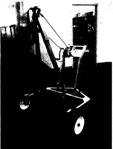
The first test that was done was to determine the load on the outriggers as a function of the length of the outriggers that were extended. It was found that when the outriggers were extended further, the load on the outriggers was less. Figure 21, below, shows the device loaded with a tree and the outriggers fully extended.
Figure 21: The device is loaded with a 170 lbs tree and the outriggers are fully extended
to a length of 32". The outrigger length can be varied by pulling out the horizontal member from the frame. This test also included a trial with the outrigger at 16".
The load testing was performed using a simple bathroom scale positioned under one of the outriggers. The other outrigger maintained contact with the ground due to its vertical variability and presumably sustained an identical load due to symmetry. To test the load on the outriggers with respect to the length of the winch cable, the tree was loaded into its upright, maneuvering position and then the outrigger foot was placed onto the middle of the scale. The tree was then lowered one half turn at a time and the resulting loads were recorded. The length of the winch cable that been reeled out was known and provided precise lengths for each load data point.
While testing the 170 lbs tree, it was found that when the outriggers were extended by 16 inches and 32 inches that the maximum load on the outriggers were 27 lbs and 10 lbs respectively. Figure 22 shows the load on the outriggers as a function of
the length of the winch cable extension, when the 16" long outriggers and 32" long outriggers were used to lower the 170 lbs tree onto flat terrain.
"U a, 20 20 -.
15-0
C 10-05
o-* 16" Long Outnggers onl _ 211 1 an Nitnnr - QC. LI J ULIII~~ * S U--. 0 5 10 15 20Length of Winch Cable Extension (in)
Figure 22: Load on the outriggers as a function of the length of winch cable that was
extended. The maximum load on the outriggers was 27 lbs and 10 lbs when the outriggers were extended to 16 inches and 32 inches respectively.
In the figure, it is seen that the load in the outrigger is greater while extended 16" but stays relatively constant while extended 32". When the outriggers are extended further, there is an advantage in moment balance and less force is exerted on the outriggers while maintaining stability and safety. The sudden drop in load on the 16" extended outriggers marks the length of the cable when the root ball of the tree began to make contact with the ground. The drop in load when the root ball touched the ground for the 32" extended outriggers test is also noticeable, but much less drastic. The four pounds displayed on the scale at length extension of zero inches and the final extension shows the weight of the foot of the outrigger plus the zero offset in the bathroom scale.
While testing the 370 lbs tree, it was found that when the outriggers were extended by 16 inches and 32 inches that the maximum load on the outriggers were 46
lbs and 29 lbs respectively. Again, the maximum load on the fully extended outrigger is lower than that of shorter extension. Figure 23 shows the load on the outriggers as a function of the length of the winch cable extension when the 16" long outriggers and 32" long outriggers were used to lower the 370 lbs tree onto flat terrain.
Figure 23: Load on the outriggers as a function of the length of winch cable that was
extended. The maximum load on the outriggers was 46 lbs and 29 lbs when the outriggers
were extended to 16 inches and 32 inches respectively.
It can be seen that both outrigger lengths now have a relatively constant upward slope, which is different than the test involving the lighter tree. The 32" outriggers are now taking increasing weight due to the heaviness of the tree as opposed to the constant load they were bearing in the previous test. As expected, the 16" outriggers bear more weight than the 32" extension because they are closer to the center of mass of the system. Again, the drastic drop in load shows the winch cable length when the root ball hits the ground and the load in each outrigger is lessened dramatically. In this experiment, at the maximum outrigger load point, each outrigger was sustaining between 30 lbs and 46 lbs each, making the total outrigger load between 60 lbs and 92 lbs. These values are a
* 16" Long Outnggers =An , ,m ' 9" I nnn N ltrinnrm 45 -2 40-en 35 -g 30
-.
25 -O 20 -o 15- 10-5I 0-0 5 10 15 20Length of Winch Cable Extension (in)
. ~ ~ ~ ~ ~ .. . . .. . .. . ...
--.. ..
·...
, ,.__m
+ , +...
. . --- - - -- -. ...
.--- -
-. .. 'i .. . . .,- .... I .
tou-significant percentage of the total tree, and prove that while lifting trees of such large weights, outriggers are entirely necessary to ensure safety.
5.3 Effect of Tree Weight
Additional testing was performed to determine the effect that the weight of the tree has on the load sustained by the outriggers. To test the effect of the weight of the tree, two different trees were lowered onto flat terrain while the outriggers were extended to a distance of 16 inches. It was found that the maximum load on the outriggers when lowering the 170 lbs tree was 27 lbs and the maximum load on the outriggers when lowering the 370 lbs tree was 46 lbs. Figure 24 shows the load on the outriggers as a function of the length of winch cable extension, for the lowering of the 170 lbs tree and the 370 lbs tree. _ 17n Ikh- Tr.l a. 7IIV IU Ih Tr; an ,,, .q70 IhQ Tro uu
-'
50 -40 -0 co · 30-0
O 20 -0 , 10 - o-0 5 10 15 20Length of Winch Cable Extension (in)
.1**
1_*1
Figure 24: Load on the outriggers as a function of the length of winch cable that was
extended. The maximum load on the outriggers was 27 lbs when the 170 lbs tree was
lowered and 46 lbs when the 370 lbs tree was lowered.
The loads increase at almost an identical rate until the winch cable reaches around one foot extension. Then, as expected, the heavier tree requires a larger load weight placed on the outriggers. The 170 lbs tree touches the ground at a shorter extension than
the 370 lbs tree because of the location in which the trees were cinched. The test verifies the maximum loads on the outriggers at extension of 16 inches as 27 lbs for the 170 lbs tree and 46 lbs for the 370 lbs tree.
5.4 Effect of Elevation
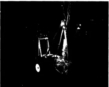
In order to determine the effects of elevation and ground conditions on the outriggers while lifting trees, two tests were performed. In the first test, the 170 lbs tree was lowered onto flat ground at the same elevation at the wheels of the device. Next, the same tree was lowered off a curb step roughly a foot and a half high to the flat ground, in order to simulate the difference between lowering onto the ground and lowering it into a hole. In both cases, the outriggers were extended to a length of 16 inches. Figure 25 shows the test in which the tree was lowered off a curb.
Figure 25: The device is loaded and prepared for testing from a curb step. As seen in a
previous experiment, the tree device would tip without engaging the outriggers. Here, the outriggers are still to be extended to the ground before taking data.
While lowering the tree into a depressed elevation, it was found that there was a much greater load on the outriggers. While lowering the tree onto flat ground, the maximum load on the outriggers was 27 lbs; and when lowering the tree onto a lower elevation, the maximum load was 65 lbs. Figure 26 shows the load on the outriggers as a function of the length of the winch cable extension when the 170 lbs was lowered onto flat and depressed elevations.
* Level Elevation ofn - tC FI\A+;Mn-Cnr i- OU - 70 -60 -U) 40 . 40 o 30 -0 ,a 20 -cO, 3j I -0 0 5 10 15 20
Length of Winch Cable Extension (in)
Figure 26: Load on the outriggers as a function of the length of winch cable that was
extended. The maximum load on the outriggers was 27 lbs when the outriggers were used on flat terrain and 65 lbs when the outriggers were used on depressed terrain.
These data suggest that the use of outriggers is much more critical when a tree is being lowered into a hole. The load on each outrigger is consistently at least twice as great on outriggers while lowering into a hole as while lowering the tree to level ground. From these results, it is apparent that outriggers must always be engaged while lowering or raising a tree from a depressed elevation in order to avoid flipping of the device.
libII.~.l~ O U l.II~V(;I lJI I
. .*vl coocU LIUVV IVI
. . . + *
U
.·*
. ..*a * * * * -~.I
.. - - ...
5.5 Different Types of Terrain
To get an idea about the maneuverability of the device on various terrains that could be involved in the tree moving and planting process, the tree moving device was loaded and driven over different types of grounds. The types of terrains upon which the device was tested include level concrete ground, inclined concrete ground, grass, dirt, and snow. First, the device was tested on level concrete ground and it was found that maneuverability on concrete ground was quick and efficient with the current wheel design. With this wheel configuration and these types of wheels, the design was capable of moving and turning easily and quickly on concrete ground. Figure 27 shows the device as it maneuvered on concrete ground.
Figure 27: The device is loaded and prepared for testing from a curb step. As seen in a
previous experiment, the tree device would tip without engaging the outriggers. Here, the outriggers are still to be extended to the ground before taking data.
In addition, the device was maneuvered over standard obstacles associated with concrete ground such as speed bumps and dips. The speed bumps could also simulate mounds of dirt commonly found around planting areas. The device was very easily
maneuvered while traveling straight and making slight turns. Sharp turns were also facilitated by the castor wheel that made them very efficient. The best way to climb over a speed bump was with the wheels slightly angled so that the device was not driving directly over it. This reduced the force necessary to be applied while going over obstacles.
The device was then maneuvered over grass and dirt to determine the feasibility of this wheel design and configuration for this type of terrain. Movement of the device through this type of terrain was slightly more difficult than movement on concrete ground; however, it was still very manageable to push, pull and turn the device while on grass and dirt ground. The ground was slights damp and wet due to recent rain and snowfall that added moisture to the terrain. For this reason, the wheels sunk into the ground a bit more than usual while pushing. Figure 28 shows the device as it is maneuvered on grass and dirt.
Figure 28: The device is loaded and prepared for testing from a curb step. As seen in a
previous experiment, the tree device would tip without engaging the outriggers. Here, the outriggers are still to be extended to the ground before taking data.
The grass and dirt seen in the picture was fairly soft making the maneuverability less than optimal. However, many dirt and grass planting locations have much harder ground surfaces. In these locations, the device would be even easier to maneuver. Through mud, the device could be difficult to maneuver, especially if the tires sink into the ground significantly. However, this test was performed on relatively uncooperative terrain and the device was still safely maneuverable.
The ability to maneuver the device through snow was then tested. There were approximately 2 to 3 inches of snow on the ground in the area where the device was used and, as expected, it was found that it is more difficult to move the device through snow than just through dirt terrain. It was still manageable to push, pull, and turn the device on the snow. Figure 29 shows the device as it is maneuvered on snow.
Figure 29: The device is loaded and prepared for testing from a curb step. As seen in a
previous experiment, the tree device would tip without engaging the outriggers. Here, the outriggers are still to be extended to the ground before taking data.
For soft snow mounds, shown in the picture on the right, the tires could plow through the snow with relative ease.
One of the concerns that arose when testing movement over different types of terrain was that it was difficult to push the device over curbs that were greater than 3 inches. It was found that it was significantly easier to pull the device over curbs.
One way to allow greater maneuverability over curbs is to increase the size of the wheels. Based on feedback from potential customers, however, increasing the size of the wheels is not recommended, since it will increase the size of the overall device in both the folded and unfolded positions.
5.6 User Interaction
User interaction with the device was monitored to determine potential design changes that would be beneficial. To gain insight into the use of the device by people unfamiliar with it, two people were chosen to operate it without any instruction or prior information except for the overall goal of the device. This would provide information about whether the tree moving device possesses an intuitive design that can easily be figured out. It would also give general user observations and suggestions for
improvement.
Based on feedback from users who interacted with the device, suggestions were made about the maneuverability, portability, and the comfort of operation associated with it. It was noted that the ability to fold and unfold the device was somewhat difficult. The folding challenges, however, were due to misalignment between the upper and lower frames in the prototype. This problem could be rectified with more careful construction, as the two frames were designed to mate properly. Also, the straps dragged on the floor as the device was being transported. Finally, it was noted that when the outside
temperature was approximately 30°F, the aluminum began to feel very cold and became uncomfortable to handle.
6.0 Revised Device
Based on testing and feedback of the manufactured Final Prototype, additional ways to improve the design were considered. The improvements and design ideas for a next generation of the device are incorporated in this section, as a suggested way to design the next iteration of this product.
6.1 Winch Design
The current winch design was implemented using a hand winch with brake enclosed gear box. The use of this winch design posed two main problems: First, the winch handle needed to be extended by approximately two feet which resulted in an awkward looking design. This extension of the winch handle needed to be built in order to allow the winch to be used without interference with the frame. Second, under high loads, the winch handle on this type of winch became difficult to turn and often made the process of lifting a heavy tree very labor intensive and slow.
The possibility of using an electric motor winch instead of a manual winch was considered; however, it was determined that an electric motor winch was not desirable. While the use of an electric motor will eliminate the need for a handle extension and will make the motor less labor intensive, it was found that a motor winch would still not be feasible since it is not cost effective and would require either a battery or other electricity source.
6.2 Wheel Design
The Final Alpha Prototype design has three wheels in a tripod orientation. The front two wheels are non-castor wheels and the back wheel is a castor wheel. It was found during testing that this type of wheel configuration is stable and maneuverable.
With this type of wheel configuration, the device was found to be unlikely to tip over and it was easy to make sharp turns over different terrains, thus changes to the wheel configuration are not recommended.
6.3 Outrigger Sketch Model
The difficulties associated with the operation of the outriggers, prompted the construction of a sketch model to develop a new method of designing and operating the outriggers. The problem with the outriggers from the outset was their storage and transportation. With the Winch Model, it was seen that the outriggers would be entirely detachable and would have to be carried along with the tree device separately while not being used for loading or unloading. In the Final Prototype, the outriggers were part of the main frame of the device and could telescope out for deployment. In this model, however, there were problems with the outriggers' horizontal members getting jammed inside of the frame. This could lead to considerable problems in operation and even dangerous safety hazards.
The sketch model focused on an idea of having the outriggers still attached to the frame of the device, but not being stored inside of the frame. Instead, the outrigger would lie just on the lower frame and slide out smoothly from above. The sketch model
for the concept was constructed with wood, but using the same vertical outrigger components. In Figure 30, below, the sketch model is shown.
Figure 30: Sketch model of the next design concept outrigger. This wooden model
displays how the outrigger will be operated and deployed. The horizontal member can slide in and out smoothly over the frame member. The housing, at the end of the frame maintains the outrigger angle and keeps it attached to the device.
This model eliminates the need for running the horizontal member of the outrigger through the base of the frame. The horizontal part of the outrigger will set on top of the device base frame and smoothly slide out for loading and unloading. After the tree is securely in position, the outrigger can be slid back in towards the wheel and facilitate easier transportation.
The block seen above the sliding outrigger resembles the handle bar of the frame. The handle will operate the same as before, but rest on top of the outrigger. In effect, there will be no lost space in storage by moving the outriggers on top of the bottom frame. The handle will now rest horizontally in position, presenting a better engineered look and when folded, it will appear that there are three members - the handle, the outrigger, and the base frame - neatly stacked upon each other.
One problem encountered while operating the outriggers was the inability to fix the vertical members in place. This was mainly due to the type and quality of the pipe clamps. As seen back in Figure 18, the outrigger has a clamp on the bottom of the horizontal member to hold the foot in place. These pipe clamps, however, could only hold the vertical member without slipping in one direction. The vertical member clearly needs to be held from sliding up while loading and unloading in order to bear the load of the tree. The original design took this into consideration and held the outrigger from slipping up. However, the clamp did not secure the vertical member from slipping down as a result of gravity and its weight. The safest configuration would be to have a clamp that locks the vertical member from moving in either direction.
The sketch model was thus fitted with a pipe clamp arrangement that would hold the vertical member locked in one place throughout the duration of operation. The clamp arrangement can be seen in Figure 31, below.