HAL Id: inria-00336858
https://hal.inria.fr/inria-00336858
Submitted on 5 Nov 2008
HAL is a multi-disciplinary open access
archive for the deposit and dissemination of
sci-entific research documents, whether they are
pub-lished or not. The documents may come from
teaching and research institutions in France or
abroad, or from public or private research centers.
L’archive ouverte pluridisciplinaire HAL, est
destinée au dépôt et à la diffusion de documents
scientifiques de niveau recherche, publiés ou non,
émanant des établissements d’enseignement et de
recherche français ou étrangers, des laboratoires
publics ou privés.
An IEEE 802.16 WiMAX Module for the NS-3
Simulator
Jahanzeb Farooq, Thierry Turletti
To cite this version:
Jahanzeb Farooq, Thierry Turletti. An IEEE 802.16 WiMAX Module for the NS-3 Simulator.
[Tech-nical Report] 2008, pp.11. �inria-00336858�
***** In Submission, November 3rd 2008 *****
An IEEE 802.16 WiMAX Module for the NS-3 Simulator
Jahanzeb Farooq
INRIA, Planete Project 2004 Route Des Lucioles 06902 Sophia Antipolis, France
[email protected]
Thierry Turletti
INRIA, Planete Project 2004 Route Des Lucioles 06902 Sophia Antipolis, France
[email protected]
ABSTRACT
ns-3 is a recently released next generation simulator intended as a replacement of the popular ns-2. It enables a highly rich set of features and is expected to become the first choice of the scientific community soon. ns-3 is in its evolution phase and work at different fronts is still ongoing. With the recent emergence of broadband wireless networks, sim-ulation support for such networks, especially IEEE 802.16 WiMAX, is becoming a necessity. In this paper, we pro-pose and discuss in detail the design and implementation of an IEEE 802.16 WiMAX module for ns-3, with the Point-to-Multipoint (PMP) mode and the WirelessMAN-OFDM PHY layer. Our module implements fundamental functions of the convergence sublayer (CS) and the MAC common-part sublayer (CPS), including QoS scheduling services, band-width request/grant mechanism, and a simple uplink sched-uler. The aim is to provide a standard-compliant and well-designed implementation of the standard.
Categories and Subject Descriptors
H.4 [Simulation and Modeling]: Model development— modeling methodologies
Keywords
IEEE 802.16, WiMAX, network simulation, ns-3
1.
INTRODUCTION
With the increasing demand of high data rates and larger wireless coverage, broadband wireless access networks have rapidly emerged over the last few years. The IEEE 802.16 standard [1], widely known as WiMAX (Worldwide Interop-erability for Microwave Access), defines the MAC (Medium Access Control) and PHY (Physical) layers specifications for the broadband wireless access networks. WiMAX offers an alternative to wired networks, such as coaxial systems us-ing cable modems, fiber optics and DSL (Digital Subscriber Line). It offers high speed data access to large geograph-ical areas, covering distance up to 50 Km and supporting
data rates up to 100 Mbps, depending on the distance from the base station and the underlying PHY layer. With this range and data rates WiMAX standard is capable of deliv-ering backhaul connections for enterprise campuses, WiFi hotspots and cellular networks.
The MAC layer of WiMAX supports Point-to-Multipoint (PMP) and Mesh topologies. The wireless medium access is based on either Time Division Multiple Access (TDMA) or Frequency Division Multiple Access (FDMA), with FDD (Frequency Division Duplex) and TDD (Time Division Du-plex) as duplexing techniques. Multiple PHY layer speci-fications are supported for LOS (Line-of-Sight) and NLOS (Non-Line-of-Sight) operational environments in 10-66 GHz and 2-11 GHz frequency bands, respectively. Later on the IEEE 802.16e amendment [3] added mobility support to WiMAX networks.
The network simulator ns-2 [6] is one of the most widely used simulators in the academic and industrial community since the last decade. The newly released ns-3 [7], primarily intended as a replacement of ns-2, is a completely new sim-ulator rewritten from the scratch. It introduces major en-hancements over its predecessor and has all the capabilities of becoming the leading network simulator in near future. A few among the many salient features of ns-3 are a com-pletely re-written software core with fully documented API, high emphasis on conformance to real networks, easier soft-ware integration, support for simulating virtual networks, support for testbeds, attribute system for configuring sim-ulator parameters, automatic memory management, and a configurable tracing system, etc [14]. The first release of ns-3 (version ns-ns-3.1) was made in June 2008 with support for a number of modules including CSMA, Point-to-Point, 802.11 WiFi, TCP, UDP and IPv4. The development on a number of modules is still in progress.
Currently there are a number of WiMAX modules available for ns-2, all based on PMP topology with TDD duplexing. The module proposed by Networks and Distributed Systems Laboratory (NDSL) [11], one of the first WiMAX modules available, supports, among other features, scheduling ser-vices and bandwidth management. However the module is highly simplified as it ignores several implementation details and thus is not compliant to the standard. The module pro-posed by National Institute of Standards and Technology (NIST) [4] provides a number of features including OFDM PHY layer and fragmentation and de-fragmentation.
How-ever it lacks the implementation of QoS scheduling services. Later a collaborative effort between WiMAX Forum, Rens-selaer Polytechnic Institute (RPI) and Washington Univer-sity St. Louis (WUSTL) adds support for QoS scheduling services, ARQ mechanism and OFDMA PHY layer to this module. The updated module is now officially adopted by the WiMAX Forum [8] and is available for download for members. Note that a plug-in proposed by Telecom Bre-tagne [9] also extends the NIST module with QoS scheduling services feature. Finally, a recent module proposed by Com-puter Networks Laboratory (CNL) [10], basically based on DOCSIS module [2], supports scheduling services and band-width management, however it lacks implementation of a WiMAX compliant PHY layer. Unfortunately, the highly non-modular design of the NDSL and CNL modules makes them less attractive for the developers who aim to extend them with new features and plug-ins.
Our module is based on the IEEE 802.16-2004 standard and ns-3 version 3.2. The code1 is available under the GNU
General Public License. It implements the PMP topology with TDD mode and aims to provide detailed and stan-dard compliant implementation of the stanstan-dard, supporting important features including QoS scheduling services, band-width management, uplink request/grant scheduling and the OFDM PHY layer. The module is built completely in C++ with 36 classes and approximately 17000 lines of code. Be-side the fact that it is the first WiMAX module for the ns-3 simulator, the module distinguishes itself from above modules in the respect that high attention has been put to make the design fully object-oriented, facilitating modular-ity, reusabilmodular-ity, scalability and maintenance of software. Uni-fied Modeling Language (UML) has been used for the design and analysis phase. We believe this work a significant contri-bution to the scientific community as it allows simulations of WiMAX networks with a more close-to-real implementation of the standard, and with the add-on flexibility of plugging-in new modules plugging-in its various components. Furthermore, with the added benefits of ns-3, the module enables features such as flexible and detailed tracing functionality, simulation of real networks and TCP/IP-stack, emulation, and defining new simulation scenarios using the Helper API.
The remainder of the paper is organized as follows. Section 2 presents a brief overview of the IEEE 802.16 standard. Sec-tion 3 presents detailed descripSec-tion of the proposed module including its software design, the MAC and PHY layers and the detailed operation of each component. Future develop-ment and enhancedevelop-ments are discussed in Section 4. Finally Section 5 concludes our work.
2.
OVERVIEW OF IEEE 802.16 STANDARD
This section presents a brief overview of the IEEE 802.16 standard. For a more comprehensive overview please refer to [13] or [20].
The IEEE 802.16 standard defines MAC (Medium Access Control) and PHY (Physical) layers specifications for a Broad-band Wireless Access (BWA) network. The physical medium is divided into frames of fixed length. Each frame is further
1The code is available at the following URL:
http://code.nsnam.org/iamine/ns-3-wimax/.
divided into DL (downlink) and UL (uplink) subframes for the downlink and uplink traffic. The structure of frame de-pends on the underlying PHY layer. The standard defines multiple PHY layers for different operational environments. For the 10-66 GHz band the WirelessMAN-SC PHY, based on single carrier modulation, is defined. For frequencies be-low 11 GHz, where propagation without a direct line of sight (LOS) must be accommodated, three alternatives are pro-vided: WirelessMAN-SCa using single carrier modulation, WirelessMAN-OFDM using Orthogonal Frequency Division Multiplexing, and WirelessMAN-OFDMA using Orthogo-nal Frequency Division Multiple Access. The standard sup-ports two duplexing techniques: FDD, where DL and UL subframes take place at the same time but on different fre-quencies, and TDD, where DL and UL subframes take place at different times and usually share the same frequency. The MAC layer is divided into three sublayers. The CS (Convergence Sublayer), MAC CPS (Common-Part Sublayer) and the Security Sublayer. The CS Sublayer is responsible of receiving PDUs (Protocol Data Units) from the higher layer, classifying these PDUs to appropriate connections, process-ing these PDUs and deliverprocess-ing them to the appropriate MAC SAP (Service Access Point). The MAC CPS (Common Part Sublayer) provides the fundamental MAC functionalities in-cluding connection establishment and management, gener-ation of MAC management messages, SS initializgener-ation and registration, ranging, bandwidth management, service flow management and scheduling services. Two modes for shar-ing the wireless medium are defined: in the PMP mode Sub-scriber Stations (SS) communicate to each other through a Base Station (BS), and in the Mesh mode the stations are organized in an ad-hoc fashion and communicate to each other directly.
The MAC protocol is connection-oriented which means all the communication takes place in terms of connections. There are two types of connections: management connections for transmitting control messages and transport connections for data transmission. The registration phase includes an ini-tial ranging phase in which special management messages RNG-REQ and RNG-RSP are exchanged between SS and BS. The BS on receiving RNG-REQ examines parameters such as power level and if acceptable allocates a set of man-agement connections to the SS. These connections are then used to transmit and receive control messages.
The MAC defines a set of control messages, called MAC management messages. The most important of these mes-sages are DL-MAP, UL-MAP, DCD and UCD. At the be-ginning of each frame the BS broadcasts the DL-MAP and UL-MAP messages that define access to the DL and UL sub-frames of the current frame. These messages contain a set of information elements (IE), each notifying an SS of the DL or UL grant allocated to it. These are followed by DCD and UCD messages which contain general information about the channel and a set of burst profiles, each burst profile defin-ing a set of parameters that must be used to send or receive data in a given DL or UL grant.
All the data traffic is carried on transport connections. There is a one-to-one relationship between a transport connection and a service flow. A service flow defines a unidirectional
flow of data traffic and binds it with a set of QoS parame-ters. A wide range of QoS parameters are supported by the standard. Special MAC management messages DSA-REQ and DSA-RSP are exchanged between SS and BS to create a service flow.
The standard defines four scheduling services (or QoS classes), named UGS (Unsolicited Grant Service), rtPS (Real-Time Polling Service), nrtPS (Non-Real-Time Polling Service) and BE (Best Effort). UGS is designed for real-time applications with fixed size packets. UGS flows are allocated unsolicited grants on periodic basis. rtPS is designed for real-time appli-cations that generate variable size packets on periodic basis. Unlike UGS, a rtPS flow is polled by the BS on periodic basis allowing it to send bandwidth requests. The request is then serviced based on the available bandwidth. Compared to rtPS, nrtPS is designed for more delay-tolerant applica-tions. A nrtPS flow is ensured a minimum bandwidth by polling it on regular basis even in congestions conditions. Finally, BE (Best Effort) is designed for best effort traffic such as HTTP and Email and does not guarantee a min-imum bandwidth. The 802.16e amendment introduces an additional class named ertPS (Extended Real-Time Polling Service) that combines features of UGS and rtPS by allowing unsolicited grants for variable packet size applications. Bandwidth is requested by sending a bandwidth request packet. It is sent either in a special transmission opportunity allocated in UL subframe or in an uplink grant allocated to the SS. BS then responds with a grant allocated in subse-quent frames. The uplink scheduler at the BS decides which SSs to allocate bandwidth in the next frame based on re-quests. Note that bandwidth is requested on per connection basis but allocated on per SS basis. This is then the respon-sibility of the SS scheduler to decide which connection will transmit in a given grant. Similarly the BS scheduler selects packets that will be transmitted in DL subframe. Note that standard does not define any scheduling algorithm for these schedulers and leaves this up to the manufacturers to decide.
3.
THE PROPOSED IEEE 802.16 MODULE
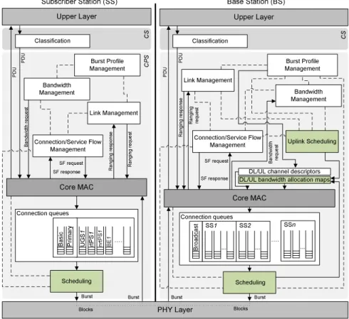
The proposed module is mainly composed of three layers: the CS (Convergence Sublayer), the MAC CPS (Common-Part Sublayer) and the PHY layer. At the PHY layer two
different PHY implementations are supported. Figure 1
presents a block diagram of the module, illustrating some of its key components and their interaction. Subsequent sections provide detailed description of the three layers and the key components.
3.1
Software Design
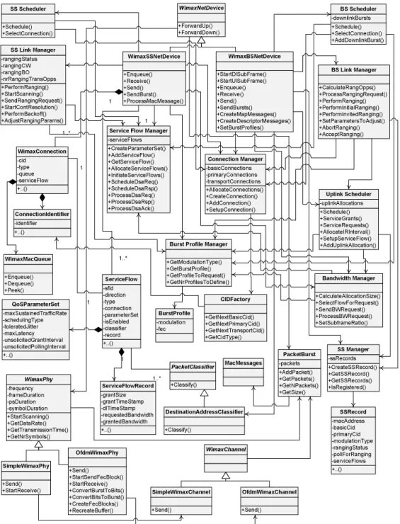
The design of the module thoroughly follows object-oriented analysis and design methodology in order to benefit from the classic characteristics of object-oriented software con-struction including modularity, polymorphism, encapsula-tion and inheritance, and to conform to fully object-oriented design of ns-3. UML (Unified Modeling Language) has been adopted especially for the Design and Analysis phases of the SDLC (System Development Life Cycle). More specifi-cally, software construction techniques presented in [18] have been widely followed. The class diagram of the module is presented in Figure 2. Note that the diagram only shows important data members and functions and details such as
multiplicity have been omitted due to limited space. As seen in the figure, the module is composed of several C++ classes each representing a core component of the system and tak-ing care of a particular functionality. Responsibilities have been carefully delegated to different classes/components to ensure high cohesion and low coupling. High attention has been put to design an API that ensures reusability, scalabil-ity as well as maintainabilscalabil-ity of the software. The modular design facilitates extension of the software in future. Addi-tions of new components and plug-ins, such as new PHY or scheduler implementations, can easily be made.
3.2
The Convergence Sublayer
The 802.16 MAC layer is divided in to two sublayers. The Convergence Sublayer and the core MAC layer called MAC Common-Part Sublayer. CS is further sub-divided into two types: the Packet CS and the ATM CS. Our module im-plements the Packet CS, designed to work with the packet-based protocols at higher layers. The CS is responsible of receiving packet from the higher layer and from peer sta-tions, classifying packets to appropriate connections (or ser-vice flows) and processing packets. It keeps a mapping of transport connections to service flows. This enables the MAC CPS identifying the QoS parameters associated to a transport connection and ensuring the QoS requirements. The CS currently employs a simple classifier based on des-tination MAC address. Support for other standard compli-ant classifiers is aimed in future (see Section 4). Note that the optional feature of PHS (Payload Header Suppression), which allows suppressing the repetitive portion of the pay-load headers, is not implemented by the module.
3.3
The MAC Sublayer
The MAC CPS is the main sublayer of the IEEE 802.16 MAC and performs the fundamental functions of the MAC. The module implements the PMP mode. In PMP mode BS is responsible of managing communication among multiple SSs. The key functionalities of the MAC CPS include fram-ing and addressfram-ing, generation of MAC management mes-sages, SS initialization and registration, service flow man-agement, bandwidth management and scheduling services. Class WimaxNetDevice in Figure 2 represents the MAC layer of a WiMAX network device. This class extends the Net-Device class of the ns-3 API that provides abstraction of a network device. WimaxNetDevice is further extended by BaseStationNetDevice and SubscriberStationNetDevice classes, defining MAC layers of BS and SS, respectively. Besides these main classes, the key functions of MAC are distributed to several other classes to achieve software characteristics discussed in Section 3.1. As seen from Figure 2, some of the key classes that implement the MAC functions include Link Manager (for both SS and BS), Uplink Scheduler, Scheduler (for both SS and BS), Connection Manager, Service Flow Manager, Burst Profile Manager and Bandwidth Manager.
3.3.1
Framing and Management Messages
The MAC is partitioned into frames of fixed duration. The module implements a frame as a fixed duration of time, i.e., frame boundaries are defined with respect to time. Each frame is further subdivided into DL and UL subframes. The module implements the TDD mode where DL and UL oper-ate on same frequency but are separoper-ated in time. A number
PHY Layer Base Station (BS) Subscriber Station (SS) Link Management Connection/Service Flow Management Bandwidth Management Classification Upper Layer Uplink Scheduling Scheduling Link Management Connection/Service Flow Management Burst Profile Management Burst Profile Management Bandwidth Management Classification Scheduling Core MAC Core MAC Ba sic Pr im ary UG S 1 rtP S 1 nr tP S 1 B E 1.... Connection queues SS1 .... ... ... SS2 Br oa dc as t ... SSn Connection queues Upper Layer
DL/UL bandwidth allocation mapsDL/UL channel descriptors
R an gi ng re qu es t B an dw id th re qu es t R an gi ng re sp on se SF request Ban dw id th re qu es t SF response SF request SF response R an gi ng re qu es t R an gi ng re sp on se P D U P D U P D U P D U
Burst Burst Burst Burst C S C P S C S Blocks Blocks
Figure 1: Block diagram of the proposed WiMAX module.
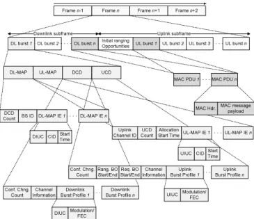
of DL and UL bursts are then allocated in DL and UL sub-frames, respectively. Since the standard allows sending and receiving bursts of packets in a given DL or UL burst, the unit of transmission at the MAC layer is a packet burst. The module implements a special Packet Burst data structure for this purpose (see Figure 2). A packet burst is essen-tially a list of packets. As seen in Figure 1, the BS downlink and uplink schedulers (represented by classes BS Scheduler and Uplink Scheduler in Figure 2) are responsible of gen-erating DL and UL subframes, respectively. In the case of DL, the subframe is simulated by transmitting consecutive bursts (instances of PacketBurst class). In case of UL, the subframe is divided, with respect to time, into a number of slots. The bursts transmitted by the SSs in these slots are then aligned to slot boundaries. The frame is divided into integer number of symbols and PS (Physical Slots) which helps in managing bandwidth more effectively. The number of symbols per frame depends on the underlying implemen-tation of the PHY layer (see Section 3.4). The size of a DL or UL burst is specified in units of symbols. Figure 3 shows the format of implemented MAC frame and the key management messages DL-MAP, UL-MAP, DCD and UCD. MAC management messages play fundamental role in IEEE 802.16 MAC. A number of management messages are de-fined. These messages only carry control information and are transmitted on management connections (including pre-defined broadcast and multicast connections). The most im-portant of these messages are DL-MAP, UL-MAP and DCD and UCD. DL-MAP and UL-MAP are called DL and UL
bandwidth allocation maps and define access to the down-link and updown-link, respectively. DCD and UCD are called channel descriptors and contain information about the chan-nel and how data shall be transmitted/received on it. Next subsection describes these messages in further detail. In addition to these messages, the standard defines separate sets of management messages to carry specific tasks such as ranging, registration, service flow management, burst profile management and so on. The module currently implements the following management messages: DL-MAP, UL-MAP, DCD, UCD, RNG-REQ, RNG-RSP, DSA-REQ, DSA-RSP and DSA-ACK. The module implements these messages, as well as the regular packets and the 802.16 MAC head-ers, Generic MAC Header, Bandwidth Request Header, and Grant Management Subheader, utilizing ns-3’s Packet/Header API, that, among other features, allows bit-by-bit serializa-tion and de-serializaserializa-tion of the packet bytes with the help of the underlying byte buffer. This serialized representation of the data in the packet is done to match real network packets, in order to facilitate features such as emulation.
DL-MAP/UL-MAP and DCD/UCD Messages Figure 3 shows the format of the DL-MAP, UL-MAP, DCD and UCD messages. DL-MAP and UL-MAP messages define access to the DL and UL subframes of the MAC frame. The Allocation Start Time field of UL-MAP indicates the start-ing time of the UL subframe, relative to the beginnstart-ing of the DL subframe. As seen in figure, DL-MAP and UL-MAP contain a set of special data structures, called IE (Informa-tion Element). Each IE notifies an SS (or set of SSs) of an
+Schedule() +SelectConnection() +AddDownlinkBurst() -downlinkBurstsBS Scheduler +Schedule() +SelectConnection() SS Scheduler +CalculateAllocationSize() +SelectFlowForRequest() +SendBWRequest() +ProcessBWRequest() +SetSubframeRatio() Bandwidth Manager +Schedule() +ServiceGrants() +ServiceRequests() +AllocateIRInterval() +SetupServiceFlow() +AddUplinkAllocation() -uplinkAllocationsUplink Scheduler +CreateParameterSet() +AddServiceFlow() +GetServiceFlow() +AllocateServiceFlows() +InitiateServiceFlows() +ScheduleDsaReq() +ScheduleDsaRsp() +ProcessDsaReq() +ProcessDsaRsp() +ProcessDsaAck() -serviceFlowsService Flow Manager
+CreateSSRecord() +GetSSRecord() +GetSSRecords() +IsRegistered() -ssRecordsSS Manager +Send() +StartReceive() SimpleWimaxPhy +GetModulationType() +GetBurstProfile() +GetProfileToRequest() +GetNrProfilesToDefine()
Burst Profile Manager
+AllocateConnections() +CreateConnection() +AddConnection() +SetupConnection() -basicConnections -primaryConnections -transportConnections Connection Manager +PerformRanging() +StartScanning() +SendRangingRequest() +StartContResolution() +PerformBackoff() +AdjustRangingParams() -rangingStatus -rangingCW -rangingBO -nrRangingTransOpps SS Link Manager +CalculateRangOpps() +ProcessRangingRequest() +PerformRanging() +PerformInitialRanging() +PerformInvitedRanging() +SetParametersToAdjust() +AbortRanging() +AcceptRanging() BS Link Manager +Send() +StartSendFecBlock() +StartReceive() +ConvertBurstToBits() +ConvertBitsToBurst() +CreateFecBlocks() +RecreateBuffer() OfdmWimaxPhy +Send() OfdmWimaxChannel +StartScanning() +GetDataRate() +GetTransmissionTime() +GetNrSymbols() -frequency -frameDuration -psDuration -symbolDuration WimaxPhy WimaxChannel +Send() SimpleWimaxChannel +Enqueue() +Dequeue() +Peek() WimaxMacQueue +AddPacket() +GetPackets() +GetNPackets() +GetSize() -packetsPacketBurst +Classify() PacketClassifier +Classify() DestinationAddressClassifier +..() -sfid -direction -type -connection -parameterSet -isEnabled -classifier -record ServiceFlow +..() -cid -type -queue -serviceFlow WimaxConnection +..() -maxSustainedTrafficRate -schedulingType -toleratedJitter -maxLatency -unsolicitedGrantInterval -unsolicitedPollingInterval QoSParameterSet +..() -macAddress -basicCid -primaryCid -modulationType -rangingStatus -pollForRanging -serviceFlows SSRecord +..() -grantSize -grantTimeStamp -dlTimeStamp -requestedBandwidth -grantedBandwidth ServiceFlowRecord MacMessages +..() -identifierConnectionIdentifier +GetNextBasicCid() +GetNextPrimaryCid() +GetNextTransportCid() +GetCidType() CIDFactory +ForwardUp() +ForwardDown() WimaxNetDevice +Enqueue() +Receive() +Send() +SendBurst() +ProcessMacMessage() WimaxSSNetDevice +StartDlSubFrame() +StartUlSubFrame() +Enqueue() +Receive() +Send() +SendBursts() +CreateMapMessages() +CreateDescriptorMessages() +SetBurstProfiles() WimaxBSNetDevice 1 1 1 1..* 1..* 1 1..* 1 -modulation -fec BurstProfile
Figure 2: Class diagram of the proposed WiMAX module.
upcoming DL or UL burst (or grant).
The detailed contents of DL-MAP and UL-MAP IE are as follows. Each DL-MAP IE includes, among others, a CID field identifying an SS (or a set of SSs in case of multicast or broadcast) that will be receiving the corresponding DL burst, and a DIUC (Downlink Interval Usage Code) indicat-ing a burst profile to be used to receive the burst. A burst profile defines a set of PHY parameters that the SS must use to send or receive packets. DL and UL burst profiles are defined in DCD and UCD, respectively. DL-MAP IE also includes a Start Time field that allows SSs to go into sleep
mode and wake up when start time is elapsed. This field is currently not utilized as the module does not implement the power saving feature. Similarly, each UL-MAP IE notifies of an upcoming UL grant. Besides the CID of the SS that is allocated the grant, it includes a Start Time field that marks the beginning of the grant, a duration field indicating duration of the grant, and a UIUC (Uplink Interval Usage Code) that maps to a UL burst profile in the UCD message. DCD and UCD messages include information about the chan-nel as well as a set of burst profiles. The Burst Profile Manager component (see Figures 1 and 2) is responsible
Frame n-1 Initial ranging Opportunities Frame n+1 Frame n Framen+2 UL burst 1
DL burst 1 DL burst 2 DL burst n
Downlink subframe Uplink subframe
DL-MAP UL-MAP DCD UCD
DCD Count BS ID Conf. Chng. Count Channel Information Downlink Burst Profile n Uplink
Burst Profile 1 Burst Profile Uplink n
Start
Time UL-MAP IE n
Start Time
UIUC Modulation/FEC DIUC Modulation/FEC
Conf. Chng. Count Rang. BO Start/End Downlink Burst Profile 1 Uplink Channel ID UIUC CID CID DIUC Channel Information DL-MAP IE 1 MAC PDU n MAC PDU 1 MAC message payload MAC Hdr. UCD Count
UL burst 2 UL burst 3 UL burst n
DL-MAP IE n UL-MAP IE 1 Allocation Start Time Req. BO Start/End
Figure 3: Format of the MAC frame and key man-agements messages.
of defining burst profiles and creating these messages. UCD message contains important parameters including the back-off limits for the contention ranging and bandwidth request processes, and size of the ranging and the bandwidth request transmission opportunities. DCD message contains informa-tion including the size of the TTG (Transmit/receive Tran-sition Gap) and RTG (Receive/transmit TranTran-sition Gap), a number identifying the current frame, and the duration of the frame. The burst profile data structure contains a com-bination of modulation and FEC code and a DIUC/UIUC uniquely identifying the burst profile. For the WirelessMAN-OFDM PHY layer, seven combinations of modulation and FEC codes are supported (see Table 4).
The four management messages described above are always sent in the first burst in the DL subframe, that contains broadcast messages. In current implementation, DL-MAP and UL-MAP are sent in every frame and DCD and UCD are sent on random basis simulating the real network where definitions of burst profiles may update with time. The rest of the bursts in the subframe are regular data bursts directed towards individual SSs (or a set of SSs).
As an SS receives a DL-MAP message, it iterates through the DL-MAP IEs to determine if a DL burst is directed towards it following the current broadcast burst. If so, it receives the burst by decoding it using the parameters in the corresponding burst profile. Similarly, as an SS receives a UL-MAP indicating an UL grant for it, the SS starts sending its pending data as the start time of the grant elapses.
3.3.2
Outbound and Uplink Schedulers
The standard defines two types of schedulers. The outbound scheduler that selects packets from the outbound queues to send, and the BS uplink scheduler that allocates band-width to SSs in the UL, to allow them sending their pack-ets. Classes SSScheduler and BSScheduler in Figure 2 im-plement the outbound schedulers of SS and BS, and class
UplinkScheduler implements the BS uplink scheduler. The BS Scheduler (also referred to as Downlink Scheduler ) sched-ules, out of the various connections queues, packets to send in the DL subframe. The SS Scheduler schedules, out of its connections queues, packets to send in an UL grant allo-cated to it. The Uplink Scheduler manages UL bandwidth, with the help of Bandwidth Manager, and schedules SSs that will be allocated UL grants based on the QoS requirements of the their service flow(s) and bandwidth requests (see Sec-tions 3.3.5 and 3.3.7). Note that the standard does not define any particular scheduling algorithm for these schedulers and leaves it to the manufacturers to decide (see Section 3.3.6). The Downlink Scheduler and Uplink Scheduler components of BS are invoked at the beginning of every MAC frame. These two schedulers are responsible of creating the DL and UL subframes (or the DL-MAP and UL-MAP messages), respectively. The Downlink Scheduler creates the bursts to send in the DL subframe by selecting packets, from the queues of all SSs registered with the BS. A burst may con-tain multiple packets for the same SS the burst is directed towards. As seen in Figure 1, the BS performs scheduling on queue per connection per SS basis (see Section 3.3.4 for details on connections) instead of maintaining a single queue per SS or per scheduling service type. This design has been preferred over the latter due to expensive computations it involves. After creating the bursts, it creates a list of DL-MAP IEs, each IE pointing to a burst. These pre-created DL-MAP IEs are then used to create the DL-MAP in the first burst of DL subframe. The pre-created bursts are sent following the first burst. Similarly, the Uplink Scheduler cre-ates a list of UL-MAP IEs and based on that the UL-MAP is created. The SS Scheduler is invoked every time a UL grant is allocated to the SS.
3.3.3
Network Entry and Initialization
The network entry and initialization phase is basically di-vided into two sub-phases, (1) scanning and synchronization and (2) initial ranging. The entire phase is performed by the Link Manager component of SS and BS.
Scanning and Synchronization
Once an SS wants to join the network, it first scans the down-link frequencies to search for a suitable channel. The search is complete as soon as it detects a PHY frame. The next step is to establish synchronization with the BS. Once SS receives a DL-MAP message the synchronization phase is complete and it remains synchronized as long as it keeps receiving DL-MAP and DCD messages. After the synchronization is established, SS waits for a UCD message to acquire uplink channel parameters. Once acquired, the first sub-phase of the network entry and initialization is complete.
Initial Ranging and Registration
Once synchronization is achieved, the SS waits for a UL-MAP message to locate a special grant, called initial rang-ing interval, in the UL subframe. This grant is allocated by the BS Uplink Scheduler at regular intervals, and is always the first grant if present. It is always directed towards the Broadcast CID and uses the predefined most robust burst profile with BPSK 1/2 modulation/FEC. Currently this in-terval is set to 0.5 ms, however the user is enabled to modify its value from the simulation script.
perform contention resolution allocate initial ranging interval in UL subframe
send RNG-REQ in an IR opportunity
send RNG-RSP with management CIDs send RNG-RSP, including parameters to adjust
send RNG-REQ in an IR opportunity
allocate invited opportunity (UL grant) send RNG-REQ in UL grant send RNG-RSP, accepting ranging adjust parameters
perform contention resolution
SS BS
create management connections create management connections
store SS in SS database
Figure 4: Initial ranging process.
Initial ranging interval is composed of one or more transmis-sion opportunities. The size of a opportunity is fixed, it is determined by the BS and allows sufficient time to send a RNG-REQ message including the overhead (SS learns its size from UCD message). Once located, the SS sends a RNG-REQ message after performing a backoff based con-tention resolution process.
The BS upon receiving a REQ responds with a RNG-RSP message indicating if the ranging is accepted or not, or indicating the SS to adjust its timing offset/power param-eters. At the same time the SS Manager component adds the SS in its database of SSs. The SS Manager component is extensively used by the BS to manage SSs in various of its operations. The exchange of RNG-REQ and RNG-RSP messages continues until the ranging is accepted or rejected. Figure 4 illustrates a simplified scenario of initial ranging phase. Note that initial ranging is initially performed on the predefined initial ranging connection until BS allocates the Basic and Primary management connections to the SS through the RNG-RSP message. From this point onwards SS is allocated an invited (or unicast) ranging opportunity (basically a UL grant), to continue ranging process.
3.3.4
Connections and Addressing
All communication at the MAC layer is carried in terms of connections. The standard defines a connection as a unidi-rectional mapping between the SS and BS’s MAC entities for the transmission of traffic. As discussed in Section 2, the standard defines two types of connections: management connections for transmitting control messages and transport connections for data transmission. A connection is identified by a 16-bit CID (Connection Identifier). Classes Wimax-Connection and Wimax-ConnectionIdentifier in Figure 2 implement the connection and CID, respectively. Note that each con-nection maintains its own transmission queue where packets to transmit on that connection are queued. The Connection
Manager component of BS is responsible of creating and managing connections for all SSs.
The two key management connections defined by the stan-dard, namely the Basic and Primary management connec-tions, are created and allocated to the SS during the ranging process. Basic connection plays an important role through-out the operation of SS also because all (unicast) DL and UL grants are directed towards SS’s Basic CID. In addi-tion to management connecaddi-tions, an SS may have one or more transport connections to send data packets (see Sec-tion 3.3.5).
The Connection Manager component of SS manages the connections associated to SS. As defined by the standard, a management connection is bidirectional, i.e., a pair of down-link and updown-link connections is represented by the same CID. This feature is implemented in a way that one connection (in DL direction) is created by the BS and upon receiving the CID the SS then creates an identical connection (in UL direction) with the same CID.
Table 1: CID value ranges.
CID Value
Initial Ranging 0x000
Basic 0x000 - m
Primary m+1 - 2m
Transport and Secondary 2m+1 - 0xFE9F
Multicast 0xFEA0 - 0xFEFE
Multicast Polling 0xFF00 - 0xFFF9
Broadcast 0xFFFF
Note that since MAC is completely connection oriented, the MAC address of SS is only used during the initial rang-ing phase before management CIDs are assigned. Once as-signed, management and transport CIDs are used to address the SS and individual transport connections associated to SS. The CID is included in the MAC header of each packet to indicate the connection the packet would be sent on. The CID Factory component (class CidFactory in Figure 2) at BS generates unique CIDs for all types of connections. Ta-ble 1 lists ranges of CID values for each type of connection as defined by the standard.
3.3.5
Service Flow Creation
The standard defines a service flow as an unidirectional flow of MAC PDUs on a transport connection that ensures spe-cific QoS requirements. A service flow is identified by a 32-bit Service Flow ID (SFID) and is associated to exactly one transport connection and QoS parameter set. Classes ServiceFlow and QoSParameterSet in Figure 2 implement service flow and QoS parameter set, respectively. The Ser-vice Flow Manager component at the BS is responsible of creating and managing service flows.
The standard defines two mechanisms of service flow cre-ation: a SS-initiated mechanism where SS requests the BS to create a service flow, and a BS-initiated mechanism where BS automatically creates service flow for the SS. The mod-ule implements the first of the above mechanisms. In this mechanism the user is allowed to setup, for each applica-tion he/she intends to simulate, a QoS parameter set that
matches the QoS requirements of the application. Once the SS is registered, it sends a request (a DSA-REQ message) to the BS, along with the predefined QoS parameter set, to create the service flow. The BS examines the parameters and assuming that all parameters are supported, creates a service flow (and transport connection) and responds with a DSA-RSP message. The SS may now start using the service flow to send/receive data.
create service flow with user-defined QoS parameters send DSA-REQ, including user-defined QoS parameters
send DSA-RSP, including SFID, CID and QoS parameters
send DSA-ACK create transport connection
update service flow with SFID and QoS parameters
SS BS
create transport connection create service flow register QoS parameters
set service flow as active register QoS parameters
Figure 5: Service flow creation process. Figure 5 shows the main steps of service flow creation pro-cess. All DSA messages are sent on the Primary manage-ment connection. The entire service flow creation process is performed by the Service Flow Manager components of SS and BS. Multiple service flows per SS are allowed and the above message exchange is invoked for each service flow. Note that a pair of service flows must be created with the same QoS parameters for both sender and receiver. Also note that an SS can not start data transmission unless it has acquired at least one service flow.
3.3.6
Scheduling Services
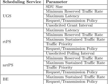
The module supports the four scheduling services (UGS, rtPS, nrtPS, BE) defined by the 802.16-2004 standard. These scheduling services behave differently with respect to how they request bandwidth as well as how the it is granted. Each service flow is associated to exactly one scheduling ser-vice, and the QoS parameter set associated to a service flow actually defines the scheduling service it belongs to. Table 2 lists the mandatory QoS parameters defined by the stan-dard that must be supported by a scheduling service. When a service flow is created the Uplink Scheduler calculates nec-essary parameters such as grant size and grant interval based on QoS parameters associated to it. For the real-time ser-vices (UGS and rtPS) the BS then allocates grants/polls on regular basis, based on the calculated interval. For the non-real-time services (nrtPS and BE) only minimum reserved bandwidth is guaranteed, if available after servicing real-time flows. Note that not all of the listed parameters are currently utilized by the scheduler. Also note that currently only service flows with fixed packet size are supported. As discussed in Section 3.3.2, the standard does not
sug-Table 2: Scheduling services and suggested param-eters.
Scheduling Service Parameter
UGS
SDU Size
Minimum Reserved Traffic Rate Maximum Latency
Request/Transmission Policy Unsolicited Grant Interval
rtPS
Maximum Latency
Minimum Reserved Traffic Rate Maximum Sustained Traffic Rate Traffic Priority
Request/Transmission Policy Unsolicited Polling Interval nrtPS
Minimum Reserved Traffic Rate Maximum Sustained Traffic Rate Traffic Priority
Request/Transmission Policy
BE Maximum Sustained Traffic Rate
Request/Transmission Policy
gest any scheduling algorithm for the schedulers. The im-plemented schedulers work based on a simple priority-based FCFS (First Come First Served) algorithm. For the uplink scheduling, priority is given starting from highest priority scheduling type to the lowest priority one (UGS > rtPS > nrtPS > BE). Among the flows of same scheduling type, pri-ority is given on FCFS basis. For the BS and SS (outbound) schedulers, higher priority is given to the initial ranging and management connections, i.e., broadcast > initial ranging > basic > primary > UGS > rtPS > nrtPS > BE. Following is a brief overview of the implemented scheduling.
UGS Scheduling
UGS (Unsolicited Grant Service) is designed for real-time applications with fixed packet size. It guarantees bandwidth on real-time basis, by allocating the flow UL grants on reg-ular basis. The key parameters for this service are toler-ated jitter, maximum latency and minimum reserved traf-fic rate. The tolerated jitter parameter specifies the maxi-mum tolerated delay variation and maximaxi-mum latency spec-ifies the maximum delay between arrival and forwarding of the packet (at the BS side). The Minimum reserved traffic rate parameter specifies the minimum bandwidth (in bps) that must be reserved for the flow. These parameters are supplied by the user while setting up the service flow. Based on these parameters, the BS calculates the interval, called unsolicited grant interval, when the service flow must be al-located a grant. The Downlink Scheduler, while scheduling UGS traffic, must ensure that the latency requirements of the flow are met. Every time the scheduler is invoked, the queues are refreshed and packets whose latency deadlines have elapsed are dropped.
rtPS Scheduling
rtPS (Real-Time Polling Service) is designed for real-time applications with variable packet size, and is ensured UL grants on periodic basis. For a rtPS flow, the BS polls the SS with a special grant, referred to as request opportunity, allowing it to send bandwidth request. The BS in response allocates sufficient bandwidth (see Section 3.3.7 for details)
in the subsequent frames. This mechanism enables the SS to specify the size of the grant, to meet flow’s variable size traffic needs. However, compared to UGS, rtPS incurs more overhead due to the bandwidth request packets. The key parameters for rtPS service are maximum latency and min-imum reserved traffic rate. The BS, based on these parame-ters, calculates the polling interval (unsolicited polling inter-val ). The Uplink Scheduler ensures the flow of the minimum bandwidth. Like UGS, the Downlink Scheduler makes sure that the latency requirements of the flow are met.
nrtPS Scheduling
The only difference between rtPS and nrtPS (Non-Real-Time Polling Service) is that the latter is designed for non-real-time applications. nrtPS flows are not polled on pe-riodic basis and instead only when sufficient bandwidth is available. SS then specifies the size of the grant through the bandwidth request packet and BS responds by allocating sufficient bandwidth only when available. However the BS ensures the flow of the minimum bandwidth (based on min-imum reserved traffic rate parameter) by periodically mon-itoring total bandwidth granted to the flow. Currently this period is set to one second. nrtPS does not use the maximum latency parameter.
BE Scheduling
BE (Best Effort) service, as the name suggests, is designed for the low priority best effort applications. For a BE flow, the scheduler allocates bandwidth only when sufficient band-width is available after servicing higher priority flows. No minimum bandwidth is guaranteed for this service.
3.3.7
Bandwidth Request and Grant Mechanism
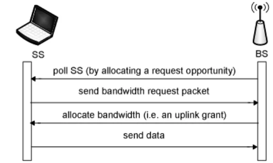
Bandwidth request and grant mechanism is a key feature of the WiMAX MAC since all three non-UGS scheduling types explicitly request for bandwidth by sending a band-width request packet. The bandband-width request and grant mechanism is implemented through the Bandwidth Manager components of BS and SS.
The mechanism works as follows. An SS with rtPS, nrtPS or BE flow is polled by the BS, by allocating it a request opportunity, on periodic basis. A request opportunity is ba-sically a UL grant, directed towards SS’s Basic CID, however it cannot be used to send data packets. It is distinguished (from regular UL grants for data) by the predefined most robust burst profile that must be used to send bandwidth re-quest in it. The size of this grant is fixed, allowing sufficient bandwidth to send a bandwidth request packet. A band-width request packet includes a special Bandband-width Request Header. The BR field of this header is used to notify the BS the requested bandwidth (in units of bytes). As the SS receives a poll, the SS Scheduler iterates through SS’s non-UGS flows and for a flow with pending packets, it sets the BR field to the size of the packet in front of the queue. CID field of the header is set to flow’s CID. The bandwidth re-quest packet is then sent and the BS responds by allocating sufficient bandwidth in subsequent frames. Figure 6 illus-trates the main steps of bandwidth request/grant process. The inclusion of Bandwidth Request Header is mutually ex-clusive with Generic MAC Header. The standard defines an optional piggyback request feature that allows sending band-width request piggybacked with data. However this feature
is not supported in our implementation.
poll SS (by allocating a request opportunity) send bandwidth request packet
SS BS
allocate bandwidth (i.e. an uplink grant) send data
Figure 6: Bandwidth request/grant process. As discussed above, bandwidth is always requested on a per flow basis but granted on per SS basis. The SS Scheduler then decides which flow shall send its data in the given grant. For the UGS and rtPS flows, the scheduler utilizes the un-solicited grant interval and unun-solicited polling interval pa-rameters, respectively, by selecting the flow whose interval is closest to elapse. The non-real-time services (nrtPS and BE) are serviced only if sufficient bandwidth is left. Since all SSs with at least one UGS service flow are au-tomatically allocated grants to service their UGS traffic, if such an SS has a non-UGS flow, it must notify this to the BS in order to be polled to send bandwidth requests. This is done by setting the poll-me field of a special type of subheader, called Grant Management Subheader. This sub-header is included together with the Generic MAC Header. The BS upon receiving a UGS packet with the poll-me field set, starts polling the SS for non-UGS flows.
3.3.8
MAC Queue
As discussed in Section 3.3.4, each connection maintains its own transmission queue. In order to support a number of MAC specific features, the module implements its own spe-cialized queue (class WimaxMacQueue in Figure 2). This queue data structure supports storing packets and headers separately, enabling the schedulers to determine in advance the CID of the connection a packet will be sent on, without dequeueing the packet, by peeking the header. Header is ap-pended to packet only when packet is dequeued and is about to be sent, following the scheduling phase. Furthermore, in order to implement the bandwidth request/grant mecha-nism, the queue data structure is designed to support both types of packets, the regular packets and the bandwidth re-quest packets. As discussed in Section 3.3.7, the two packet types contain two different types of headers. Note that the queue still functions in FIFO (First In First Out) fashion for both types of packets, in that the queue is iterated and the first packet of the respective type is accessed/dequeued. Also note that this functionality is only used by the SS, as the BS does not send bandwidth request packets.
3.4
The PHY Layer
The module provides two different versions of the PHY layer. The first is a basic PHY implementation which simply for-wards bursts received by the MAC layer ignoring any under-lying PHY layer details. Class SimpleWimaxPhy in Figure 2 represents this simple PHY layer. The second is the OFDM
PHY layer based on the WirelessMAN-OFDM specification, represented by class OfdmWimaxPhy in the figure. Since the OFDM PHY deals with the channel encoding blocks (or FEC blocks), packet bursts are converted to bit-streams and then splitted into smaller FEC blocks. The PHY currently works at 5 GHz license-free band assuming 20 MHz channel bandwidth and a 10 milliseconds frame following the param-eters used in [15]. This results in OFDM symbol duration of 13.89 µs, hence 720 symbols per frame. Table 3 lists the key PHY parameters.
Table 3: OFDM PHY parameters.
Parameter Calculation Value
Frequency band 5 GHz Frame duration 10 ms Bandwidth BW 20 MHz Carriers NF F T 256 Data carriers 192 Sampling factor n 144/125 Sampling frequency Fs n.BW 23.04 MHz Subcarrier spacing f ∆ Fs/NF F T 90000 G Tg/Tb 1/4
Useful symbol time Tb 1/f ∆ 11.11 µs
Cyclic Prefix time Tg G.Tb 2.78 µs
OFDM symbol time Ts Tb+ Tg 13.89 µs
PS duration 4/Fs 0.1736 µs
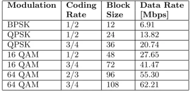
The PHY utilizes an external OFDM PHY module [12], which implements the fundamental phases of the OFDM PHY layer following the specification. This module utilizes external mathematics and signal processing library IT++ [5]. The FEC blocks are forwarded to this module which then performs the fundamental operations of channel en-coding, randomization, interleaving and modulation etc, and transmits it to the channel (and the reverse process at the receiving side). In this respect the OfdmWimaxPhy class also serves as an interface to this external OFDM module. WirelessMAN-OFDM PHY supports seven modulations to-gether with FEC coding rates. Table 4 lists these modula-tions with the corresponding data rates.
Table 4: Modulation and coding rates and corre-sponding data rates.
Modulation Coding Block Data Rate
Rate Size [Mbps] BPSK 1/2 12 6.91 QPSK 1/2 24 13.82 QPSK 3/4 36 20.74 16 QAM 1/2 48 27.65 16 QAM 3/4 72 41.47 64 QAM 2/3 96 55.30 64 QAM 3/4 108 62.21
3.4.1
Operation
The OFDM PHY layer works as follows. Once it receives a packet burst from the MAC layer, this burst is converted into a plain stream of bits. This bit-stream is splitted into smaller FEC blocks depending on the modulation scheme currently being used. Table 4 lists block sizes for the seven modu-lations as defined by the standard. These blocks are then
forwarded to the OFDM module one by one. The OFDM module performs the fundamental PHY operations on the block and forwards it to the channel layer which transmits the block. The PHY layer at the receiving side then per-forms the reverse operations of concatenating the blocks to bit-stream and converting it back to packet burst. The burst is then forwarded to the MAC layer.
3.4.2
Design
The design of the PHY layer facilitates addition of new PHY layers in future. As seen in Figure 2, WimaxPhy is defined as an abstract class and must be extended to add a new PHY implementation, as currently done for simple PHY and OFDM PHY implementations. Similarly, WimaxChannel provides abstract implementation of the channel, to allow addition of PHY-compatible channel. Currently the sim-ple PHY imsim-plementation uses the compatible Simsim-pleWimax- SimpleWimax-Channel, which transmits packet bursts, and the OFDM PHY uses OfdmWimaxChannel, which transmits FEC blocks. This design enables users to easily plug-in or switch to dif-ferent PHY layers from the simulation script.
4.
LIMITATIONS AND FUTURE WORK
The module currently lacks a full implementation of the clas-sifier as well as support for fragmentation and de-fragmentation of PDUs. Due to the lack of classifier, the module currently allows simulating only one service flow per SS. A classifier is used to map incoming packets to appropriate connections (or service flows) based on a set of criteria. An incoming packet from higher layer does not contain sufficient infor-mation to map it to a service flow of a particular scheduling service. To make it work some updates needs to be done in conjunction with the higher layers, particularly the Applica-tion layer. It should be noted that due to these complexities, none of the available WiMAX modules discussed in Section 1 implements a full, standard-complaint classifier.
IP over IEEE 802.16 [16] is a much highlighted area of dis-cussion ever since the release of the standard. One of the key issues when deploying IP over IEEE 802.16 networks is how to configure an IP Subnet over a MAC which is essen-tially connection-oriented and point-to-point. Furthermore since the MAC address is not included in the IEEE 802.16 frame headers, so typical usage of the Address Resolution Protocol (ARP) does not apply. Appropriate updates thus need to be done following [19] and [17] in order to make the module compliant to that. In particular, the IP and Ether-net specific subparts of the convergence sublayer has to be updated.
Currently the schedulers implement a simple FCFS based al-gorithm. The standard does not specify a definitive schedul-ing algorithm and leaves this up to the manufacturers to decide which algorithm to adopt. A lot of research is cur-rently going on this topic and a number of algorithms have been proposed. A potential future work therefore is to up-date schedulers with a more sophisticated algorithm. Sim-ilarly the bandwidth management mechanism may also be updated with a more efficient algorithm.
Work on a propagation/error model at the PHY layer is currently under way. Another future work is to add support in the BS to dynamically update burst profile information,
which is actually dependent on the implementation of the propagation/error model.
5.
CONCLUSIONS
This paper presented detailed design and implementation of an IEEE 802.16 WiMAX module for the recently released ns-3 simulator. The proposed module implements the PMP mode and two different PHY layers: a basic PHY layer that simply forwards bursts received from the MAC layer and a more complete WirelessMAN-OFDM PHY that fol-lows the standard. Module’s design thoroughly folfol-lows the object-oriented software development methodology and uti-lizes Unified Modeling Language (UML) for modeling. High attention has been put to come up with a detailed and stan-dard compliant implementation and to design an API that facilitates reusability, scalability and maintainability of soft-ware. The module implements key components of WiMAX MAC, including QoS scheduling services, link manager, ser-vice flow manager, simple priority/FCFS based schedulers, and bandwidth manager. Benefiting from the features of ns-3, the module enables detailed tracing, simulation of real TCP/IP-stack, emulation, and additions of new scenarios using the Helper API. We hope this module contributes to the scientific society and facilitates in evaluating and design-ing WiMAX systems. The paper also discussed a number of limitations of our module including absence of a full classifier to map incoming packets to appropriate connections. Future work focuses on implementation of convergence sublayer for IP over IEEE 802.16 applications and updating schedulers with more efficient algorithms.
6.
ACKNOWLEDGMENTS
The authors would like to thank Fabio Cristiani of Univer-sit`a degli Studi di Napoli Federico II and Kav´e Salamatian of LIP6 (Laboratoire d’informatique de Paris 6) for contribut-ing with their OFDM PHY work. We would also like to thank Mathieu Lacage, our colleague at INRIA Sophia An-tipolis and one of the lead developers of ns-3 project, for his valuable time and suggestions during the early stages of the development.
7.
REFERENCES
[1] IEEE Std. 802.16-2004, IEEE Standard for Local and Metropolitan Area Networks - Part 16: Air Interface for Fixed Broadband Wireless Access Systems. October 2004.
[2] DOCSIS (Data Over Cable System Interface Specification) Research Project,
http://www.cs.clemson.edu/∼jmarty/docsis.html, July 2005.
[3] IEEE Std. 802.16e-2005, IEEE Standard for Local and Metropolitan Area Networks - Part 16: Air Interface for Fixed Broadband Wireless Access Systems -Amendment 2: Physical and Medium Access Control Layers for Combined Fixed and Mobile Operation in Licensed Bands. February 2006.
[4] The Network Simulator ns-2 NIST add-on - IEEE 802.16 model (MAC+PHY). Technical report, National Institute of Standards and Technology, June 2007.
[5] IT++ - Library of mathematical, signal processing and communication routines,
http://itpp.sourceforge.net/, July 2008. [6] The network simulator - ns-2,
http://www.isi.edu/nsnam/ns/, October 2008. [7] The ns-3 network simulator, http://www.nsnam.org/,
October 2008.
[8] WiMAX Forum System Level Simulator NS-2 MAC+PHY Add-On for WiMAX (IEEE 802.16). Technical report, WiMAX Forum, July 2008. [9] A. Belghith and L. Nuaymi. Design and
Implementation of a QoS-included WiMAX Module for ns-2 Simulator. In 2nd International Conference on Simulation Tools and Techniques (SIMUTools’09). ACM, March 2008.
[10] J. F. Borina and N. L. da Fonseca. WiMAX Module for the ns-2 Simulator. In 18th Annual IEEE International Symposium on Personal, Indoor and Mobile Radio Communications (PIMRC’07). IEEE, September 2007.
[11] J. Chen, C.-C. Wang, F. C.-D. Tsai, C.-W. Chang, S.-S. Liu, J. Guo, W.-J. Lien, J.-H. Sum, and C.-H. Hung. Design and Implementation of WiMAX Module for ns-2 Simulator. In 1st International Conference on Performance Evaluation Methodologies and Tools (VALUETOOLS’06). ACM, October 2006.
[12] F. Cristiani. Simulation of WiMAX Physical Layer. Technical report, Universit`a degli Studi di Napoli Federico II, Italy, December 2007.
[13] C. Eklund, R. B. Marks, and K. L. Standwood. IEEE Standard 802.16: A Technical Overview of the WirelessMAN Air Interface for Broadband Wireless Access. IEEE Communications Magazine,
40(6):98–107, June 2002.
[14] T. R. Henderson, M. Lacage, and G. F. Riley. Network Simulations with the ns-3 Simulator. Demo paper at ACM SIGCOMM’08, August 2008.
[15] C. Hoymann. Analysis and Performance Evaluation of the OFDM-based Metropolitan Area Network IEEE 802.16. Computer Networks, Selected Papers from the European Wireless 2004 Conference, 49(3):341–36, October 2005.
[16] J. Jee, S. Madanapalli, and J. Mandin. IP over IEEE 802.16 Problem Statement and Goals. RFC 5154, April 2008.
[17] H. Jeon, M. Riegel, and S. Jeong. Transmission of IP over Ethernet over IEEE 802.16 Networks
draft-ietf-16ng-ip-over-ethernet-over-802.16-06.txt. IETF Draft, April 2008.
[18] C. Larman. Applying UML and Patterns: An Introduction to Object-Oriented Analysis and Design and Iterative Development. Prentice Hall, third edition, 2004.
[19] S. Madanapalli, S. D. Park, and S. Chakrabarti. Transmission of IPv4 packets over IEEE 802.16’s IP Convergence Sublayer
draft-ietf-16ng-ipv4-over-802-dot-16-ipcs-03.txt. IETF Draft, July 2008.
[20] L. Nuaymi. WiMAX: Technology for Broadband Wireless Access. John Wiley & Sons, 2007.