Creating Novel Mixed Reality Experiences using
existing sensors and peripherals
by
Fernando Trujano
S.B., Massachusetts Institute of Technology (2017)
Submitted to the Department of Electrical Engineering and Computer
Science
in partial fulfillment of the requirements for the degree of
Master of Engineering in Electrical Engineering and Computer Science
at the
MASSACHUSETTS INSTITUTE OF TECHNOLOGY
February 2018
c
○ Fernando Trujano, 2017. All rights reserved.
The author hereby grants to MIT permission to reproduce and to
distribute publicly paper and electronic copies of this thesis document
in whole or in part in any medium now known or hereafter created.
Author . . . .
Department of Electrical Engineering and Computer Science
December 18, 2017
Certified by . . . .
Pattie Maes
Professor
Thesis Supervisor
Accepted by . . . .
Christopher J. Terman
Chairman, Master of Engineering Thesis Committee
Creating Novel Mixed Reality Experiences using existing
sensors and peripherals
by
Fernando Trujano
Submitted to the Department of Electrical Engineering and Computer Science on December 18, 2017, in partial fulfillment of the
requirements for the degree of
Master of Engineering in Electrical Engineering and Computer Science
Abstract
Mixed Reality (MR) technology allows us to seamlessly merge real and virtual worlds to create new experiences and environments. MR includes technologies such as Virtual Reality and Augmented Reality. Even though this technology has been around for several years, it is just starting to become available to an average consumer with the introduction of devices such as the HTC Vive and the Microsoft Hololens.
This thesis consists of the design, implementation and evaluation of three projects that highlight a novel experience in mixed reality using existing sensors and periph-erals. VRoom describes a simple and novel approach to 3D room scanning using only an HTC Vive and 360 camera. Mathland is a mixed reality application that enables users to interact with math and physics using a stretch sensor, IMU and camera. ARPiano is an augmented MIDI keyboard that offers a different approach to music learning by adding intuitive visuals and annotations.
Thesis Supervisor: Pattie Maes Title: Professor
Acknowledgments
I would like to thank my advisors, Prof. Pattie Maes and Mina Khan for their guid-ance and support throughout this thesis. I started my Master’s without a particular project or idea in mind and they were instrumental in introducing me to the poten-tials of MR. I would also like to thank everyone in the Fluid Interfaces group at the Media Lab for sharing their passions and inspiring me to pursue mine.
Mathland, as described in Chapter 3 was a collaborative effort with Mina Khan, Ashris Choudhury and Judith Sirera. They helped build and shape Mathland into the tool is it today, and will continue on with its development after my graduation.
Finally, I would like to thank my mom, Marisa Pena-Alfaro, my sister, Linda Trujano, and the rest of my family for always cheering me up and giving me the confidence needed to pursue this project. I would like to thank my girlfriend, Juju Wang, for providing valuable input and constantly putting up with my rants on Mixed Reality technology. I would also like to thank my friends for providing a de-stressing environment during my time at MIT.
Contents
1 Introduction 15 2 VRoom 17 2.1 Introduction . . . 17 2.2 Current Research . . . 18 2.3 System Overview . . . 19 2.4 Implementation . . . 20 2.4.1 Capture Scene . . . 21 2.4.2 Viewer Scene . . . 21 2.4.3 PointViewer Scene . . . 23 2.5 Evaluation . . . 23 2.6 Challenges . . . 25 2.6.1 Synchronization . . . 25 2.6.2 VR Comfort . . . 26 2.7 Future Work . . . 27 2.8 Conclusion . . . 29 3 Mathland 31 3.1 Introduction . . . 31 3.1.1 Goals . . . 31 3.2 Integrated Sensors . . . 33 3.2.1 Hololens Camera . . . 33 3.2.2 F8 Sensor . . . 343.3 Design . . . 38 3.4 Sharing . . . 39 3.5 Evaluation . . . 39 3.5.1 Study results . . . 41 3.6 Challenges . . . 42 3.6.1 Hololens Development . . . 43
3.6.2 Hololens Anchor Sharing . . . 44
3.6.3 Showcasing AR Work . . . 45 3.6.4 Hardware Limitations . . . 46 3.7 Future Work . . . 47 3.8 Conclusion . . . 48 4 ARPiano 49 4.1 Introduction . . . 49 4.1.1 Goals . . . 49 4.2 Previous Work . . . 50 4.2.1 SmartMusic . . . 51 4.2.2 Synthesia . . . 51 4.2.3 Andante/Perpetual Canon . . . 51 4.3 Design . . . 52 4.3.1 Integrated Sensors . . . 52
4.3.2 Physical and Augmented Keyboard . . . 53
4.3.3 Keyboard UI/Helper classes . . . 54
4.3.4 Component Menu . . . 55 4.3.5 Sharing . . . 56 4.3.6 Unity Debugging . . . 57 4.4 Keyboard Components . . . 58 4.4.1 Chord Suggestion . . . 59 4.4.2 Keyboard Labels . . . 60 4.4.3 Song Tutorial . . . 60
4.4.4 Note Spawner and Flashy Visualizer . . . 64 4.4.5 Chord Detector . . . 65 4.5 Evaluation . . . 66 4.5.1 Study Results . . . 67 4.6 Challenges . . . 68 4.7 Future Work . . . 69 4.8 Conclusion . . . 71 5 Conclusion 73
List of Figures
2-1 VRoom system diagram. 360 Video and 3D positional data from the 360 cameras and Vive Tracker are fed into Unity in order to produce a VR application. . . 19
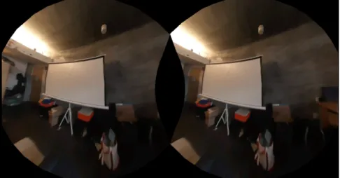
2-2 The viewer scene finds the best frame to render given the user’s position and renders it on the head mounted display. . . 22
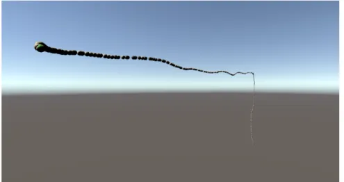
2-3 The point viewer scene renders each frame as a sphere in the 3D posi-tion in which it was captured. . . 23
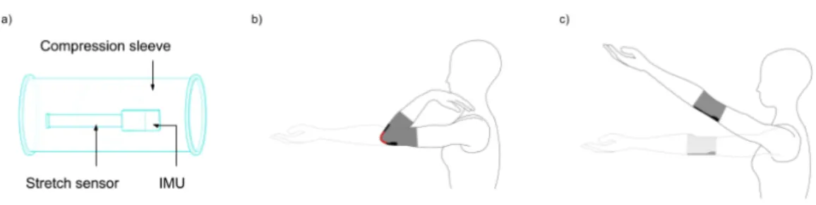
3-1 (a) Arm controller comprises of a compression sleeve that can be worn by the user. There is a figur8 sensor, which comprises of an IMU and stretch sensor. (b) and (c) Tracking user’s arm movements using the Arm controller . . . 35
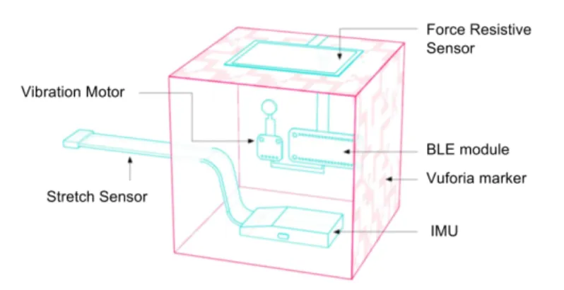
3-2 Object controller that enables tangible interactions with virtual objects in Mixed Reality. . . 36
3-3 The Microsoft Hololens headset (for MR experience) with our Object Controller and Arm Controller . . . 37
3-4 Five virtual items in Mathland’s menu to allow the user to experience different physical forces and interactions. . . 38
3-5 Three puzzles created by arranging the virtual checkpoints in MR. The left side images show the puzzle whereas the right side ones show the solution. Each puzzle corresponds to a specific physics concept: a) Circular Motion (using ball with a rope and velocity vector) b) Linear Motion (using ball with a downward Force Field, two Ramps, and a Velocity Vector) c) Projectile Motion (using a downward Force Field, and a Velocity Vector) . . . 40 3-6 Results from our survey with 30 participants. The responses were based
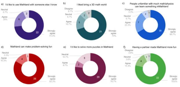
on a 5-point Likert scale: Strongly agree, Agree, Neutral, Disagree, Strongly Disagree. Charts a) to f) each correspond to one question on our post-study survey. . . 42
4-1 Multifunction knob and MIDI keyboard with AR markers on first and last keys. . . 52 4-2 Calibration ensures that the Hololens knows the exact location of the
physical keyboard. The markers show the perceived location of the first and last keys. . . 54 4-3 3D icons representing Keyboard Components are overlayed on top of
the keyboard. From left to right, the icons represent: KeyboardLabels, NoteSpawner, ChordSuggestion, ChordDetector and SongTutorial. In this figure, the NoteSpwaner component is enabled. . . 56 4-4 Non-calibration features, such as the Piano Roll can be debugged
di-rectly in Unity . . . 58 4-5 The Chord Suggestion component highlights keys that can form chords.
In this figure, both major (green highlight) and minor (pink highlight) chords are suggested with shared keys being highlighted blue. . . 59 4-6 The Keyboard Labels component augments each key by labeling it’s
corresponding note. . . 60 4-7 SpectatorView image of AR PianoRoll representation of Beethoven’s
4-8 The knob can be used to see and control the position of the song being played (left) or the speed at which it is being played (right) . . . 62 4-9 At the end of a Song Tutorial, the keyboard is transformed into a visual
representation of the user’s performance. In this graph, it is clear that the user made more mistakes in a specific section near the beginning of the song. . . 63 4-10 The NoteSpawner component emits cuboids as the user plays the
key-board in order to visualize rhythmic and tonal patterns in the song. 64 4-11 The Chord Detector component analyzes the keys as they are pressed
in order to label chords when they are played. This figure also shows how multiple components (ChordDetector and KeyboardLabels) can be enabled at once. . . 65
Chapter 1
Introduction
Mixed Reality (MR) technology allows us to seamlessly merge real and virtual worlds to create new experiences and environments. The term “Mixed Reality” was defined in 1994 and includes technologies such as Virtual Reality (VR) and Augmented Reality (AR). Even though this technology has been around for several years, it is just starting to become available to an average consumer with the introduction of devices such as the HTC Vive and the Microsoft Hololens. To make these products a reality, researchers had to devise new sensors and technologies such as Microsoft’s Spacial Understanding sensors and HTC’s Lighthouses. Until now, most research has focused on creating new sensors along with their corresponding product, but little research has been published on the use of existing sensors and peripherals in a mixed reality application. As such, there may be lost or unknown potential available in existing sensors when used in a MR application. The Leap Motion for example, initially started out as a desktop hand and finger tracker, but it’s true potential was later discovered to be in VR. The goal of this project is to integrate and explore the potential of various sensors in a MR context.
Chapter 2 describes VRoom, a simple approach to 3D room scanning using only an HTC vive and 360 camera. Chapter 3 describes Mathland, a mixed reality application that enables users to interact with math and physics in order to better learn the un-derlying concepts. Chapter 4 describes ARPiano, an augmented keyboard that offers a different approach to music learning by adding intuitive visuals and annotations. Finally, Chapter 5 concludes, and offers my closing thoughts on MR technology.
Chapter 2
VRoom
2.1
Introduction
Room-scale Virtual Reality was first introduced to general consumers in 2016 by the HTC Vive. Room-scale VR differs from traditional VR (i.e., Google cardboard, GearVR) in that it gives the user the ability to physically move within a virtual space with 6 degrees of freedom. This difference creates a much more immersive experience by allowing users to explore their virtual world by physically moving around. This technology has been mainly adopted for gaming, but it has great potential in many other applications. VRoom uses room-scale VR technology to map out an existing room in 3D space in order to allow others to experience that room from anywhere in the world.
Before making important decisions, such as the purchase of a home or physical space, people want to make sure they fully understand what they are buying. How-ever, due to a variety of circumstances, it is not always possible or feasible to be in the same physical location when making these decisions. Current solutions to this problem do not allow the user to truly get a feel for the space. For example, single photographs are commonly used for this purpose, but they fail to accurately show the room’s size and surroundings. We have recently started to see real estate com-panies incorporate 360 photography technologies to allow potential buyers to gain an even better sense of the space. These technologies could easily be expanded to a VR
headset, where a user could feel as if they were in the location of interest. While this application of 360 photography in VR does provide a better feeling of the space, all observations are done through single vantage point. The next “step up” in these technologies would be to allow the users to walk around the room and see it from different perspectives and angles.
One way to get a real room into a virtual space is to observe it and digitally recreate all aspects and components of the room using 3D modeling software. While this approach may provide an accurate representation of the space, it misses out on many of the details captured by the original space and requires a great amount of individual work in order to create the models. VRoom allows anyone to “scan” a room using a 360 Camera and a Vive tracker in order to experience that room from anywhere at any time.
2.2
Current Research
Current research on this field has focused on synthesizing frames from slightly different vantage points given frames from a single vantage point. This allows the user to better experience a 360 picture because a new frame can be synthesized as the user moves their head, allowing for depth and parallax in the image.
Uncorporeal has developed a technology which they call “holographic photogra-phy” [1]. They use a series of 20-30 images to reconstruct a three dimensional en-vironment with depth that can be viewed in VR with parallax. Similarly, Huang et al. present a system that uses a combination of structure-form-motion and dense reconstruction algorithms to reconstruct the 3D geometry of the scene [2]. They then use this scene, along with their warping algorithm to synthesize new views from a single viewpoint.
Both of these systems are able to accurately synthesize realistic frames to create a more immersive viewing experience. However, their scan coverage is limited. For example, in the Uncorporeal example, a user can only move a couple of inches in each direction before the system fades to black. VRoom provides a similar experience, but
allows the user to physically walk throughout a much larger area, up to 300 square feet (the maximum coverage of the HTC Vive trackers).
Another way to experience a physical space in VR is to create a textured 3D model using photogrammetry. This method involves taking several pictures of an object or space and analyzing the movement of various points from image to image. Google Earth for example, uses photogrammetry to construct 3D models of buildings in major cities [3]. While photogrammetry can produce an accurate representation of an object or space, the resulting model requires significant computation to produce and lacks the realness of a photograph from any given angle. VRoom aims to achieve more realistic results than photogrammetry with a simpler algorithm that requires far less computational power.
2.3
System Overview
The goals of VRoom are twofold - to easily scan a room using consumer hardware and to allow anyone with a VR headset to place themselves in that room. To accomplish this I used two Kodak Pixpro 360s and a Vive tracker. Each Kodak camera has an ultra wide lens with a 235 degree field of view. By placing two of them back to back, I can create 360 footage. The Vive tracker uses sweeps of infrared light in order to get 3D positional data with sub millimeter precision. This tracker is generally used
Figure 2-1: VRoom system diagram. 360 Video and 3D positional data from the 360 cameras and Vive Tracker are fed into Unity in order to produce a VR application.
to track hands in a VR game but for this project I attached the tracker to the 360 camera in order to get 3D positional data corresponding to each captured frame. The 360 frames, along with their positional data are fed into Unity which produces a VR application that allows a user to walk along the scanned paths of the room. A sample use case, from start to finish might look as follows:
1. User sets up the HTC Vive trackers on the room they want to scan
2. User opens the Capture scene [described in Section 2.4.1] in Unity
3. User begins recording with the 360 camera and starts the capture
4. User moves through the room, capturing different frames at different locations of interest
5. User stops the capture, stitches the 360 video, synchronizes it, and splits it into frames
6. User feeds 3D tracking data from capture scene and 360 frames into Unity to produce a VR app
7. Anyone can now experience the room that the user scanned
2.4
Implementation
VRoom is implemented in C# using Unity and SteamVR. SteamVR provides the interface to the Vive tracker and head mounted display in order to get positional data for both. The Unity application is divided into three scenes. The capture scene allows a user to scan a new room, the viewer scene allows a user to experience the room as it was scanned and the point viewer scene allows a user to visualize a particular room scan.
2.4.1
Capture Scene
The Capture Scene, as the name suggest, is responsible for capturing 3D positional data as the 360 camera and tracker move through the room. At the end of a scan, a binary file is produced that contains a mapping between frame numbers and their corresponding positions.
A scan is started by pressing the trigger on the controller which also plays a loud beep to inform the user that the scan has started. This beep assists with synchronizing the camera frames to the Unity frames. The videos are then manually extracted from the cameras and stitched together using the included software. Finally, the 360 video is trimmed to start in the same frame as when the scan started (as denoted by the loud beep) and separated into individual frames. The Capture scene also shows the current frame being captured in order to test the synchronization of the system. More details on synchronization can be found in section 2.6.1.
2.4.2
Viewer Scene
The viewer scene uses the 360 frames from the camera and the 3D positional data from the capture scene to allow a user to experience a scanned room and walk around defined paths. It does this by placing the user (a Unity camera) inside a sphere with the equirectangular frame projected onto it as a texture. SteamVR controls the user camera and links it to the user’s head movements. This way when the user turns their head, the Unity camera will turn to face a different side of the sphere in order to look at a different part of the room. This technique allows the user to view the 360 picture with all three rotational degrees of freedom.
The main innovation of the Viewer scene, and what sets it aside from a traditional 360 degree picture viewer, is that it also takes into account translational motion of the user to render new textures based on the user’s position. Upon initialization, the viewer scene loads the 3D positional data for the room from the binary file generated by the Capture scene. It uses this data to construct a KD Tree that maps frame numbers to their corresponding position in 3D space. On each frame update, the
Viewer scene queries SteamVR to get the VR headset’s position and uses the KD Tree to get the closest frame to the headset’s position. This frame is then applied to the sphere’s texture to create the illusion of movement through the room.
During early user studies (described in section 2.5), I quickly discovered that for a smooth VR experience, it is imperative that the system always react to user’s movements. This means that if a user moves towards a location where there is no new frame to show, the system still needs to react to the motion in some way. Some systems, like [1], simply fade to black as the user leaves the supported area, but I felt like this would detract from the room experience. Instead, I opted for some very primitive form of frame interpolation. If a user starts moving away from a frame, the system allows them to walk inside the sphere in which they reside. This creates an effect of objects getting closer as you walk towards them and works well as long as the user remains far away enough from the surface of the sphere. In turn, for every frame, the user’s distance and direction from the closest frame is calculated and an offset is applied to their position relative to the center of the sphere. This technique gives the user a lot more freedom to move around the room without adding too much complexity to the system.
Figure 2-2: The viewer scene finds the best frame to render given the user’s position and renders it on the head mounted display.
2.4.3
PointViewer Scene
The point viewer scene allows a user to visualize the scanned path for a particular room. The scene takes the tracking data produced by the Capture scene to render each frame as a small sphere in its true 3D position. The user can walk around this scene to get an idea of what areas of the room are scanned. Additionally, the closest frame to the user - the one that will be shown in the viewer scene is highlighted green. This feature was especially useful while debugging the application as bugs can be extremely disorienting to catch in the viewer scene. For example, at one point during development, the closet point algorithm had bugs which caused random frames to be rapidly switched. The only way to see what was going on was to wear the headset which was both uncomfortable and unfeasible.
Figure 2-3: The point viewer scene renders each frame as a sphere in the 3D position in which it was captured.
2.5
Evaluation
I evaluated each of the three scenes described in section 2.4 in terms of their comfort level, performance, and best practices. The evaluation was done by me at several stages of the project and through a formal user study near the completion of the project.
I ran the system on a desktop PC with an Intel Core i5 7600K CPU, 16GB of RAM, and an Nvidia GTX 1080 GPU with 8GB of VRAM. Scans ranged from 500 frames to 2000 frames. Performance was not an issue with this particular build as the system was able to fetch and render new frames at the required 90 frames per second. Additionally, thanks to the sub-millimeter tracking provided by the HTC Vive, the scans themselves where accurate and to scale. For example, when viewing my room virtually while in the same physical room, I was able to feel different pieces of furniture as I moved around in the virtual scene.
Throughout the project, I evaluated and tweaked the Capture Scene in order to get sharper, more accurate scans of a room. I experimented with different paths of scanning including waving the camera up and down as I walked through the room, and straight lines at different speeds. Waving the camera allowed me to get multiple frames at different heights in a single sweep but the captured frames were blurry because of the constant motion of the camera. Straight lines worked well when viewed, with slower lines allowing for finer fidelity when walking since more frames were captured. However, a single straight line limits the overall scan coverage of the room. The best scan method was a combination of straight lines around the room, as it allowed for smooth experience when walking through each line while maintaining a greater scan coverage of the room.
The user study focused on evaluating the viewing aspect of VRoom, that is the Viewer Scene and the PointViewer Scene. I instructed participants through several scans, while changing variables such as frame interpolation and sphere size. I then let users roam freely through a variety of scans, emphasizing the importance of making verbal comments as they explored the room. The point viewer feature felt natural to all participants and allowed them to quickly see which parts of the room were "sup-ported" in the current scan. Additionally, every participant reported a much more comfortable experience when frame interpolation was turned on. For the scanned room, a sphere radius of 5 (unity Units) seemed to provide the most realistic frame interpolation.
non-adjacent frames but were surprisingly pleased with the comfort level and realism when walking along the defined path. An interesting observation from this part of the study is that more frames does not necessarily mean a smoother experience. My initial assumption was that the more frames there are, the more likely it will be to find the best frame to display given the user’s current position. However, due to slight variations in height, orientation and lighting inherent to the capturing phase, the transition between close frames that were shot at different times was less smooth than the transition between sequential frames.
2.6
Challenges
Working with Unity and SteamVR was relatively straight forward. Documentation for both was easy to find online and I did not notice any mayor discrepancies between the code and documentation. However, there were a couple of other aspects of the project that proved to be more challenging, namely synchronization and VR comfort.
2.6.1
Synchronization
VRoom consists of several detached components that must be perfectly synchronized in order to provide a smooth experience. First, the two 360 cameras must be syn-chronized to each other with frame accuracy. If the footage of one camera is a couple of frames off from the other, the resulting stitched image will not be accurate or smooth. The Kodak Pixpro cameras include a remote that is supposed to start and stop both cameras at the exact same time. However in my tests, the cameras started at the same time but did not end together. This confused the stitching software and produced inaccurate scans. To fix this, I relied on the loud beeps produced by the capture scene to make sure both cameras were synced before stitching.
The stitched 360 video and the captured 3D positional data are also initially detached and must be synchronized with each other to ensure that the positions for each frame actually match up with where they were taken. To make sure both the camera and the Unity tracker started capturing data at the same time I began the
recording on the camera first, and trimmed the stitched footage to start on the same frame that the beep from the Capture Scene starts. The main challenge to ensure synchronization between the Unity Capture Scene and the camera recordings had to do with frame rates. The cameras record at 29.97 frames per second while Unity in VR runs at 90 frames per second. Unity usually allows developers to change the native frame rate but this setting is ignored for all VR applications, presumably to ensure that users have a consistently smooth VR Experience. I found a couple of “hacks” online that force Unity to run at a given frame rate. While these hacks did indeed change the frame rate, they were not precise enough for my use case. Instead of staying at each frame for .03336 seconds (the amount of time required to achieve a frame rate of 29.97), Unity would often overshoot to numbers as high as .034 seconds. While this small difference may seem insignificant, it quickly adds up over many frames. For example, in one test case by the time Unity thought it was capturing frame 1000, the cameras were actually shooting frame 1020. This frame irregularity essentially rendered the scan useless since the captured frames did no longer have the correct position assigned to it. I dealt with this issue by modifying the frame rate hacks to account for each frame overshoot and offset the next frame accordingly. These changes were tweaked over time as I did more synchronization tests.
To test synchronization I set the Capture Scene to show the current frame on the screen as it was capturing. I then started recording the screen while a scan was in place. After stitching and syncing the videos, I was able to manually check that the frame shown on the screen matched the actual frame number shot by the camera. While a discrepancy of a couple of frames every so often is acceptable, recorded frames should not start deviating from scanned frames (indicating that one medium is recording at a slower speed than the other).
2.6.2
VR Comfort
The second challenge had to do with comfort while using the VR application. Several studies, such as [4] and [5] have concluded that motion sickness in VR is caused by conflicts between the visual and vestibular systems. Therefore, it is extremely
important that a user’s motion gets accurately reflected in the virtual environment as quickly as possible.
The most expensive operations when viewing a room scan are the closest neighbor calculation and the frame fetch. I realized that in order to support scans consisting of thousands of frames while still maintaining the speed needed to have a smooth VR experience, a simple linear scan through all the frames would not work. To overcome this issue, and gain significant performance, I looped over all frames once upon ini-tialization in order to construct a KD tree. The KD tree allows me to search for the closest point to the headset in O(log n) time, compared to the O(n) time a linear search would take. This is a significant improvement considering this operation must occur 90 times a second. For frame fetching, I decided to split the video into individual jpeg frames since my initial tests showed improved random fetch performance com-pared to seeking frames from a video. With these two improvements implemented, VRoom is able to offer a comfortable experience, though more improvements can certainly still be made, as described in section 2.7.
2.7
Future Work
VRoom is noticeably more immersive compared to a single 360 picture and can cover a much greater space than current research. However, there are several areas that could improve the overall experience.
First, as described in section 2.4.2, the current implementation of frame interpola-tion is very basic. It would be interesting to apply current frame synthesis techniques to each frame, such as the ones described in [1] and [2]. The key challenge here is being able to synthesize new frames quickly enough to keep up with the 90 frames per second required for VR. This improvement would provide a more immersive and comfortable experience when deviating from the scanned path. To maximize com-fort, transitions between synthesized frames and real frames should be as smooth as possible as well.
a smooth experience. The main barrier to synchronization with the current imple-mentation is that the captured 360 frames are initially detached from the captured positional data. These are then manually reattached and synced for each room. A better solution to this problem would remove this detachment and capture both the video and positional data from the same device. This could be achieved by hooking up the HDMI out port of the cameras to a USB capture card. Unity could interface with this card in order to record the frames and position data at exactly the same time. This would provide better synchronization while making the capturing process easier.
A main advantage of VR is the ability to show each eye a different image. This is used by many games and applications to create the illusion of depth. VRoom currently shows the same image to both eyes but a more immersive experience would show a slightly different image to each eye in order to make each frame appear 3D. While regular (non-360) 3D photos require two cameras, 3D 360 photos requires a rig of four 360 cameras in order to get 3D information in all directions. This addition would further complicate the capture process and double the number of frames that need to be fetched, but it could greatly increase the immersiveness of the application. During the user study, some users noticed that the view seemed shaky even when they walked straight. This is expected given the scans are currently done by hand. A smoother experience could be achieved by applying video stabilization to the captured frames. This would require stabilizing 360 frames which is much more complicated than scanning non-360 frames, as explained in [6] and [7]. It is also important to apply the same, or a similar smoothing algorithm to the captured data itself since not doing so could reintroduce the shakiness into the final view.
The current scanning method relies on a person manually scanning the room. This method introduces many slight variations in height, roll, pitch and yaw while the camera moves through the room. Also, the person scanning the room appears in each of the frames which detracts from the room experience. The current scan method could be greatly improved by using small autonomous drones. The drones would be small enough to be automatically removed from each 360 frame and would
be much more accurate at maintaining a steady camera than a human.
2.8
Conclusion
VRoom is able to leverage room-scale VR technology and a 360 camera in order to map out different frames of a room in three dimensional space. A user can then move through this space in order to see the room from different vantage points, creating a more clear sense of scale than a single 360 picture. VRoom allows anyone to experience a real room in virtual space from anywhere in the world. This technology could be used in fields such as real estate and tourism in order to provide a better sense of a space without being physically present.
Chapter 3
Mathland
3.1
Introduction
Mathland is a mixed-reality application that augments the physical world with inter-active mathematical concepts and annotations. Through the use of an IMU, stretch sensor, haptic motor and camera, Mathland opens up new opportunities for mathe-matical learning in an immersive environment that affords situated learning, embod-ied interaction and playful cognition. Mathland was created as a joint effort between Mina Khan, Ashris Choudhury and Judith Sirera with Mina Khan having initially conceived the project.
3.1.1
Goals
It is believed that by confining mathematics education to textbooks and timed tests, schools not only take the fun and creativity out of mathematics, but also limit the educational value of mathematics [13] and contribute to the widespread problem of mathematical anxiety [11, 12]. Science in particular is difficult for students to understand due to the lack of real-life visuals such as forces acting on an object [14]. We use Mixed Reality to render 3D visualizations and utilize our integrated sensors to control objects and instantly see the results of different forces acting on an object. Mathland aims to make learning mathematics fun by enabling users to
explore and experiment with mathematical objects in their real world. Mathland accomplishes these goals by combining situated learning, embodied interaction and playful cognition.
Situated Learning
Simply put, situated learning refers to learning in your environment. In traditional schooling, students learn from a textbook which does not match their real three di-mensional environment. We use MR to bring the visualizations to the real world while the integrated sensors allow users to intuitively change parameters. Furthermore, we use the spatial mapping capability of Hololens to bring the real world environment into the virtual world so that virtual objects may interact with the real environment. For example, a virtual ball can bounce off a real wall. Bringing the real world en-vironment into the virtual world opens up really unique opportunities as the virtual world does not have to be bound by real physical laws. Using the real environment in the virtual world, a user can, for example, experience what it would be like if their room was on Mars. Research suggest that cognition is intrinsically linked to people’s physical, social and cultural context [15, 16, 17]. Situated learning ties a person’s learning to their context such that learning is inseparable from a user’s activity [18]. Mathland allows for a unique form of situated learning as the users learn in their real environment using real objects while not being limited by only real world possi-bilities.
Embodied Interaction
Cognitive processes are tied to not only people’s context, but also to their interac-tion with their physical environment [19, 20]. Body movements such as gestures are considered cross-modal primes that facilitate the retrieval of mental or lexical items [21]. Mathematical ideas, in particular, have been connected to bodily experiences [30], and research suggests that at least some mathematical thinking is embodied [22]. Students show improved math performance when user’s gestures are in line with their mathematical thought process [23]. Mathland supports embodied interaction through
the camera-based Object Controller and the wearable IMU-based Arm Controller (see Section 3.2.2).
Playful Learning
Research has shown that playful activities can support and enhance learning [24, 25]. Gee writes that kids experience a more powerful form of learning when they play games compared to when they are in the classroom [26]. In computer games, learning occurs as a result of the tasks involved in games, and user’s skills develop as they progress through the content of the game [27]. It has also been shown that students who learn using games in math class outperform the ones who do not [28].
Mathland enables playful learning by including a Puzzle experience in which users must make the ball travel through a series of ordered checkpoints using the available objects (described in Section 3.3). Both solving and creating Mathland puzzles chal-lenges users to think carefully and creatively about the menu objects available and thus encourages constructionist learning in a playful and interactive mathematical environment.
3.2
Integrated Sensors
Mathland allows the users to move, rotate, and resize objects in the virtual world. Additionally, Mathland can track a user’s arm to support embodied interactions, such as throwing a ball. In order to support the interactions required to create mathland we had to integrate with several existing sensors and peripherals. We used the Hololens camera and AR markers for 3D positioning, an IMU and stretch sensor for rotating, resizing and arm tracking, and a haptic motor for feedback.
3.2.1
Hololens Camera
The Hololens comes equipped with a built in 720p camera that allows a user to capture POV videos and pictures of the holographic words. In Mathland, we use this camera to detect a Multi Target Vuforia marker in 3D space. This allows the user to position
any object in their virtual world by simply moving the tracker to the desired location in the physical world. Additionally, we used the Hololens camera to detect and track simple objects using OpenCV. This allows us to track a real ball in real-time and trace its speed and trajectory in the real world.
3.2.2
F8 Sensor
Figur8 is a startup based in Boston that creates Bluetooth Low Energy (BLE) trackers for use in body analysis in physical therapy [31]. The device works by combining a 6 axis IMU with a capacitive stretch sensor and BLE radio for transmitting the data to a phone. We partnered with figur8 for this project and were able to integrate their trackers with Mathland.
While figur8 provided the hardware necessary to get rotation and stretch data, they only had software written to interface their trackers with iOS. We needed the BLE device to interface with a Universal Windows Platform (UWP) (which Hololens uses). To do this, I researched the BLE specifications and got the relevant GUIDs for services and characteristics of the sensor. Integrating BLE with a UWP application was not straightforward as the Windows Bluetooth libraries are fairly new and not well documented. Additionally, Unity and the Hololens run different versions of the .NET platform which further complicates the integration as the Bluetooth library is only supported on newer .NET platforms.
When connected, the figur8 sensor begins transmitting the rotation data (in Quaternions) and the stretch data (as in integer) to the BLE server. The rota-tion data needs to be further processed in order for the integrated IMU to match the orientation of the device itself. I did this by multiplying the raw Quaternion with multiple quaternion offsets, which were obtained through trial and error, and with help of figur8 engineers. The stretch data ranges from 0 to 100 depending on how much the sensor is stretched. This integer did not need any further processing and
Figure 3-1: (a) Arm controller comprises of a compression sleeve that can be worn by the user. There is a figur8 sensor, which comprises of an IMU and stretch sensor. (b) and (c) Tracking user’s arm movements using the Arm controller
Arm Controller
I was able to bring a user’s real arm into the virtual world by attaching one figur8 sensor at the elbow joint using a compression sleeve (Figure 3-1a) such that the sensor gets stretched as the user bends their arm (Figure 3-1b). I further processed the IMU data and mapped it to the rotation of the shoulder of a virtual arm and mapped the stretch data to the bend of the elbow. This allows the virtual arm to precisely follow the movements of the user’s arm.
For calibration with users of different heights, the arms starts extended downwards in a fixed position. The user is then instructed to “walk into” the virtual arm so that it matches up with their real arm while they turn on the sensor. This permanently attaches the arm to the user by keeping the distance between the Hololens and arm fixed as the user walks around the space. A correctly calibrated arm allows the user to walk around the space while using their virtual arm to interact with virtual objects. This calibration technique also allows the user to fix the arms to different locations relative to their head, effectively “extending” their arm in the virtual world.
For Mathland, we used the arm controller to bridge the gap between the real and virtual worlds and allow for embodied learning. The arm is able to interact with the virtual objects and throw balls, for example. Furthermore, since the arm is virtual, it does not have to be constrained by human or physical constraints. For example, the arm could be made much larger and stronger so that the user can pick up much larger virtual objects (such as a car) using their real arm.
The Arm Controller is novel in this field as unlike traditional VR controllers, it does not rely on external trackers or require the user to hold a bulky controller in their hand. This allows the user to forget about the controller and interact with the virtual objects in a more natural way.
Tangible Object Controller
The Tangible Object controller allows users to move rotate and resize objects in an intuitive, tangible way. It uses a figur8 sensor housed inside an AR marker cube (Figure 3-2). The Object Controller can be “attached” to any object in the scene using voice commands. After attaching the controller to an object, any modifications done to the controller will be represented on the virtual object. As mentioned above, I used the Hololens camera and multi-target Vuforia marker to detect the three-dimensional position of the Object Controller as the user moves it around 3D space. Furthermore, I mapped the IMU and stretch data from the figur8 sensor to the rotation and scale of the object, respectively.
Since there is no correct way to hold the Object Controller, additional processing of the IMU data needs to be make in order to ensure smooth rotations. When the Controller is first attached to an object, the Quaternion rotation of the Controller is queried and its inverse is calculated and stored. Then, any future sensor Quaternion rotations are multiplied by the stored inverse before being applied to the virtual
ob-Figure 3-2: Object controller that enables tangible interactions with virtual objects in Mixed Reality.
ject. This simple calculations makes the rotation steady when the controller is first attached (since multiplying the rotation by mappedRotation = currentRotation * Quaternion.Inverse(initialRotation) = Quaternion.Identity if currentRotation = ini-tialRotation) and all rotations are relative to the initial rotation of the controller.
The Object Controller is novel as it does not require any additional sensors for positioning and allows for very intuitive interactions with objects - to rotate an object you rotate the controller, to stretch and object you stretch the controller, etc. Because the output of the controller (moving, stretch, rotating of virtual object) is so closely aligned to the input of the controller (moving, stretch, rotating of the controller) these interactions also provide much better haptics and feedback than other solutions in the market today.
Controller Haptic Feedback and Vibration Motor
The Object Controller also contains a Force Resistive Sensor (FSR) and a vibration motor. The FSR is used to register when the user grasps an object to allow a user to select an object without using voice commands. The vibration motor is powered by Adafruit’s Haptic Motor Controller and can provide feedback to the FSR input. The FSR and haptic motor are connected to a Feather BLE Module, which can interface with the Hololens using similar code as the figur8 sensor.
Figure 3-3: The Microsoft Hololens headset (for MR experience) with our Object Controller and Arm Controller
3.3
Design
The Arm and Tangible Object Controllers were used to create Mathland (Figure 3-3). Using MR on Microsoft Hololens, we allow the users to see the world through a mathematical lens and immerse themselves in an interactive mathematical play-ground. Mathland is implemented as a Universal Windows Program using Unity 5.6.2 and Visual Studio 2017. Additionally, we used Holotoolkit-Unity, OpenCV, Vuforia, and the Windows Bluetooth library to support our interactions. Currently, Mathland allows users to place five different types of objects (Figure 3-4). All of the objects can be rotated, resized and repositioned using the Object controller. The detailed behavior of the objects is as follows:
Force Field: The Force Field is a cube with arrows that applies a constant linear force in the direction of the arrows on all objects within its boundaries. A user can rotate the arrows to change the direction of the applied force, or resize them to change the magnitude. The Force Field can also be made full scale so that it applies a constant linear force on all objects in the virtual world. A full scale force field pointing downwards for example, can be used to simulate gravity.
Velocity Vector: The Velocity Vector is an arrow that applies an instantaneous force to an object. The Velocity Vector adds to the instantaneous velocity of any objects that comes in contact with it. Like the force field, rotating or resizing the Velocity Vector will change the direction and magnitude of the applied force, respec-tively.
Ramp: The Ramp is a simple solid object that can be used to direct the motion of the ball along a path.
Figure 3-4: Five virtual items in Mathland’s menu to allow the user to experience different physical forces and interactions.
Cube: The Cube is a simple solid object that can act as a barrier or building block.
Rope: The Rope consists of a fixed end, which can only be moved by the user, and an un-fixed end where other objects can be attached to. The rope can be used to model circular motion by applying a Velocity Vector to a ball attached to the end of the rope.
The user can use these virtual objects with the real world environment to explore their mathematical curiosities. The benefit of virtual objects is that they can respond to both virtual and real world objects, compared to the real objects, which are influ-enced by only the real objects and forces. As a result, the user can experiment with physically difficult or impossible scenarios.
3.4
Sharing
Sharing allows people to live together in Mathland. This means that everyone sees the same objects and interactions in the same physical space. This allows for collaboration in the learning process as users can reference the same virtual objects by pointing and gesturing in their real space.
Sharing in Mathland was implemented with the Holotoolkit Sharing Service, which provides an interface to broadcast custom messages to all devices in the session. The sharing component makes sure all user interactions are broadcasted to all other users so that everyone sees the same modifications to virtual objects. The Shared Anchor (described in section 3.6.2) provides a common point in the physical space so that all users see the virtual objects in the same physical location.
3.5
Evaluation
We designed a preliminary experiment to evaluate the user experience in Mathland. We used the Puzzle experience in Mathland to build three puzzles that targeted different motions, which are taught in basic Newtonian physics: Circular Motion
Figure 3-5: Three puzzles created by arranging the virtual checkpoints in MR. The left side images show the puzzle whereas the right side ones show the solution. Each puzzle corresponds to a specific physics concept: a) Circular Motion (using ball with a rope and velocity vector) b) Linear Motion (using ball with a downward Force Field, two Ramps, and a Velocity Vector) c) Projectile Motion (using a downward Force Field, and a Velocity Vector)
(Puzzle 1), Linear Motion (Puzzle 2) and Projectile Motion (Puzzle 3). Figure 3-5 shows the relative positions of the checkpoints for each puzzle. In order to solve each of the puzzles, the user had to understand the mathematics/physics concepts associated with the five virtual items in Mathland’s menu. For Puzzle 1 (Circular Motion), the user had to notice that since the checkpoints are arranged in a circular orbit, the ball needs a centripetal force. This centripetal force can be created by attaching the ball to a Rope object, and giving the ball an initial velocity that is perpendicular to the rope so that the virtual ball starts swinging in a circular motion. To solve Puzzle 2 (Linear Motion), the user could place inclined ramps between the checkpoints and create a full-scale downward Force Field to resemble gravity (since there is no gravity by default in the world, and without a downward force, the ball
does not move down the ramps). For Puzzle 3 (Projectile Motion), in addition to the downward gravity-like Force Field, the user needed a Velocity Vector to launch the ball at an angle such that it follows a parabolic path, i.e. projectile motion. The three puzzles and their respective solutions are shown in figure 3-5.
We conducted the experiment with two participants in one trial to evaluate the collaborative learning experience in Mathland. The two participants shared a common Mixed Reality world, and had a total of 30 minutes to solve all the puzzles. We gave only one Object Controller to each participant pair to encourage more collaboration and interaction between participants.
3.5.1
Study results
We had a total of 30 participants (22 female and 8 male; 8 in the age group 16-20, 21 in the age group 20-35, and 1 above 35). 28 participants performed the study in pairs and the remaining 2 performed the study individually because of scheduling conflicts. The two people in each trial were paired based on their time availability. As we were observing the study, we noticed that despite some problems with the Hololens, most participants were having a lot of fun. They were solving puzzles lying down on the floor, playing around with the different elements, and high-fiving each other when completing a puzzle. We presented our participants with a post-study survey, which had six five-point Likert scale type responses and three open ended questions. Figure 3-6 shows the results for the six Likert scale type responses, which can be categorized as follows:
i. Engagement: Our users were thoroughly engaged in Mathland, 28 (93.3%) out of the 30 participants agreed (20%) or strongly agreed (73.3%) that they “would like to use Mathland with someone else they know” (figure 3-6a). Moreover, 26 (86.6%) of our participants agreed (25%) or strongly agreed (70%) that they “liked being in a 3D Mathland” (figure 3-6b).
ii. Learning : The participants found the puzzles to have educational value as 27 (90%) of them agreed (23.3%) or strongly agreed (66.7%) that “people unfamiliar with much mathematics/physics can learn something in Mathland” (figure 3-6c).
Figure 3-6: Results from our survey with 30 participants. The responses were based on a 5-point Likert scale: Strongly agree, Agree, Neutral, Disagree, Strongly Disagree. Charts a) to f) each correspond to one question on our post-study survey.
iii. Problem-solving: All of our participants not only solved all three puzzles, but also enjoyed solving those puzzles. 29 (96.6%) of them agreed (13.3%) or strongly agreed (83.3%) that “Mathland can make problem-solving fun” (figure 3-6d), and 25 (83.3%) agreed (6.7%) or strongly agreed (76.7%) that they “would like to solve more puzzles in Mathland” (figure 3-6e).
iv. Collaboration : During the study we observed that partners collaborated effectively to problem-solve. In the post-study survey, out of the 28 participants who did the study with another partner, 26 (92.8%) agreed (14%) or strongly agreed (78.6%) that they “having a partner made Mathland fun” (figure 3-6f).
3.6
Challenges
Developing Mathland posed different challenges - mostly related to developing on a still evolving environment like the Hololens. The first hurdle involved getting used to a new environment with unusual deployment and debugging methods. Another challenge was making sure that all players share the same coordinate system so that they can see the virtual objects on the same location. Lastly, we had to build a
3.6.1
Hololens Development
The Hololens developing environment is constantly evolving to better fit the needs of developers. Hololens runs applications on the Universal Windows Platform, which can be built by Microsoft Visual Studio. Unity is used as the main game engine and packages such as HolotoolKit-Unity greatly help with managing the Hololens essentials such as Spatial Mapping and Sharing. However, many other libraries such as Obi Solver (for physics simulations) were not supported in this platform. Since this environment is still relatively new, it suffers from some issues not present in more established environments like Android and iOS.
Deployment for example, consists of a two step process where a Visual Studio Solution must be created from Unity first before it can be deployed to the Hololens. This extra step slows down developing as two build processes must complete for each test iteration. Additionally, there are times where deployment to the Hololens will inexplicably fail and the build process must be started over. This two step process of deployment also makes it harder to debug as debug/crash statements don’t have an associated filename or line number.
The Hololens environment is also rapidly changing. For example, the tools we used to build the application were deprecated by the time we ran our user studies. This rapid evolvement also meant that documentation was not always caught up with the current version of the code. This was time consuming to find and fix but we were able to share our discoveries with the community through pull requests and forum answers.
Additionally, since the Hololens is aware of its surroundings via spatial mapping and wireless radios, the code can have different results in different physical spaces. For example, Anchor Sharing (see section 3.6.2) requires the 3D spatial mapping to be serialized and shared, but this process can fail depending on the surrounding location since objects like screens or glass can produce very different spatial maps on each hololens, causing them to be out of sync in one room, but not another.
We also ran into a particularly difficult bug where all five of our Hololens suddenly kept crashing on initialization while running the same code that had worked hours earlier in the same room. We reverted back several commits to no avail and even tried factory resetting some Hololens. The next day, we launched the app on a different location and had no issues with any Hololens. After several hours of debugging and frustration we discovered that the crash was caused by a rogue Bluetooth device that was sending corrupt advertisement packages. The packages would make the Windows bluetooth library crash as soon as the name of the device was queried. This explanation explains why all hololenses suddenly stopped working (the rogue device was turned on) and why everything seemed fine in a different location, outside the range of the rogue device. We patched this issue by blacklisting the BLE addresses of any device that had previously caused the app to crash.
3.6.2
Hololens Anchor Sharing
Collaboration is at the core of Mathland as solving problems with another person is proven to help both users learn the material better. In order to ensure smooth collaboration between two or more users, we needed to make sure virtual objects appear to be in the same location for all users. It is important to note the difference between the sharing component and the anchor sharing. The sharing component (described in section 3.4), guarantees that updates from one player, (ie rotating a ramp) will be propagated to all users while the anchor sharing guarantees that all users will see the ramp in the same physical location.
The first player to launch the app is prompted to place an anchor in their world. Any other players that join afterwards should be able to see the anchor in the same location. From there, the anchor library can be used to make sure objects will appear in the correct coordinates for each user. However, getting the anchor sharing to work as expected was not as straightforward as it appeared. To understand why, it is useful to know how spatial sharing actually works.
Internally, the player that places the anchor collects spatial information about the anchor’s location and serializes it before sending it to the server. Any new players
that joins then downloads this information (about 13MB), deserializes it and tries to use its own spatial mapping data to “match” the anchor location as described by the first Hololens. If a good match is detected, the anchor is placed, otherwise the app waits until it can collect enough information to get a match. Since each Hololens creates a spatial map independently, these are not guaranteed to match, specially when dealing with tricky objects like glass and with people walking around. If the first hololens describes the location of the anchor using features not present in the other hololens’s map, they will never be able to find a match and the app will hang forever.
To minimize the amount of failed matches, it was helpful to understand how the system works. First, it is important to make sure the spatial map is accurate on all hololenses before matching. This ensures that the description of the anchor location will be good enough for the other hololens to find a match. Second, the anchor must be placed around well defined features as these are sent to the other hololenses. For example, placing the anchor in the middle of a wide open space will make it much harder for the other hololens to find the right location as there are not as many features surrounding the anchor. Similarly, placing the anchor near glass will yield the same unacceptable results. Finally, during our testing, we noticed better success rates if the apps are started facing the direction where the anchor was placed.
When it works successfully, the entire anchor sharing process takes between one to five minutes, but sometimes multiple tries are necessary before getting a success-ful match. This process must be done before the core of the app can launch which dramatically decreases the speed of development. To overcome this, we initially de-veloped components independently so that we could test them without going through the long anchor sharing process.
3.6.3
Showcasing AR Work
Since the Hololens is still a new and expensive piece of technology, its availability to consumers is still very limited. As such, it is difficult to explain Mathland to people that don’t have access to the same technology. While the Hololens does include a
camera that can overlay virtual objects on top of the camera feed, the resulting quality is poor and not optimal for presentation. We used Microsoft’s Spectator View to record higher quality videos. Spectator View consists of a hardware camera rig and the compositor code. Spectator View works by having the camera and hololens both record the video feed and holograms respectively. The compositor software then takes these two inputs, applies the appropriate mathematical transformations and outputs a final video. The hardware rig attaches a Hololens on top of a camera and was fairly straightforward to build using Microsoft’s guide [29]. The compositor software requires that all app updates are shown in the Unity editor, which required some restructuring of our code. With Spectator View working, we were able to record high quality videos of Mathland [8].
3.6.4
Hardware Limitations
My initial tests revealed that unlike VR, where 3D-tracked controllers provide a smooth interaction, the Hololens relies purely on air gestures for input and does not provide 3D tracking capabilities. This limitation makes it difficult to support simple interactions in an application. Additionally, air gestures are difficult to per-form and lack the tangibility and haptics of a physical controller. To get around this limitation, we used the Hololens’s camera, computer vision, an IMU and a stretch sensor to create a Tangible Object Controller (see Section 3.2.2).
The Hololens display does a pretty impressive job at rendering objects in the scene at 720p resolution. However, the field of view of the display is very limited, at around 40 degrees. This means that you have to look around in order to see the entire scene. I purposely did not address this hardware limitation as I believe the field of view will be greatly improved in future augmented reality devices. For example, the Meta headset, which is already available to consumers, doubles the field of view of the Hololens.
3.7
Future Work
In this paper, we integrated the three key components we believe are necessary for en-abling a Mixed Reality Mathland: embodied interaction (Object and Arm controller), situated learning (OpenCV and spatial analysis), and constructionist methodologies (Newtonian puzzles and visualizations). We look forward to exploring these three areas further in the following ways:
(i) Conduct user studies to evaluate the Object and Arm controller: We evaluated the overall learning experience of users in the study mentioned in this paper, but we plan to conduct more studies to evaluate the interaction design of the Object and Arm controller in the context of Mathland as well as other MR applications.
(ii) Explore computer vision approaches to recognize 3D objects: Hololens can do generic spatial mapping for walls, ceilings, etc, but cannot detect the 3D structures of individual objects. To make Mathland more deeply connected to the real world, we plan to recognize the 3D shapes of real world objects so that the user can create 3D virtual objects by scanning real world objects.
(iii) Improve the field of view of the existing cameras: Mathland’s computer vision capabilities are currently limited to the Hololens’ camera, and thus objects outside the user’s view are not tracked. We hope to be able to track more objects outside the user’s field of view without using external trackers so that, for example, a user can bounce a real ball anywhere in the room and the full trajectory of the real ball will tracked in Mathland even when the ball goes outside the user’s field of view.
(iv) Add more learning tools: Mathland currently supports Newtonian physics concepts, but we have plans to provide more concepts related to Flatland [10] and higher dimensions in mathematics, space-time fabric and black holes, electromagnetic fields and the speed of light.
3.8
Conclusion
Technological advances often usher in educational innovations as people leverage new technologies for educational use cases. Mixed Reality has previously been used to cre-ate new educational environments, but similar to traditional learning environments, most of them have treated the learner as a passive consumer rather than active cre-ator of knowledge. In Mathland, we allow learners to unleash their creativity and curiosity in a MR physics playground, where learners can visualize, experience and explore mathematical concepts in their real world.
In order to allow for more natural interactions with virtual objects, we used exiting sensors to create custom controllers, namely an Object controller and Arm controller, which allow for more tangible and embodied interactions in Mixed Reality. We also used spatial mapping and computer vision to situate learning in the user’s real en-vironment. Our user studies suggest that Mathland could be conducive to creative learning, collaboration, and playful problem-solving.
Using constructionist, embodied and situated learning in MR, Mathland allows the users to view the world through a mathematical lens and naturally interact and experiment with mathematical concepts so that learners may develop an intuitive understanding of mathematics, as envisioned by Papert in his vision for Mathland [9].
Chapter 4
ARPiano
4.1
Introduction
This chapter describes ARPiano, a mixed reality application that augments a physical keyboard. ARPiano uses a MIDI (Musical Instrument Digital Interface) keyboard and a multi function knob to create a novel mixed reality experience that supports visual music learning, music visualizations and music understanding. ARPiano is able to precisely locate a physical keyboard in order to overlay various objects around the keyboard and on individual keys. These augmented objects are then used for music learning, visualization and understanding. Furthermore, ARPiano demonstrates a novel way to utilize the keys in a piano as an interface to interact with various augmented objects.
4.1.1
Goals
ARPiano is designed to allow for better visual music learning, music visualization and music understanding.
Music Learning
The main goal of ARPiano is to facilitate visual music learning using augmented reality. Traditional music learning focuses on reading symbols in the form of sheet
music. However, these symbols are abstract and there is no intuitive correlation between the symbol and the note that it represents. For example, notes of different lengths are differentiated by whether the symbols are filled in or not (quarter note and half notes) or whether they have an extra an extra tick attached to them (eighth notes and sixteenth notes). This notation is not immediately intuitive and requires that the user learn the symbols in order to make sense of them. Current theories of learning show that using multiple modalities in learning is an effective strategy to form mental constructs and schemas [36, 37, 38].The visual aspect of traditional music learning depends on these abstract symbols and could be stronger.
ARPiano aims to facilitate visual music learning by providing a deeper connection between the song the user is learning and what they are seeing. This is accomplished by intuitive and spatially accurate visuals, real time feedback, and performance statis-tics. ARPiano visually renders a song in the form of a sequence of cuboids where the length of the rectangle represents the length of the note and the position relative to the keyboard represents the note value.
Music Visualization and Understanding
ARPiano also allows for music visualization and music understanding. Music visual-ization is accomplished by emitting a sprite from the physical key location whenever the key is pressed. This provides the user with a visual counterpart to what they are hearing and allows them to better see patterns in the music. Additionally, while the user is playing, ARPiano is able to augment the interface to point out specific musical artifacts, such as chords, which aids in music understanding.
4.2
Previous Work
Music learning software is not a new field and there are many applications available that try to facilitate music learning by creating visuals or providing performance statistics. However, none of the applications provide spatially accurate visuals.
4.2.1
SmartMusic
SmartMusic [32] is a music learning software that provides helpful feedback on a player’s performance . A user is displayed the sheet music as well as a bar indicating the current measure that they are on. While playing a song, SmartMusic uses a micro-phone to determine whether the user is playing the correct notes. While SmartMusic provides helpful statistics to the user, such as which sections had the most mistakes, it still relies on sheet music and does not offer a more intuitive musical representation of a song.
4.2.2
Synthesia
Synthesia [33] is a piano learning software that, like ARPiano, renders songs in the form of a piano roll. Each note in the song is represented by a rectangle that slowly approaches its corresponding key on a virtual keyboard on the display. This repre-sentation is more intuitive than sheet music and allows the user to see patterns in the song. Synthesia is also able to track a player’s performance and provide statis-tics to help them guide their practice. While Synthesia provides an intuitive visual representation of the song, it does so on a traditional 2D display and requires that the user look back and forth between the virtual keyboard on the display and the physical keyboard they are playing on.
4.2.3
Andante/Perpetual Canon
Andante [34] and Perpetual Canon [35] are part of a collection of research projects developed by Xiao Xiao from the MIT Media Lab. They augment a piano with a projector and are able to provide visualizations of pre-recorded or live music. These projects did not however, focus on music learning or analyzing what is being played.
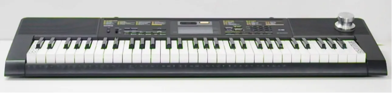
Figure 4-1: Multifunction knob and MIDI keyboard with AR markers on first and last keys.
4.3
Design
ARPiano runs on a Hololens that wirelessly receives messages from a server running on a PC. The application augments the physical keyboard with various sprites and annotations and receives input from the keyboard in order to support various inter-actions. ARPiano adopts a modular design in the form of KeyboardComponents (see section 4.4). The design of ARPiano was influenced by the Hololens development challenges encountered in Mathland. As such, sharing is done without a Spatial an-chor (section 4.3.5) and a separate Unity debugger was built along the way to speed up development (section 4.3.6).
4.3.1
Integrated Sensors
ARPiano uses a MIDI Keyboard and a multi function knob for input (Figure 4-1). Both of these devices communicate over USB. Since the Hololens does not have any USB ports, additional steps had to be taken to integrate these devices into a Mixed Reality experience. The application also uses the built in Hololens camera to get the initial position of the the keyboard in three dimensional space.
The keyboard sends MIDI commands to the computer over USB and is the main interface for ARPiano. When a key is pressed the keyboard emits the corresponding sound and sends a MIDI message to the connected computer. MIDI is well established and documented so many libraries exist to parse these messages. I used the open source MidiJack Unity plugin [42] to parse each incoming MIDI message into its