Courseware and Curriculum Development For a Wireless
Electronics Class
by
Ariel Rodriguez
Submitted to the Department of Electrical Engineering and Computer Science
in partial fulfillment of the requirements for the degree of
Masters of Engineering in Electrical Engineering and Computer Science
at the
MASSACHUSETTS INSTITUTE OF TECHNOLOGY
January 2007
©
Massachusetts Institute of Technology 2007. All rights reserved.
A uthor..
...
...
Department of Electrical Engineering and Computer Science
January 16, 2007
Certified
. .. a. ... .s ... . ... ... .... .. Steven B. LeebProfessor, MIT
Thesis Supervisor
(2
I A opCertified by...
. w- . VVE.../ ...Robert W. Cox
Assistant Professor, UNC Charlotte
Accepted by ....
Thesis
Supervisor
... .3
U
.
...
.
Arthur C. Smith
Chairman, Department Committee on Graduate Students
ARCHIVES
MASSACHUSErTS INSTITUTEOF TECHNOLOGY
Courseware and Curriculum Development For a Wireless Electronics
Class
by
Ariel Rodriguez
Submitted to the Department of Electrical Engineering and Computer Science
on January 16, 2007, in partial fulfillment of the
requirements for the degree of
Masters of Engineering in Electrical Engineering and Computer Science
Abstract
The design of basic wireless building blocks (such as oscillators, amplifiers, and modulation
circuits) and modern encoding techniques such as CDMA (Code Division Multiple Access)
are in high demand by employers of recent graduates. This thesis sets forth a lesson plan
and laboratory kit design to be used in the development of a new class that teaches these
wireless system design techniques. Such a class will help students gain both the theoretical
and practical experience required of them in today's industry.
Thesis Supervisor: Steven B. Leeb
Title: Professor, MIT
Thesis Supervisor: Robert W. Cox
Acknowledgments
Special thanks go out to my advisors: Professor Steven Leeb who taught me what it means to be a professional engineer and Professor Rob Cox whose knowledge and guidance made this thesis possible. I'd also like to thank Jim Paris for his sage-like advice on microcontroller programming. My sincerest gratitude goes out to the Grainger Foundation and Cambridge-MIT Institute for their financial support. Finally, to all those who believed in me: my family and friends; I could not have completed this without your unending love and support thank you so very much.
Contents
1 Introduction 19
2 The Laboratory Kit 21
2.1 Transmission Module . . . . 22
2.2 Reception M odule . . . . 23
3 Lab 1: Resonant Circuits, Amplifiers, and AM/FM Transmission 25 3.1 The Linear RF Power Amplifier Circuit . . . . 26
3.1.1 Buffer Input Stage ... ... 27
3.1.2 Power Amplifier Stage ... 28
3.2 The XR2206 As A Modulation Platform ... 30
3.2.1 Amplitude Modulation ... 30
3.2.2 Frequency Modulation ... 33
4 Lab 2: The Superheterodyne Receiver, and Asynchronous AM Demodu-lation 39 4.1 The Superheterodyne Receiver . . . . 39
4.1.1 Receiving Circuit ... ... 40
4.1.2 M ixer . . . . . 41
4.1.3 IF Am plifiers ... . 44
4.2 AM Demodulator ... . 46
4.2.1 Demodulating An Audio Signal ... . 49
5 Lab 3: Phase-Locked Loops, Clock Recovery, and FM Demodulation 53 5.1 PLL Overview . . . . 54
5.1.2 Loop Filter . . . . 57
5.1.3 Voltage-Controlled Oscillator . . . . 58
5.2 PLL Design and Application . . . . 58
5.2.1 PLL Design Using The CD4046 . . . . 59
5.2.2 FM Demodulation Using The LM565 . . . . 65
6 Lab 4: DSSS Broadcast Techniques Using CDMA 73 6.1 DSSS Overview . . . . 74
6.1.1 Spread-Spectrum Implementations ... 75
6.1.2 The IS-95 Standard and Its Lab 4 Implementation . . . . 80
6.1.3 Synchronization . . . . 83
6.2 Introductory MATLAB Exercises . . . . 84
6.2.1 Antipodal Versus Digital Signals . . . . 85
6.2.2 Barker Codes and Synchronization . . . . 90
6.3 Hardware CDMA Implementation . . . . 92
6.3.1 Signal and Clock Transmission/Reception . . . . 93
6.3.2 Transmission/Reception Using A Serial Communications Interface . 97 6.3.3 Serial Communication With A PC . . . . 101
6.3.4 Wireless Transmission . . . . 103
7 Lab 5: Antenna Electrodynamics 107 7.1 The LRL550B-SS Microwave Trainer . . . . 108
7.1.1 Reflex Klystron Microwave Generator . . . . 109
7.2 Antenna Electrodynamics . . . . 111 7.2.1 Pickup Circuit . . . . 112 7.2.2 Horn Antenna . . . . 114 7.2.3 Dipole Antenna . . . . 115 8 Conclusions 119 A PIC C Code 121 A.1 Clock and Signal PIC Reception Code . . . . 121
A.2 SCI PIC Transmission Code . . . . 124
A.4 SCI PIC Transmission Code With PC Communication ...
129
A.5 SCI PIC Reception Code With PC Communication ...
134
B Eagle CAD Schematics 139 B.1 Lab Kit Transmission Module Schematics .... ... 139
B.2 Lab Kit Receiver Module Schematics . . . 143
B.3 Pickup Circuit Schematic . . . . 153
C Eagle CAD Board Layouts 155 C.1 Laboratory Kit Transmission Module Layout . . . . 155
C.2 Laboratory Kit Receiver Module Layout . . . . 156
C.3 Pickup Circuit Layout . . . . 157
D Laboratory Kit Parts List 159 D.1 Transmission Module Parts . . . . 159
D.2 Reception Module Parts . . . . 161
D .3 Lab 5 Parts . . . . 163
E Typical Component Values 165 E .1 Figure 3-2 . . . . 165 E .2 Figure 3-5 . . . . 165 E.3 Figure 3-8 . . . . 166 E .4 Figure 5-6 . . . 166 E.5 Figure 5-8 . . . . 167 E.6 Figure 5-11 . . . . 167 E .7 Figure 6-18 . . . 167 E.8 Figure 7-5 . . . 168
List of Figures
2-1 Conceptual drawing of the laboratory kit "clam shell" design. . . . . 21
2-2 Photograph of the component sockets to be used in the laboratory kit. . . . 22
2-3 Diagram describing the contents of the laboratory kit transmission module. 23 2-4 Transmission module PCB layout. . . . . 23
2-5 Diagram describing the contents of the laboratory kit reception module. . . 24
2-6 Reception module PCB layout. . . . . 24
3-1 Transmission-framework block diagram for the course laboratory kit. . . . . 25
3-2 RF Linear Power Amplifier used for broadcast signal transmission. . . . . . 26
3-3 Power amplifier stage operating near the maximum output voltage. . . . . . 30
3-4 Block diagram of the canonical DSB/WC modulation system. . . . . 31
3-5 XR2206 circuit configured as an amplitude modulator. . . . . 32
3-6 Oscilloscope trace of the XR2206 acting as an amplitude modulator. .... 33
3-7 Approximate spectrum plot for a narrow-band FM signal from [5] . . . . 36
3-8 XR2206 circuit configured as a frequency modulator. . . . . 36
3-9 Oscilloscope captures of the XR2206 operating as a frequency modulator. . 37 4-1 Block diagram of the superheterodyne receiver system. . . . . 40
4-2 Complete reception antenna circuit. . . . . 41
4-3 Frequency-domain convolution of the two mixer circuit inputs. . . . . 42
4-4 Single-transistor mixer circuit. . . . . 43
4-5 Local oscillator circuit. . . . . 44
4-6 Intermediate-frequency amplifier stage . . . . 45
4-7 Intermediate-frequency amplifiers working to amplify a received signal. . . . 45
4-9 4-10 5-1 5-2 5-3 5-4 5-5 5-6 5-7 5-8 5-9 5-10 5-11
AM demodulators filter following an input envelope. . . . .
LM386 audio amplifier circuit. . . . .
50 51
Block diagram of a linearized feedback model for a phase-locked loop. . . . 54
Analog multiplier acting as a phase detector. . . . . 56
XOR phase detector working on two square wave inputs. . . . . 57
Average phase detector output voltages, multiplier and XOR. . . . . 57
CD4046 passive loop-filter block diagram. . . . . 60
CD4046 passive loop-filter circuit . . . . 63
CD4046 active loop-filter block diagram. . . . . 63
CD4046 active loop-filter circuit. . . . . 65
Block diagram of a PLL acting as an FM demodulator. . . . . 66
Pole-zero loop filter to be used for the FM demodulator. . . . . 67
LM565 FM demodulator circuit. . . . . 67
5-12 Oscilloscope captures of the LM565 acting as an FM demodulator. 6-1 Block diagram of a typical spread-spectrum communication system. 6-2 Digital and antipodal methods for spreading a data signal. . . . . . 6-3 Block diagram of the digital and antipodal despreading processes. . 6-4 Antipodal multi-user CDMA system. . . . . 6-5 Digital multi-user CDMA system. . . . . 6-6 IS-95 CDMA communication system using a BTS.. . . . . 6-7 IS-95 forward channel version to be implemented in Lab 4 . . . . . 6-8 Plot demonstrating effect of frame desynchronization. . . . . 6-9 Block diagram of the CDMA hardware system. . . . . 6-10 Complete clock-and-signal CDMA circuit. . . . . 6-11 Reception module despreading aggregate data. . . . . 6-12 6-13 6-14 6-15 6-16 6-17 Circuit schematic of the CDMA system using the built-in USART. . . Structure of the serial transmission packet. . . . . USART-based reception module despreading aggregate data. . . . . . CDMA hardware block diagram including PC communication system. MAX233 line driver circuit. . . . . CDMA circuit for wireless FM transmission . . . . 71 75 . . . . . 76 . . . . . 78 . . . . . 79 . . . . . 80 . . . . . 81 . . . . . 82 . . . . . 84 . . . . . 93 94 . . . . . 97 98 99 . 100 101 102 103
6-18 Circuit for conditioning the demodulated CDMA signal. . . .
7-1 LRL550B-SS microwave trainer . . . . 108
7-2 Simplified model of the Reflex Klystron microwave generator. . . . . 109
7-3 Rectangular waveguide dimensions. . . . . 111
7-4 Pickup circuit PCB alongside horn antenna. . . . . 113
7-5 Field-strength measurement (pickup) circuit schematic. . . . . 113
7-6 Horn antenna from two points of view. . . . . 114
7-7 Dipole antenna configuration and field-strength pattern. . . . . 116
7-8 Dipole connection to the Reflex Klystron generator waveguide. . . . . 116
List of Tables
6.1 Digital values and their corresponding antipodal equivalent values. . . . . . 77
Listings
6.1 Sample MATLAB code for spreading antipodal and digital signals . . . . . 85
6.2 Sample MATLAB code for despreading data streams . . . . 86
6.3 MATLAB code for creating an aggregate, spread signal. . . . . 88
6.4 MATLAB code demonstrating the autocorrelation of the Barker code . 90
6.5 MATLAB code using the Barker code for spreading and despreading. ... 91
Chapter 1
Introduction
Wireless systems are among the most widely used technologies by todays engineers and cir-cuit designers. As a result, employers are starting to demand more experience in these areas from new recruits. This demand is not narrow in scope. Commercial wireless technologies alone encompass a broad range of circuit theory and manufacturing techniques.
Given this wide-ranging employer demand, students need to be introduced to wireless technologies early on; at the undergraduate level. As part of their education they need to be introduced to several basic wireless electronic building blocks (i.e. amplifiers, oscillators, resonant circuits) as well as modern data transmission techniques such as those used in
CDMA communication systems.
Not only must they be introduced to the fundamental concepts underlying these tech-nologies but they also need experience applying them in real-world situations. An un-dergraduate laboratory class that surveys several wireless electronics techniques has the potential to successfully provide students with both the theoretical and practical experi-ence they need. This thesis aims to develop the equipment (laboratory kit, test equipment, etc.) and preliminary lesson plan for such a class.
Chapter 2 presents a new laboratory kit designed to be the centerpiece of the class. Labs in subsequent chapters are all based around the design and contents of the laboratory kit. The systems built into the kit feature a "permanent topology" approach to engineering and construction. This approach contrasts sharply to most solderless breadboard-based kits, but gives students the opportunity to explore more systems within one semester.
to be completed in one semester. Chapters 3 and 4 have students create the fundamen-tal transmission and reception systems for the rest of the semester. These include tuned amplifiers, AM and FM modulators, and a superheterodyne receiver system. Chapter 5 details several exploratory exercises in phase-locked loops, culminating in an FM demodu-lator circuit. Chapter 6 deals with direct sequence spread spectrum techniques such as code division multiple access methods of transmission using microcontrollers. Finally, chapter 7 delves into topics related to electromagnetics including transmission line problems, antenna patterns, and microwave generation.
Chapter 8 summarizes the intended goals of the exercises listed in the previous chapters. Additionally, the lab kit is designed with a modicum of modularity that allows for expansion of the class material. Possible areas for expansion are also discussed in this chapter.
Chapter 2
The Laboratory Kit
The laboratory kit for the course is the main platform for all of the assignments students will complete throughout the semester. It will contain all of the circuits discussed in subsequent chapters of this document. The kit will follow the design of other course laboratory kits at MIT, taking the shape of a clam shell as shown in Figure 2-1. The kit will open to reveal its two main communication units: a transmission module for broadcasting wireless signals and a reception module for receiving and demodulating signals. The two units will be separable, each having its own power supply which will allow them to work independently from each other. With these two independently operating units, students can create several different wireless communication scenarios with one or more laboratory kits.
Figure 2-1: Conceptual drawing of the laboratory kit "clam shell" design. The kit will open up and separate into its two main units: a transmission module and a reception module.
Moreover, students will not rely on solderless breadboard for the majority of the circuits constructed for each module. For example, the broadcast framework built into the trans-mission module will be built using the idea of "permanent topologies". Each major circuit
to be studied will already have its topology etched into its respective modules printed circuit
board. Students will study the specifics of each circuits design, but will not be required to
construct the final version of each circuit to be used for the rest of the semester. Instead,
all the components salient to each circuits design (e.g. resistors setting bias points, filter
components, etc.) will be replaced by sockets as shown in Figure 2-2. Students will be
required to select the appropriate components and place them in these sockets, but will not
be required to wire the circuits together. This permanent topology design approach will
minimize the time students spend in construction, without sacrificing the important
de-sign stages of building each circuit (namely selecting component values according to dede-sign
criteria).
Figure 2-2: Photograph of the component sockets to be used in the laboratory kit
"per-manent topology" design. Components critical to system design will not be soldered in
directly. Instead, they will be selected by students and placed in sockets as shown.
2.1
TYansmission Module
The transmission module will be the basis for all the laboratory assignments broadcast
and modulation components. The module will consist of 6 separate sections: a power
supply, broadcast amplifier, modulation system, CDMA subsystem, solderless breadboard,
and extension interconnects. These sections will be arranged inside the kit according to the
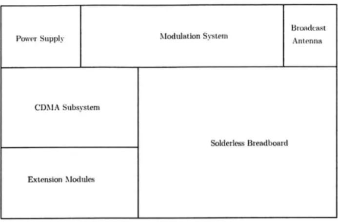
transmission-module diagram shown in Figure 2-3.
The independent power supply unit will allow the transmission module to work
indepen-dently from the reception module. The broadcast amplifier will be developed as part of the
first laboratory assignment in Section 3.1. The modulation system will also be developed
in the first assignment, described in Section 3.2. The CDMA subsystem will be discussed
in Chapter 6. A small section of solderless breadboard will also be included for rapid
pro-totyping. Lastly, power and signal interconnects will be included as part of an "extension
modules" section so that new functionality can be added to the lab kit in the future. The
Figure 2-3: Diagram describing the contents of the laboratory kit transmission module.
PCB circuit schematic of the transmission module design is included in Appendix B.1. The modules PCB layout is shown in Figure 2-4 with a larger version included in Appendix C.1.
All parts necessary for its construction are included in Appendix D.1.
_ 4.
U t. UU~ in
* j
.. ...- ...
Figure 2-4: Eagle CAD layout of the laboratory kit transmission module.
2.2
Reception Module
The reception module will be the basis for all the laboratory assignments signal recep-tion and demodularecep-tion components. This module will be more densely packed than the transmission module. The reception module will be made up of 8 separate sections: a power supply, the superheterodyne receiver, receiving antenna assembly, demodulator sec-tion, phase-locked loop secsec-tion, CDMA subsystem, solderless breadboard, and an extension modules section similar to the one included in the transmission module. These sections will be arranged as shown in Figure 2-5.
Like the transmission module, the reception module will have its own power supply Broadcast
Power Supply Modulation System Antenna
CDMA Subsystem
Solderless Breadboard
Extension Modules
Figure 2-5: Diagram describing the contents of the laboratory kit reception module.
allowing students to use it independently. The superheterodyne receiver will be the main reception component of the kit, its construction and design will be the subject of the second laboratory assignment, described in Chapter 4. The receiving antenna assembly will also be discussed in Chapter 4. The included demodulator circuits are the subject of several different laboratory assignments, each is tailored to a different communication method (e.g. AM, FM, CDMA, etc.). The two included phase-locked loop circuits will be part of design exercises in Chapter 5. The CDMA receiving subsystem is the subject of several exercises in Chapter 6. Solderless breadboard and extension interconnects are provided for prototyping and new functionality just like the transmission module. All of these functional areas are included in the reception module PCB whose schematic is in Appendix B.2. The modules PCB layout is shown in Figure 2-6 with a larger version included in Appendix C.2. All parts necessary for construction are in Appendix D.2.
Figure 2-6: Eagle CAD layout of the laboratory kit reception module.
Antenna Superheterodyne System Power Supply
CDMA Subsystem Demodulators
Solderless Breadboard
Chapter 3
Lab 1: Resonant Circuits,
Amplifiers, and AM/FM
Transmission
This chapter presents the first set of laboratory exercises to be taught in the wireless course. Students will design and construct the main transmission framework to be used through-out the semester, including circuits for amplitude and frequency modulation and a power amplifier for broadcasting signals. The block diagram for this framework is shown in Fig-ure 3-1. Students begin by working with passive energy storage elements, that is, inductors and capacitors. Combining these elements motivates the discussion of resonance and the theme of frequency-based analysis of signals and circuits.
Input X2001 Power
Modulating Amplifier Modulated Amplifier Broadcast
Signal I Signal IjSignal
Figure 3-1: Transmission-framework block diagram for the course laboratory kit.
Electromagnetic induction and resonance are key elements to the design of antennas for broadcast. Using resonance, circuits can be built around antennas that will select for and amplify certain frequencies. Frequency selection and amplification are key for creating the broadcast component of the framework. The broadcast antenna to be used will require
an amplifier to drive it. Students will use an RF linear amplifier designed to create large voltage swings at its output to increase the broadcast range.
After building the RF amplifier, students will broadcast their own signals from their circuits constructed on the laboratory kit. Two modulation schemes will be used for com-munication between the laboratory kit and a hand-held radio. First, amplitude modulation will be implemented using the XR2206 monolithic function generator. Then, this same process is repeated using frequency modulation which will also be implemented using the same XR2206 chip in a different configuration.
3.1
The Linear RF Power Amplifier Circuit
A large amount of power must be delivered to the laboratory kit transmission antenna
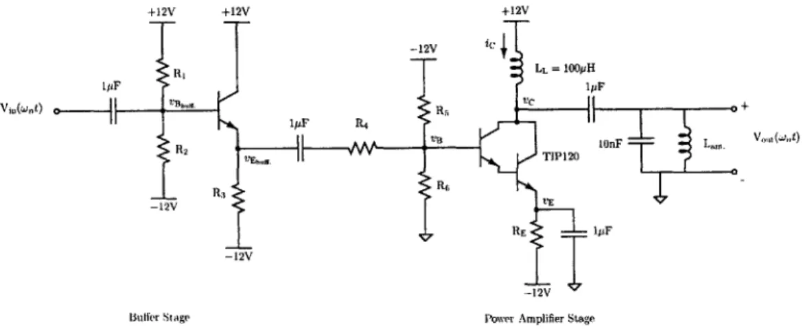
to achieve long broadcast distances. To do this, students will need to construct a power amplifier capable of driving an RF broadcast signal. The power amplifier will be of a linear design, creating an amplified replica of its input at its output. It will have two stages: a buffer and an RF power amplifier. The buffer stage will allow other devices with low output power characteristics to drive the RF power amplifier stage. The RF power stage itself will be responsible for creating a suitable high-power output for driving the broadcast antenna/LC tank. The overall amplifier, including both stages, is shown in Figure 3-2.
+12V +12V +12V -12V ic R , LL = 100pH 1piF 1PF in(WE) C T~ag.1pF R4 , ' + R2 VB TIP120) 100FLa -12V V - 12V 1pF -- 12V
Buffer Stage Power Amplifier Stage
3.1.1
Buffer Input Stage
The first stage in the overall amplifier circuit of Figure 3-2 is a buffer that uses a 2N3904
NPN bipolar transistor. The buffer circuit is an emitter-follower, unity-gain amplifier. It
will be used to ensure that circuits generating signals to be broadcast can drive the input of the power amplifier stage.
Students will begin their design of the buffer circuit by choosing an emitter resistor value that will create a desired emitter current of 9mA. The voltage across the emitter resistor, R3, is
VR3 = IER3 =
(9
x 10- 3)
R3Rearranging this equation and substituting for the potential difference across the resistor,
IE= 9 X 0-3 _- VEbuff. -- 12V VEbuff + 12V
R3 R3 R3
The voltage at the transistors emitter will be 0.7 V below the voltage at its base according to the 2N3904s specified base-emitter voltage drop [1]. Therefore, the emitter-current formula becomes
= 9 X 10-3 = - 0.7V + 12V R3
Assuming a negligible base current, the voltage at the base will be entirely determined by the biasing network shown in Figure 3-2. The base voltage is therefore
VBbuff bf. = R1
+
RR2 2(12V
--12V)
= R2 (24V)R,
+
R2Using two 12kQ resistors for R1 and R2, the current through the bias network is
24 _ 24
Ibias = 2 = 1mA
R,1+R2 24kQ
which is much greater than the base current 9mA
iB = ~A 90pA
for a conservative estimate of 100 for the current gain /. Thus, this base-current calculation verifies the previous assumption of negligible base current affecting the bias voltage.
Moreover, the base voltage should be set mid-way between the collector-emitter voltage. With this bias point, the buffer output signal can swing (at maximum) symmetrically about
its supply rails. Thus, to set VBbuff. to 0 V (half-way between +12V and -12V), the bias
network resistors must be equal. For a base voltage of 0 V, the emitter-current formula becomes
IE= 9 X 10- =-0.7 + 12V _ 11.3
R3 R3
Solving the formula for the necessary emitter resistance, R3,
11.3
R3 = 9 X _ :: 1.2kQ
1 0-3
With the emitter resistor value now selected the buffer circuit design will be complete.
3.1.2 Power Amplifier Stage
The power amplifier stage will use two NPN bipolar junction transistors in a Darlington pair configuration. These two transistors are packaged together as a single component called the TIP120 [2]. In a Darlington pair, the two individual transistors create an overall circuit with
current gain equal to the product of the two single transistors gains [31. Thus, the TIP120
acts as a single NPN bipolar transistor with a much higher gain than a single transistor. This high-gain property is valuable for maximizing the power delivered to an attached load, which in this case is a broadcast antenna. Higher amounts of power provided to an antenna load will translate directly into longer broadcast ranges.
Students will analyze the TIP120 Darlington pair as if it were a monolithic NPN bipolar
transistor. The resistor network at the base of the TIP120 (consisting of resistors R5 and
Rs) will set the forward-active region bias point. In the case of the TIP120, it must be biased at -4 V to remain in its forward-active region (thus the ratio of bias resistors must be R = 1). The input signal to the TIP120 power amplifier will be coupled to the bias
point using a resistor, R4 to limit the input current from the previous stage and the 1pF
capacitor from Section 3.1.1 for AC coupling.
RE. A 1pF capacitor to ground will also be placed in parallel with RE. The resistor in
the parallel combination provides emitter degeneration for stability in the face of thermal runaway. Connecting RE to the -12V rail also increases the voltage swing of the output to 24 V peak-to-peak. However, this resistor also limits the gain of the amplifier. In order to counteract this gain limitation, the parallel capacitor will be used. The parallel capacitor will appear as a short to high frequencies, increasing the RF gain of the circuit while allowing the RE to remain for its emitter degeneration properties.
At the collector of the TIP120, a 100pH inductor will be placed. This inductor is large enough to provide an approximately constant current through the collector of the transistor.
Including this constant current from the inductor LL, IDC, the total collector current can
be modeled as:
iC = IDC
+ irf sin(ont)
The signal current irf sin(wot) will be provided by the input signal (intended for broadcast) at the base. Although this small-signal model of the collector current would be considered inappropriate given the large amplitudes of the signals in question, the LC tank circuit attached to the collector output provides a measure of linearization for any distortions (thus the small-signal model will continue to be used) [4]. The constant current provided
by the large inductor LL will be blocked by the 0.33pF capacitor at the collector. Thus, the
output voltage will be related only to the drain signal current irf sin(wt). The LC tank will be tuned to this signal frequency w,, operating at resonance to create a large-amplitude sinusoid.
Moreover, the amplitude of the signal voltage at the collector of the TIP120 will swing symmetrically about the supply voltage. This property of the power amplifier appears due to the need for volt-second balance across the collector inductor LL. In small-signal terms, the collector inductor appears as a DC short (it does not allow a steady-state voltage to appear across it) allowing the sinusoidal output voltage to swing evenly about the collector-emitter voltage [4]. This provides sufficient output power for driving the antenna inductor to provide a broadcast signal at distances reasonable for communications across a large room. An oscilloscope capture of the power amplifier in operation is shown in Figure 3-3.
Figure 3-3: Power amplifier stage operating near the maximum output voltage. The input signal (bottom trace) is a simple sinusoid of magnitude approximately 1V peak-to-peak. The output voltage is over 36V peak-to-peak.
drive the LC antenna circuit for ranged broadcasts. The amplifier requires input currents that are perhaps too great for the output stages of other circuits generating signals to be broadcast. As a result, the RF linear amplifier also includes a buffer stage prior to the power amplifier stage to allow low output current circuits to drive the TIP120-based power amplifier. The combination of these two stages creates a suitable transmission frontend circuit for all of the courses broadcasting needs.
3.2
The XR2206 As A Modulation Platform
The data signals intended to be broadcast in later laboratory assignments vary in frequency between 100 Hz and 20 kHz. In order to accommodate this broad range of potential fre-quencies for broadcast the XR2206 monolithic function generator will be used. The XR2206 will modulate a single carrier frequency using the data signals created in each laboratory assignment. Using a single carrier cuts down on complexity, and the XR2206 allows for a carrier frequency that is low enough that it can easily be manipulated using breadboard-based circuits if necessary. Moreover, the XR2206 can perform various different modulation schemes, making it a convenient teaching platform on modulation techniques.
3.2.1 Amplitude Modulation
The first modulation scheme students will explore is amplitude modulation. A data signal will be used to change the amplitude of a carrier signal that is in turn broadcast using the power amplifier/resonant tank circuit from Figure 3-2. The AM system will follow the
canonical DSB/WC (Dual Sideband With Carrier) configuration shown in Figure 3-4 [5]. An input modulating signal x(t) is multiplied by a carrier signal c(t). The resulting signal has a scaled version of c(t) added to it to create the complete broadcast signal y(t).
X(t)
d(t)
E1-Yt
A
c(t)
Figure 3-4: Block diagram of the canonical DSB/WC modulation system.
Furthermore, the modulating signal x(t) is a sinusoid of the form V cos(wmt), where V
is the amplitude of the signal, operating at some frequency Wi, known as the modulating
frequency. The carrier, c(t), is also a sinusoid but operates at a higher frequency we (the carrier frequency) and takes the form cos(wct). The modulating signal is multiplied by the carrier to create the intermediary signal d(t) resulting in
d(t) = x(t)c(t) = V cos(wmt) cos(wet)
As a last step, a scaled replica of the carrier signal is added to d(t) to create the final modulated signal y(t). The carrier is added to d(t) to create an offset in the amplitude of y(t). This property is useful for asynchronous demodulation of the signal at the receiver, as discussed in Chapter 4 and in [5]. The final modulated signal to be broadcast is
y(t) = d(t) + Ac(t) = V cos(wmt) cos(wct) + A cos(wct) = (V cos(wmt) + A) cos(wct)
Factoring out the component A, gives the following formulation of y(t):
V
y(t) = A(1 + m cos(wot)) cos(wet) m =
-A
The factor m in this formulation is known as the modulation index or modulation depth. It is the maximum fraction of the carrier signal amplitude that is modulated [5]. That is,
amplitude. Students will be able to adjust this modulation index with the AM system they will build using the XR2206.
Therefore, to construct the AM system described above, the XR2206 will be used in its amplitude modulator configuration shown in Figure 3-5. The modulating signal x(t) will be AC coupled into pin 1 of the XR2206 using a 0.33 [F capacitor. The input pin also has
a DC bias placed on it by the resistor network consisting of R5, R6, and R7. The ratio of
the magnitude of the modulating signal to the DC bias at this pin will set the modulation index m. That is:
M
lvi
IVI
IVI(R 5 + R6 + R7)A R5+R,6+R7R+R 7 1 2 V 12(R6 + R7)
Moreover, the DC bias and thus the modulation index, can be adjusted using the
poten-tiometer R6. However, the user must be careful to not set the bias point to be half the supply
rail (in the case of Figure 3-5, 6 V). Doing so will set the XR2006 for a suppressed-carrier mode of operation which will not be covered in this lab exercise.
+12V R5 0.33 pF X(t) oR6 R-1 +12V AMSI SYMA2
R1 y(t) STO SYMA1
MO WAVEA2 C2 R2 C V- WAVEA1 C TCl GND TC2 SYNCO TRl BIAS R3 TR2 FSKI XR2206 R14 +12V FiT_ 0.33pF
Figure 3-5: XR2206 circuit configured as an amplitude modulator.
In the circuit of Figure 3-5, the carrier frequency can be set by adjusting the
pin (pin 11, SYNCO, which provides a square wave at the carrier frequency for reference
purposes). Three other potentiometers: Rsym, Rwav, and Rm will be used to adjust the
shape of the output signal y(t). Rsym adjusts the symmetry of the output waveform. Rwav
adjusts the shape of the waveform; how much it looks like a sinusoid. Finally, R, adjusts
the magnitude of the output waveform.
An example oscilloscope capture of the XR2206 working as an amplitude modulator is
shown in Figure 3-6. The modulating signal (top trace) is given a DC bias (middle trace) to
set the modulation index m. This signal in turn modulates the amplitude of the broadcast
signal (the bottom trace).
Tek t- l Pos:
000s5
MEASURE-H1 2.0J0 My 2510
us
C 1
-1r0Figure 3-6: Oscilloscope trace of the XR2206 acting as an amplitude modulator with m ~
0.25. The top trace is the modulating signal. The middle trace is the modulating signal with
DC offset to create a modulation index of 0.25. The bottom trace is the final modulated
carrier signal.
Using the XR2206 as an amplitude modulator will therefore create a circuit replica of
the canonical AM system from Figure 3-4. With this circuit, students will be able to explore
the properties of amplitude modulation systems including: adjusting the carrier frequency,
the modulating signal, and changing the modulation index.
3.2.2
Frequency Modulation
The second and last modulation scheme students will explore is frequency modulation. In
contrast to the AM system from Section 3.2.1, the modulating signal in a canonical FM
system changes the frequency of the carrier. This frequency-modulated carrier signal is
then broadcast using the power amplifier/resonant tank circuit of Figure 3-2. Unlike AM systems, FM systems are highly non-linear as the modulating signal x(t) now changes the
frequency of a broadcast signal y(t) [5). [5] describes FM system operation by expressing
a carrier signal c(t) in the form:
c(t) = A cos(wet + 0,(t)) = A cos(9(t))
In this equation, w, is the carrier frequency and 0,(t) is the phase of the carrier. The overall angle of c(t), 9(t), can be modulated by a function x(t). For example, the phase of c(t),
Oe(t) = Oo + kpx(t)
consists of 0, a constant, and x(t), a scaled version of the modulating signal. This in turn results in a modulation of the overall angle 9(t) of the carrier signal. Moreover, if x(t) is used to modulate the derivative of 9(t) then:
dO(t) = , + kfx(t)
d t
which would allow the modulating signal to change the frequency of c(t). Therefore, if the broadcast signal y(t) were related to the carrier signal c(t) by:
y(t) = c(t) = Acos(0(t)) = Acos dt dt)
then x(t) modulates y(t) as follows
y(t) = A cos
(J
wcdt +f
kfx(t)dt) = A cos (wet +J
kfx(t)dt)If x(t) = V cos(wmt), then
kf V
The instantaneous frequency of y(t) will then be
dO(t) =w, + kf X(t) = w, + kf V cos(wmt)
dt
which will vary sinusoidally between the values of w, - kf V and w, +
kfV,
making the totalchange in frequency,
w =w, + kfV -(w- kf V) = kfV
Rewriting y(t) to include the total change in frequency leaves
y(t) = A cos(wet + - sin(wmt))
WM
The factor " is known as the modulation index m for FM systems. Similar to the modu-lation index in AM systems, it is related to the portion of the total frequency that changes with x(t). The case where m is small is known as narrow-band FM. For a narrow-band signal,
y(t) = cos(wet + m sin(wmt)) = cos(wet) cos(m sin(wmt)) - sin(wet) sin(m sin(wmt))
Ir
~ cos(wct) - m sin(wmt) sin(wet) for m <
-2
With this approximation, the spectrum of y(t) is reduced to a small band near the carrier as shown in Figure 3-7. The band is related to the modulation index m. Students will be able to, as with the previous AM system, adjust this index in-circuit with the hardware FM system.
Therefore, to construct the FM system described above, the XR2206 will be reconfigured to act as a frequency modulator. Figure 3-8 shows the circuit to be constructed by students. The modulating voltage signal x(t) is placed at the timing resistor pin TR1 (pin 7) of the XR2206. This is the same pin responsible for setting the carrier signal frequency. This allows the magnitude of x(t) to directly modulate the carrier frequency. The carrier frequency can be grossly adjusted (setting the centered frequency w, from Figure 3-7) using
the potentiometer R5.
fre-13 (y(t))
mrt
7r fr WC W -M7rFigure 3-7: Approximate spectrum plot for a narrow-band FM signal from [5]
+12V R1 y) --+12V X(t) 3a R4 - R R5 R +12V 0.33pF
Figure 3-8: XR2206 circuit configured as a frequency modulator.
quency. The relationship between the modulating signal and the carrier determines the modulation index m. The XR2206 datasheet describes this relationship by the equation:
1 +VC
(R4
+
R5)C1(i+
R3 (I (i3 ))
Hz
The variable V, represents the modulating signal x(t) [6]. Substituting the modulating
signal into the above equation results in
fi
rt1+
ti e xi1(R4 +
R5)C1(
R33
With this equation relating the frequency
f
to x(t), the maximum deviation in frequencyAMSI SYMA2 STO SYMAL MO WAVEA2 V,. WAVEA1 TCl GND TC2 SYNCO TRI BIAS TR2 FSKI XR2206
Aw can be computed as follows:
zAw
= 27r(fmax - fmin) wherefmax
=f
2
Imaximum
Vcand fminf
minimum VWith the maximum deviation, the modulation index can be calculated using the formula:
Wm
Thus the modulation index is dependent on both the magnitude (through Aw as described
above) and the frequency of the modulating signal. Both of these parameters are adjustable
by the students, allowing them to explore several modes of FM operation.
In addition to being able to adjust the carrier frequency and modulation index, the
same carrier signal properties from the AM system in Section 3.2.1 can be adjusted using
potentiometers Rwav (for the shape of the waveform),
Rsym(for symmetry) and Rm for the
magnitude.
Oscilloscope captures of the frequency modulator circuit in operation are shown in
Fig-ure 3-9. The modulating signal, displayed as the top trace on both of the captFig-ures in
Figure 3-9 directly affects the frequency of the carrier signal (the bottom trace) as its
mag-nitude increases and decreases. This effect on the carrier is easier to see in Figure 3-9(a),
however the exact frequency of the modulating signal is more clearly visible in Figure 3-9(b).
(a) Carrier signal (bottom trace) exhibiting frequency modulation at approximately 200 kHz The modulating signal (top trace) is at a much slower frequency of 1 kHz
(b) The modulating signal (top trace) and
the subsequent FM carrier (bottom trace). Frequency modulation is present, but difficult to see at the time division shown.
Figure 3-9: Oscilloscope captures of the XR2206 operating as a frequency modulator.
the narrow-band FM concepts described above as well as in [5]. Specifically, with the FM modulator circuit students can explore the properties of FM systems including: adjusting the carrier frequency, and how the modulating signal also affects this frequency over a small band around the carrier frequency.
Chapter 4
Lab 2: The Superheterodyne
Receiver, and Asynchronous AM
Demodulation
This second laboratory assignment will lead students in the construction of a reception system that will complement the transmission system from Chapter 3. A block diagram of the system is shown in Figure 4-1. The reception system will use a tunable LC tank circuit to act as a receiving antenna. A signal received by this antenna will then be processed
by a mixer circuit. The mixer circuit will "mix down" the received signal frequency to an
intermediate frequency of 455 kHz in addition to providing some amplification. Lastly, the mixed down signal will be amplified by two IF amplifiers. Once amplified, the signal will be processed by any of the on-board demodulation circuits or any other signal processing systems on the laboratory kit reception module. After constructing the superheterodyne reception system, students will test it by constructing an AM demodulator circuit to work in conjunction with a received AM signal from the kit transmission module. Students will add other demodulators and baseband circuits in later laboratories.
4.1
The Superheterodyne Receiver
In this first set of exercises students will construct the superheterodyne receiver. Students will start by building a receiver antenna circuit to complement the transmitter antenna
Mlixer
Antenna/LC IF Amplifier D dAr Demodulated Output
Local Oscillator
Figure 4-1: Block diagram of the superheterodyne receiver system to be constructed includ-ing asynchronous AM demodulator.
built in Chapter 3. Next, students will build the mixer circuit, a vital component in the operation of the superheterodyne that mixes signals down to the intermediate frequency. Lastly, students will build two identical IF (intermediate frequency) amplifiers to amplify the mixer output.
4.1.1
Receiving Circuit
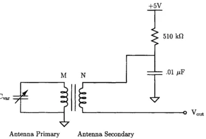
The first component to be constructed in the superheterodyne reception system is the receiving circuit. The receiving circuit will be responsible for picking up various signals radiated to the air for broadcast from the transmission system of Chapter 3. The circuit will consist of three components: a variable capacitor, a transformer (acting as an antenna), and a biasing network for the mixer circuit. The variable capacitor and antenna will be pre-packaged, off the shelf components given to students. The output of the antenna circuit will be connected to the next stage in the superheterodyne receiver, the mixer. A schematic of the intended circuit is shown in Figure 4-2.
The receiving circuit will operate by creating an LC tank circuit (like the transmission antenna from Chapter 3) with the transformer primary winding and the variable capacitor.
By changing the value of the variable capacitor, students will change the resonant frequency
of the LC tank, and thus select the frequency to be received. The secondary side of the
transformer will scale the amplitude of the received signal by the transformation ratio (
in the case of Figure 4-2).
Using a transformer will allow for the easy addition of a bias network to the secondary of the transformer/antenna. At DC, the capacitor in the bias network will look like an open circuit, creating a fixed bias current, set by the 510k Q bias resistor, at the output. This current will be the bias current for the base of the transistor in the mixer stage. For the AC signals of interest, the bias-network capacitor will act as a short to AC ground in parallel
+5V
510 kQ
M N - .01 pF
Cvar
Antenna Primary Antenna Secondary
Figure 4-2: Complete reception antenna circuit. The variable capacitor allows the antenna to be tuned to a wide variety of broadcast frequencies. The biasing network at the secondary allows the antenna output to appropriately drive the mixer stage.
with the resistor, making the secondary appear as an AC source. The output of the AC source will be the received signal coupled in from the primary winding.
4.1.2
Mixer
After the antenna, the next stage of the superheterodyne receiver system will be the mixer. The mixer will change the frequency of the antenna-received signal to the lower, intermediate frequency of 455 kHz. The mixer is the most vital component of the superheterodyne system.
By converting all incoming signals to the same frequency, the mixer allows all subsequent
amplifiers and processing circuitry to be designed to work at a single frequency. This feature greatly reduces system complexity. The mixer will always be able to mix the received signal down to 455 kHz by using a companion circuit called the local oscillator. The local oscillator will be tied to the same tuning system as the receiving antenna, allowing it to produce a signal approximately 455 kHz above the frequency to which the antenna is tuned.
Ideally, the mixer would operate by multiplying the signal r(t) from the receiving
an-tenna and the local oscillator signal l(t, set to be 455 kHz greater in frequency than r(t).
The multiplication of these two signals in time is the same as convolution in frequency. This convolution would create a signal that is exactly at 455 kHz as well as one at approximately
twice the frequency of r(t) as shown in Figure 4-3. The frequency components other than
3(r(t)) -fR fA 3(I(t)) - (fR + 455 kHz.) fR + 455 kHz. 4(Vmix(t)) -455kHz. 455 kHz - (2fR + 455 kHz.) 2fR + 455 kHz.
Figure 4-3: Frequency-domain convolution of the two mixer circuit inputs r(t) and
1(t),
theresulting signal Vmix(t) includes a component at the intermediate frequency of 455 kHz as
well as one at approximately twice the frequency of the received signal fR
However, the single-transistor mixer that will be used does not simply multiply the two signals. Instead, the mixer circuit shown in Figure 4-4 will exploit the nonlinearity of the
BJT to create an output that includes the resulting convolution of Figure 4-3 amongst
several other frequency components. The output current IC of the mixer is
IC = Ibe "TH
where VTH is the thermal voltage k. q The base-emitter voltage VBE is the difference between
the receiver and local-oscillator inputs r(t) and 1(t) with some DC bias VBE,
vBE = VBE + (r() - ())
Substituting the above equation into the output-current equation gives,
VBE +(r(t)-1(t))
Using the Taylor series expansion of the output-current, the term of interest is (from [4]),
9M
~(t)
2
VTH
A more detailed analysis of the mixer circuits operation can be found in [4], and [7].
In order to extract the output term of interest, a resonant element at the intermediate frequency will be used. This element will be a variable transformer component, the IF301, which includes a capacitor attached to the primary, creating a variable LC tank circuit. This transformer will be attached to the collector of the 2N3904 transistor in Figure 4-4. Students will be able to vary the resonant frequency of this tank circuit in order to tune the mixer to the intermediate frequency. Specific details on the mixer circuit design can be found in [4]. +12_V IF301 Vmix(t) r~t) 02N3904 r(t) .01 pLF 1.6 kQ
Figure 4-4: Single-transistor mixer circuit to be used in the laboratory kit reception module. The signal 1(t) can be taken from the local oscillator circuit or a function generator.
Local Oscillator
The mixer circuit will rely heavily on the signal 1(t) being 455 kHz above the received signal r(t). In order to create this signal 1(t) with its particular frequency characteristics, students will construct the Hartley oscillator shown in Figure 4-5. The Hartley oscillator uses positive feedback to create an oscillating signal at a frequency set by an LC tank at the collector of its transistor, much like the mixer circuit. Because the oscillators output 1(t)
must be related to the received signal r(t), the capacitor used in the LC tank will be the mechanically coupled to the variable capacitor used in the receiving antenna in Section 4.1.1. Thus as the user tunes the receiving antenna, the local oscillator is also tuned to match. The transformer attached to the transformer is also adjustable, which will allow students to
make minor adjustments to the frequency of
1(t).
Further details on the Hartley oscillatorcan be found in [4]. +5V IF300 :> (t) 470 kQ 1nF .01 pF 2N39-5.6 kQ
Figure 4-5: Local oscillator circuit used to generate the signal
1(t)
for the mixer stage. AHartley oscillator will be used with both a variable capacitor and transformer.
4.1.3
IF Amplifiers
The last stage in the superheterodyne receiver provides amplification. Two identical ampli-fier circuits will be used, both tuned (like the mixer stage) to the intermediate frequency. Each circuit will use 3 NPN bipolar transistors configured in a collector,
common-base cascade (see [4] and [7]). At the collector of the output transistor, an adjustable
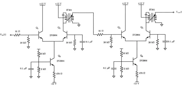
transformer like the one used for the mixer stage will be used by students to tune each am-plifier. The complete, dual-amplifier circuit is shown in Figure 4-6 with additional details on the operation of the differential amplifier available in [4]. An oscilloscope capture of the IF amplifiers working to amplify a received signal is shown in Figure 4-7
These last two amplifiers provided much-needed gain at moderate to long reception distances. Typically, a signal of 200 to 500 mV peak-to-peak maximum amplitude will be available as output from the mixer stage. In order for the mixed-down received signal to
+12_V +12_V +12_V +12_V IF301 IF301 Q1 Q2Q4 Q5 91 Q 91 Q Vi.(t) d 2N3904 2N3904 30 kOl 30 kQ 0.1 1F 30 k( 30 kf 0.1 F 6 kQ 16 kW 0.1 pF 3 kQ N30 0.1 AF .3 kf? 2 30 -12 V 470f -12 V47Q
Figure 4-6: Intermediate-frequency amplifier stage, consisting of two differential amplifiers tuned (using the IF301 variable transformer) to 455 kHz
Tak JL
0
sto M PO: -4t,000U1 P'intPRINT Butt Fl Folmat nwre -page 1 of 2 : ,i CH2 2-J,1V M .0M4s cH 2ZOV CH3 1OmV CH4 &UOV
Figure 4-7: Intermediate-frequency amplifiers working to amplify a received signal. The bottom trace is a 455 kHz signal received at the antenna. The next trace up is the same signal amplified by the mixer stage (still at 455 kHz since the received signal is at the intermediate frequency). The third trace is the output of the first IF amplifier, and the top-most trace is the output of the last IF amplifier.
be made appropriate for processing by other demodulator circuits in the laboratory kit its amplitude must be approximately 5 V peak-to-peak. The two intermediate amplifiers will provide the needed gain of at least 20 to the mixer output to obtain the desired signal levels. Moreover, it will also be desirable to maintain a constant 5 V peak-to-peak output no matter the magnitude of the mixer output. With a constant output, the superheterodyne
receiver becomes more reliable and better able to provide consistently valid output signals for the other on-board demodulator circuits. In order to accomplish this, the gain of the intermediate amplifiers will have to be adjusted automatically as the strength of the received signal changes. A circuit for AGC (Automatic Gain Control) is recommended for this
purpose by the ARRL (American Radio Relay League) in [8].
4.2
AM Demodulator
After constructing their superheterodyne reception system, students will use it to pick up a DSB/WC signal broadcast from the laboratory kit transmission module. Thus, prior to testing their receiver, students will construct an appropriate demodulator for the DSB/WC signal. The demodulator will consist of three components: a diode, a resistor, and a capac-itor as shown in Figure 4-8. This demodulator is asynchronous, it does not require use of a copy of the carrier (without modulation) to function.
1N4148
R C t
Figure 4-8: Asynchronous AM demodulator circuit. The diode acts as a half-wave rectifier followed by a parallel RC low-pass filter. The circuit output follows the envelope of its input signal.
More specifically, because a constant offset will have been added to the received signal at the transmitter as discussed in Section 3.2.1, the diode can be used as an effective half-wave rectifier. The offset allows the diode used in the demodulator to continue to conduct even when the modulating signal is zero in magnitude; preventing distortion due to cutoff during demodulation. Thus, the diode will effectively pass the positive half of the input signal (above the time axis in Figure 4-8.
Next, in order to extract the envelope of the received signal from the 455 kHz signal, a resistor and capacitor will be placed in parallel after the diode rectifier. This parallel combination will form a low-pass filter. The low-pass filter must pass the slower envelope
of the received signal but not the carrier. The intended input signal y(t) is
y(t) = e(t) cos(wet)
with envelope function
e(t)
=
A(1 + m cos(wmt))
In order to follow the envelope, the filter output Vdm(t) needs to be faster than the envelope. This "speed" is expressed using the derivative; that is, the derivative of the filter output voltage must be greater than the derivative of the envelope. This constraint is expressed
by the inequality,
d d
-Vdm(t)
: -- e(t)
dt
dt
However, the derivative of the output voltage must be less than that of the total signal, or the carrier will pass as well. Thus,
d
d
-Vdm(t) < ~-(t)
dt
dt
Moreover, the filter output voltage is defined by two different equations, one for the capacitor discharge cycle and one for the charging cycle. Solving the derivative constraints for one equation will also solve the constraints for the other. Thus, the more simple discharge equation,
Vdm(t) = Ve-
r
=RC
will be used below to solve for the resistor and capacitor values. The factor V is a constant,
expressing the point at time t = 0 where the capacitor starts its discharge cycle.
The first constraint inequality will be simplified by first taking the derivative of the discharge equation,
d d V
(V-Substituting the derivative into the first constraint inequality,
-- e~ r> -(A(1 + m cos(wmt)))
T dt
Taking the derivative of the right-hand side (assuming the discharge factor V is approxi-mately constant over a charge period),
V
-t--- e r > -Amwm sin(w + mt)
Canceling the negative factor from both sides of the equation above leaves,
V _i
Ve , Amwm sin(w
+
mt)T
To simplify the constraint inequality further, the constant term V will be solved for as fol-lows. The capacitor discharges starting at the voltage V and approaches zero. The starting voltage is determined by the envelope function e(t), as shown in Figure 4-9; the discharge voltage is shown in bold. Starting from the envelope, the capacitor voltage discharges until the next peak in the envelope, approximately following the envelope voltage.
When taking the derivative above, V was assumed to be constant, and now it will be assumed to vary as e(t) varies. This seemingly contradictory set of assumptions is predicated on a third assumption that e(t) varies much more slowly than Vdm(t). Therefore, equating
V to the envelope e(t),
Ve -~ A(1 + m cos(wmt))
Multiplying both sides by the exponential factor,
V ~ A(1 + m
cos(wmt))e-Substituting this value for V into the constraint inequality,
A(1 + m cos(wmt)) > Amwm sin(wmt)
Shifting terms to either side of the inequality yields,
1
+
m Cos(Wmt)m sin(Wmt)
The right-hand side of the inequality can be approximated as the reciprocal of the modu-lation index:
1 + m cos(Wmt) 1
m sin(wmt) m
Therefore, the inequality becomes,
1
WM<
Dividing both sides by the modulating frequency Wm,
1
One last substitution for the time constant simplifies the inequality to (also found in [9]):
RC<
1
mwm
Using this constraint approximation, students can choose appropriate values for the demodulator resistor and capacitor based upon the modulating signal frequency and modu-lation constant. For example, a 1 kHz modulating signal with modumodu-lation index of 0.25 will require a time constant no larger than 4 ms. For a capacitor value of 0.1 AF, the constraint inequality requires a resistor smaller than 40 kQ.
4.2.1
Demodulating An Audio Signal
Lastly, to test the complete superheterodyne-demodulator system, students will demodulate an audio signal broadcast from the kit transmission module. The signal will be received and mixed-down using the superheterodyne receiver, and then demodulated using the asyn-chronous AM demodulator described above. To test the effectiveness of their reception

![Figure 3-7: Approximate spectrum plot for a narrow-band FM signal from [5]](https://thumb-eu.123doks.com/thumbv2/123doknet/14509353.529391/36.918.254.686.112.352/figure-approximate-spectrum-plot-narrow-band-fm-signal.webp)