Publisher’s version / Version de l'éditeur:
Vous avez des questions? Nous pouvons vous aider. Pour communiquer directement avec un auteur, consultez la première page de la revue dans laquelle son article a été publié afin de trouver ses coordonnées. Si vous n’arrivez pas à les repérer, communiquez avec nous à [email protected].
Questions? Contact the NRC Publications Archive team at
[email protected]. If you wish to email the authors directly, please see the first page of the publication for their contact information.
https://publications-cnrc.canada.ca/fra/droits
L’accès à ce site Web et l’utilisation de son contenu sont assujettis aux conditions présentées dans le site LISEZ CES CONDITIONS ATTENTIVEMENT AVANT D’UTILISER CE SITE WEB.
Technical Translation (National Research Council of Canada), 1947-06-10
READ THESE TERMS AND CONDITIONS CAREFULLY BEFORE USING THIS WEBSITE. https://nrc-publications.canada.ca/eng/copyright
NRC Publications Archive Record / Notice des Archives des publications du CNRC :
https://nrc-publications.canada.ca/eng/view/object/?id=48cc403e-b61b-4fba-ac31-1028156c84a4 https://publications-cnrc.canada.ca/fra/voir/objet/?id=48cc403e-b61b-4fba-ac31-1028156c84a4
NRC Publications Archive
Archives des publications du CNRC
For the publisher’s version, please access the DOI link below./ Pour consulter la version de l’éditeur, utilisez le lien DOI ci-dessous.
https://doi.org/10.4224/20331573
Access and use of this website and the material on it are subject to the Terms and Conditions set forth at
Flow measurement by light interference Zobel, Th.
Ref Se r Q21 ~ 2 t 4 no. TT-20 BLDG COPY NO.
45
DIVISION OF MECHANICAL ENGINEERING
! TECHNICAL TRANSLATION NO. TT
-
20F L O W
MEASUREMENT BY
LIGHT INTERFERENCE
( STROEMUNGSMESSUNG DURCH LICHTINTERFERENZ ) BY TH. ZOBEL
FEE 18 1954
OTTAWA 1 0 JUNE, 1947
TPIS REPORT h1p.Y PlQT f?? rr"7: lcf;:r D I ' ! !a':: 'I '
0:: 1~ r P . 7 ~ b v i ~ i . . % i - - T I
-
y,,.i , i;-..; ~ - ; . " . I \ : T !'.r - c i .' .
.
"1.; .,* . : ? a 8 .*'2
6
/Q&';~i/X
NATIONAL RESEARCH LABORATORIES Ottawa, Canada TECHNICAL TRANSLATION D i v i s i o n of Mechanical Engineering Pages
-
23 F i g ,-
35 Teeh, Trans, TT-20 Date-
1 0 June 1947 F f l e-
12-R4-22 T i t l e : Stroemungsmessung durch L f c h t f n t e r f e r e n s By : Tho Zobel, BrunswickReference: Hermann Goering A e r o n a u t i c a l Research I n s t i t u t e 1 February 1940
ZWB FB 1167
Subject: Flow Measurement by Light I n t e r f e r e n c e Submitted by: W,Fo Campbell T r a n s l a t e d by:
Head, D ,A, S i n c l a i r
Aerodynamics Laboratory Approved by: J o H o Parkfn
D i r e c t o r ABSTRACT
An o p t i c a l measuring technique f o r t h e h i g h speed wind t u n n e l of t h e LFA i s being developed f o r q u a n t i t a t i v e and q u a l i t a t i v e flow s t u d i e s , The o b j e c t i s t o determine t h e d e n s i t y on t e s t b o d i e s i n the a f r flow and i n t h e i r nef ghborhood by i n t e r f e r e n c e measurement,
The r e s u l t s s o f a r o b t a i n e d i n simple prelfmfnary experiments show t h a t i t i s p o s s i b l e , even with s m a l l Rey- n o l d s numbers, t o a s c e r t a i n the d e n s i t y f f e l d surrounding a flow body by o p t i c a l means, Simple, a n a l y t f c a l r e l a t i o n - s h i p s give t h e connection between d e n s i t y , p r e s s u r e , v e l s - c i t y and temperature,
I n a d d i t i o n i n t e r f e r e n c e measurement f u r n i s h e s v a l u a b l e i n f o r m a t i o n about boundary l a y e r r e l a t i o n s h i p s , such a s t h e type (whether laminar o r t u r b u l e n t ) and t h i c k 0 n e s s , a s w e l l a s d i s t r i b u t f o n of temperature and v e l o c i t y ,
Page (if)
Tech, Trans, TT-20
TABLE
OF
CONTENTS --Pages
I Intkoduc tion 1
I1 The Interference-Sehlferen Apparatus at the Hermann Goerfng Aeronautical
Research Institute, Brunswiek 1
I11 Interference Measurements 5
IV
Boundary :Layer Invest igationaV
Analytioql Relationship between Den- sity, Pressure, Velocity and Temper-ature
13
VI Further Possible Applications of the
Interference Technique 15
Page
-
1Tech, Trans, TT-20
I INTRODUCTION
The development of -an o p t i c a l measuring technique f o r t e s t s i n t h e h i g h speea wind t u n n e l a t t h e Hernaann
Goering Aeronautical Research I n s t i t u t e , Brunswick ( f i g , 1) f s based on t h e fundamental i d e a t h a t t h e i n t r o d u c t i o n of any mechanical measuring instruments whatsoever i n t o a h i g h speed flow must be. avoided i f the ahu is t o g e t measurement d a t a not a f f e c t e d by d i s t u r b a n c e s , The extremely high pro- p a g a t i o n speed of l i g h t f u r t h e r recommended i t f o r use a s a measuring agency, s i n c e f n t h f s way even the most r a p i d phenomena i n a flow c m be r e g i s t e r e d completely f r e e from i n e r t i a ,
The choice f e l l upon a n i n t e r f e r e n c e procedure with s p a t i a l s e p a r a t i o n of t h e i n t s r f e r e n c e beams i n accor- dance w i t h t h e Mach-Zehnder p r i n c i p l e f o r a n a l y s i n g t h e d e n s i t y f f e l d surrounding a body s u b j e c t e d t o a flow, and
also
f o r a s c e r t a i n i n g t h e d i s t r i b u t i o n of p r e s s u r e on the? t e a t o b j e o t i t s e l f ,An o p t i c a l s c h l i e r e n method i s coordinated w i t h t h e measuring procedure s o t h a t t h e flow phenomena may be made v i s i b l e a t t h e same time,
I1 THE INTERFERE37 CE-SCHLEREN APPARATUS AT THE IXERMANEJ GOERING UROMAUTICAL
RESEARCH
INSTITUTE, BRUNSWICKThe p h y s i c a l p r i n c i p l e s of t h e i n t e r f e r e n c f pro- cedure have a l r e a d y been d e s c r i b e d elsewhere 1 to
,
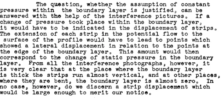
The b a s i c p l a n shown i n Figure 2 w i l l serve t o c l a r i f y the o p t i c a l measuring equipment d e s c r i b e d below,The l i g h t from a source L reaches the s c r e e n B v i a two d i f f e r e n t p a t h s of equal l e n g t h , The two p l a n e p a r a l l e l g l a s s p l a t e s P i and P2 a r e coated by e v a p o r a t i o n with a t h i n l a y e r of metal making them semi-transparent, The plane
m i r r o r s S1 and S2 a r e f u l l y r e f l e c t i v e , The l i g h t r e a c h i n g p l a t e PI i s thus d i v i d e d i n t o two e q u a l l y b r i g h t p a r t s , of which one i s r e f l e c t e d and t h e o t h e r allowed t o p a s s through t h e p l a t e ,
From p l a t e P1, both p a r t i a l l i g h t beams r e a c h p l a t e P2 v i a S1 and S2 and can then be brought i n t o i n t e r - f erence,
A p r e r e q u i s i t e f o r b r i n g i n g about t h e i n t e r f e r e n c e i s a c a r e f u l b a s i c adjustment of t h e apparatus i n which
a l l
p l a t e s and m i r r o r s must be p a r a l l e l and t h e two l i g h t ' p a t h s e x a c t l y equal, The beams t h e n i n t e r f e r e a t i n f i n i t y ,
Page
-
2Techo Trans, TT-20
I n
order t o b r i n g them i n t o i n t e r f e r e n c e on a pre- determined plane a n adjustment of t h e angles a t P1 and P2 must be made so t h a t t h e two p a r t i a l beams merge a t the image plane B ( f i g ,a*),
We then g e t a s t r i p system i n t h i s plane, which, by s u i t a b l e adjustment of the mirrors, can be a l t e r e d a t w i l l a s t o d i r e c t i o n and width of the s t r i p s ,If a t e s t medium of d i f f e r e n t d e n s i t y from the surrounding a i r i s placed i n the p a t h of one of the two p a r t i a l beams, c a l l e d the t e s t beam+ a d i s t o r t i o n of t h e i n t e r f e r e n c e s t r i p s occurs, The s i z e of t h e bulge i n a s t r i p i s a d i r e c t measure of t h e d e n s i t y i n t h e t e s t medium,
The adjustment of the angles i n t h e i n t e r f e r e n c e r e f r a c t o m e t e r determines the d i r e c t i o n of the s t r i p dis-, placement i n t h e i n t e r f e r e n c e image ( f i g , 3), This d i r e c - t i o n i s p o s i t i v e o r negative, depending on whether the two i n t e r f e r e n c e s t r i p s i n t e r s e c t t o the r i g h t o r l e f t of the s c r e e n ' s ( B ) c e n t r e p l a n e , To i l l u s t r a t e , f i g u r e 4 shows the s p a t i a l d e n s i t y f i e l d around a burning candle with the i n t e r f e r o m e t e r a d j u s t e d a t d i f f e r e n t angles,
By choosing t h e width of s t r i p the s e n s i t i v i t y of t h e i n t e r f e r e n c e procedure can be v a r i e d a s d e s i r e d
w i t h i n wide l i m i t s , By choosing the p o s i t i o n of the s t r i p s an8 the s i g n of the bulging, t h e procedure can be favour- a b l y adapted t o t h e p a p t i c u l a r t e s t case,
If we a r e d e a l i n g , as i n the f i e l d of aerodynamics, with t h e s t u d y of bodies w i t h i n a flow, t h e n by choosing our width of s t r i p we can a s c e r t a i n t h e d i s t r i b u t i o n of p r e s s u r e on the t e s t o b j e c t a t a g r e a t many measuring p o i n t s without the n e c e s s i t y of having p r e s s u r e h o l e s on t h e o b j e c t i t s e l f ,
Moreover, t h e d e n s i t y f i e l d a s a s c e r t a i n e d by i n - t e r f e r e n c e y i e l d s d a t a concerning t h e p o t e n t i a l flow near the t e s t o b j e c t a s w e l l a s valuable conclusions about boundary l a y e r phenomena,
The s c h l i e r e n procedure ( f i g , 2) i s used f o r a simultaneous q u a l i t a t i v e o b s e r v a t i o n of the flow phenomena, The l i g h t , of d i f f e r e n t wave l e n g t h s , i s brought from a source
Lg
v i a a semi-transparent plane p a r a l l e l p l a t eP @
t o t h e t e s t beam of the i n t e r f e r e n c e system, It proceeds with t h i s beam simultaneously and i n the same d i r e c t i o n through the t e s t medium, T h e r e a f t e r t h e s c h l i e r e n beam i s s e p a r a t e d from the i n t e r f e r e n c e beam by t h e second semi- t r a n s p a r e n t p l a t e ,P@s,
and l i k e w i s e reaches the s c r e e n B over t h e s c h l i e r e n s t o p , The r e s u l t is a s c h l i e r e n image of the flow phenomena of t h e same s c a l e a s the i n t e r f e r e n c e image,Page
--
3Tech, Trans, TT-20 F i g u r e 5 shows diagrammatically t h e l i g h t p a t h of t h e i n t e r f e r e n c e - s c h l i e r e n a p p a r a t u s designed a t t h e Hernrann Goering Aeronautical Research I n s t L t u t e o The l i g h t L, fPom a n u l t r a - h i g h p r e s s u r e mercury lamp (upper l e f t ) of h i g h e s t p o s s i b l e i n t e n s i t y i s r e f l e c t e d a t a small m i r r o r , l o , onto t h e concave m i r r o r , 2, It proceeds from t h e r e a s a p a r a l l e l beam t o t h e guide m i r r o r , 3, and t h e n t r a v e r s e s t h e four- p l a t e system a s shown i n f i g w e 2, A f t e r t h e two p a r t i a l
i n t e r f e r e n c e beams have come t o g e t h e r a g a i n a t p l a t e
P2,
t h e l i g h t p a t h continues v i a guide m i r r o r s , 4 and 5, t o
r e a c h t h e concave m i r r o r , 6, This m f r r o r , which has a l a r g e f o c a l l e n g t h (f
=
3,5m), produces v i a m i r r o r s 7, 8 and 9 a n image of t h e t e s t o b j e c t i n t h e wind t u n n e l , Mirror 9 i s semi-transparent s o t h a t t h e l i g h t beam reachingi t
i s d i v i d e d i n t o two p a r t s , The s t r o n g e r p a r t i s used f o r t h e image t o be photographed; t h e weaker p a r t i s conducted v i a m i r r o r 1 0 t o a ground g l a s s p l a t e f o r o b s e r v a t i o n , A colour f i l t e r i n s t a l l e d i n t h e l i g h t p a t h s e r v e s t o e x t r a c t t h e wave l e n g t h sh l =
5770/90A o U o D
which a r e e s p e c i a l l y s u i t e dt o our purposes,
The change i n the o p t i c a l p a t h of t h e t e s t beam, caused by t h e r e f r a c t i v e index of t h e windows i n t h e wind t u n n e l .and of t h e end p l a t e s of the model, i s e q u a l i z e d by a coxpensator i n t h e p a t h of t h e second beam,
The l i g h t p a t h of t h e s c h l i e r e n system begins a t t h e source
LO
(lower l e f t ) and proceeds v i a m i r r o r s 11 and 12 t o t h e concave mirror, 13, From t h e r e t h e p a r a l l e l beam reaches the t e s t beam of t h e - i n t e ~ f erometer v f a t h e semi-transparent p l a t e , 14, Together w i t h t h i s beam L t passe$ through t h e a i r flow v i a t h e windows i n the w a l l of t h e tunnel and t h e end p l a t e s of tfie t e s t model ( c f , f i g , 21,P l a t e 1 5 a g a i n s e p a r a t e s t h e s c h l f e r e n beam and d i r e c t s i t v i a t h e guide mirr,or, 16, t o tfie' concave m i r r a r , 17. This, i n t u r n , forms an image of t h e t e s t model i n t h e plane of t h e image t o be photographed as w e l l a s t h a t of t h e ground-glass p l a t e , It has the same f o c a l l e n g t h and t h e same o b j e c t d i s t a n c e and hence t h e same s c a l e a s t h e i n t e r f e r e n c e p i c t u r e , -The p a t h i s over t h e s c h l i e r e n s t o p v i a m i r r o r s 18 and 19,
Thus the course of t h e experiment can be observed continuously through both optical.,systems on a s c r e e n con- t a i n e d i n a sound-proof compartment, while independently of t h i s t h e same s u c c e s s i o n of events can be photographed o r filmed, A high frequency motion p i c t u r e a p p a r a t u s per-
Page
-
4Tech, Trans, TT-20
mlts the filming of exceptionally interesting and rapfd
phenomena at high picture frequencies, while the light sources can be controlled from the motion pfcture camera to give brief, strong overloading (and thus an increase in light intensity),
For special tests of short-lived occurrences
a
flash installation is also provided for as an additional light source, This instal ation permits single photographs with exposure times of lom8 second (fig. 5 ) . Looking at the left-hand side of the diagram we can see that by simply changing the positions of mirrors 1 and 11 the spark fllu- mination can be introduced into the two previously descrfbed paths of the optical system, The optical arrangement shown
fn figure 5 was chosen so as to reduce the large path dfs- tances in the apparatus itself before photographfc repro- duction, and so that both photography and observation could be undertaken close to the test area,
All optical-me chanical components are housed in a large test carriage bui lt in the form of a box-girder, which can be insulated from the outside by heat-absorbing materials so as to shield the testing apparatus from sur- rounding temperature disturbances,
All mirrors and plates are mounted in universal arrangement, Each therefore is capable of angular rotation about two axes at right angles to each other, When the
apparatus has been adjusted most of the mountings are locked, The only components which remain movable while the apparatus
is in operatJon are plates PI and PZ of the Interferometer, the compensator, and the two plane parallel plates, 14 and 15, of the schlieren system,
The adjusting mechanisms of the mirrors, as well as the optical componentsl themselves, must be extremely precise, since angular adjustments as small as a fraction of a second must be possible,
The adjustable mirror units are fitted with mul- tiple worm gears for fine adjustment, The reduction ratio fs 1:73,000,000, The mfrrors can be worked by electrfcal remote control from the test compartment, by means of which the smallest possible angular adjustment 1s 1/10 second,
1,
All optical components were obtained from the firm of Halle and Sons, (~alle Nachf,), Berlin-Steglite, The excellent universal mountings for the mirrors of the interferometer were also manufactured by Halle & Sons in accordance with our specifications,& -; , . r , c ..- -I 3 Tech, T ~ a n s TT=28 A n e l e c t r i c a l i n d i c a t i d n of a n g u l a r adjustment i s l i n k e d
t o each d r i v e mechanism s o t h a t a n e x a c t p i c t u r e of t h e ad- justment of t h e measuring equipment i s always o b t a i n a b l e a t t h e c o n t r o l desk,
The t e s t c a r r i a g e i t s e l f r e s t s v f b r o t e c h n f a a l l y on suspended beams, f o e o , i t i s connected t o t h e . o u t e r mobile s u p p o r t i n g s c a f f o l d by a c c u r a t e l y c a l i b r a t e d r e s t o r i n g
s p r i n g s , I n t h i s way t h e t e s t a p p a r a t u s i s p r o t e c t e d from a l l nearby shocks, whether they come from the wind t u n n e l o r the b u i l d i n g ( f i g , 61,
INTERFERENCE MEASUREMENTS
While a t p r e s e n t t h e s c a f f o l d i n g i s s t i l l b e i n g designed, t h e i n t e r f e r e n c e p a r t of t h e t e s t i n g equipment h a s been i n o p e r a t i o n f o r about h a l f a y e a r w i t h a pro- v i s i o n a l c a r r i a g e of t h e o r i g i n a l s i z e , The f f r s t e x p e r i - ments have a l r e a d y been completed p e r t a i n i n g t o o p t i c a l
compensation and t o t h e a n g l e s e n s i t i v i t y of g l a s s p l a t e s i n t r o d u c e d i n t o t h e t e s t beam a s boundaries f o r the wind t u n n e l and t h e model, F u r t h e r , a small e x p e r i m e n t a l wind t u n n e l has been b u i l t s o t h a t flow measurements by means of l i g h t i n t e r f e r e n c e could a l r e a d y be c a r r i e d o u t ,
The b u l g i n g of t h e i n t e r f e r e n c e s t r i p s a s compared
w i t h t h e u n d i s t u r b e d s t r i p f i e l d ( w i t h o u t a i r f l o w ) , p r o v i d e s a d i r e c t measurement of t h e d e n s i t y , i n accordance with t h e equat i on
where
A y
(m)
=
t h e s t r i p bulge;b
(mu$ =
t h e d i s t a n c e between two u n d i s t u r b e d i n t e r f e r e n c e s t r i p s ;n,
-
P
=
r e f r a c t i v e index i n e u n d i s t r u b e d 2% medium=
0 , 0 0 0 2 9 3 ~-
T-
P ~ , Y ] =
a i r d e n s i t y i n u n d i s t u r b e d c o n d i t i o n :>(mm)
=
wave l e n g t h of l f g h t employed (5798A,U,];
L(mrn) = l e n g t h of l f g h t p a t h w i t h i n t h e medium of a l t e r e d d e n s i t y ,
The magnitude
3-
2s independent cf the s c a l e ofb
Page
-
6Tech, Trans, TT-20
or
an a d i a b a t i c change o f ' c o n d i t i o n t h e arelation- s h i p between d e n s i t y and s t a t i c p r e s s u r e i n t h e flow f i e l d f a given by t h e equationIf the s t a t i c p r e s s u r e on the s u r f a c e of-the sub- merged body
i s
t o be a s c e r t a i n e d , t h e n p andP
a r e p r e s s u r e and d e n s i t y on t h e t e s t o b j e c t and p, andp ,
a r e t h e .p r e s s u r e and d e n s i t y i n t h e undisturbed flow, Thus fn t h e . ' f i r s t approxfmation we have - -
When t h e Mach number i s & r e a t e r t h a n 0.5, then,
w i t h
the e x a c t formula f o r t h e a d i a b a t i c processes we g e t. .
For the u s u a l p r e s s u r e c o e f f i c i e n t
9
i n measure- Qments of p r e s s u r e d i s t r i b u t i o n we thus g e t the f o l l o w i n g expression ( f o r
M
0,5):The value
P p ,
however, i s known from the o p t i c a l measurement, Hence - . - . Numerical Example For e v a l u a t i n g a d e n s i t y f i e l d SpanL
=: 170mm,
S t r i p width on photograph'b = 2,7mn, Dynamic p r e s s u r e i n the t e a t s e c t i o n q=
350 kg0ms2 p = 9975 kg.mo2 a t a temperature ofla0
C,page
-
7Tech, Trans, TT-20
Thus when the width of the s t r i p i s given the bulge needs only t o be m u l t i p l i e d by a c o n s t a n t f a c t o r f n order t o g e t t h e p r e s s u r e c o e f f i c i e n t ,
From the r e s u l t obtained f o r b y we see t h a t t h e technique must be extremely s e n s i t i v e t o the s m a l l e s t den- s i t y changes, s i n c e the s t r f p displacement measured i n t h e i n t e r f e r e n c e p i c t u r e i s d i r e c t l y p r o p o r t i o n a l t o the s t r f p width a s w e l l a s t o t h e l e n g t h L (on an a i r f o i l L f s t h e s p a n ) , I t s remarkable s e n s i t i v i t y r e s u l t s from t h e f a c t t h a t the d e n s i t y change a c c u r r i n g a t each p i n t f n the flow f i e l d i s i n t e g r a t e d over t h e e n t i r e e x t e n s i o n f n depth
(L)
of the t e s t medium, Through the choice of t h e s e two mag- n i t u d e s b and L t h e s e n s i t i v i t y of t h e measuring technfque
can be adapted wfthfn wide limits t o t h e experfmental eon- d i t i o n s i n any given i n s t a n c e ,
I n t h i s connection i t shoul$ be mentioned t h a t the theory of p o t e n t i a l flow t r e a t s the air a s an fncom-
p r e s s i b l e medium up t o a flow speed of BOO meters p e r s e w n d , f o e , , f t i s assumed t h a t t h e d e n s i t y remains c o n s t a n t w i t h i n t h i s range, The f a c t , however, t h a t f n r e a l f t y a change of d e n s i t y aceompanfes every change of speed, i s j u s t t h e p r f n c i p l e of measurement underlying t h e i n t e r f e r e n c e t e eh- nfque, The assumption t h a t t h e d e n s i t y i n the p o t e n t f a l flow f s c o n s t a n t f o r a l l - p l a n e sac.tfons i n the flow f f e l d
f a an e r r o r of n e g l i g e a b l e p r o p o r t i o n s , Howevep, .the i n - t e g r a l value of t h e s e small magnitudes, c a l c u l a t e d over t h e l e n g t h L, r e s u l t s I n s u f f i c i e n t dfsplacement of the i n t e r -
f erence s t r i p s f o r measuring purposes,
I n the e a r l y s t a g e s of development of t h i s optf c a l technique i t was supposed t h a t I n any case a f a r - r e a c h i n g Improvement i n the s e n s i t i v i t y of the method would ha've t o be sought, The r e s u l t s s o f a r obtained, however, a l r e a d y show t h a t even on a s m a l l model (170 mm, s p a n ) , and a t normal flow speed, a a t l s i a e t o r y s t r i p displacements a r e obtained, A s a consequence t h e natuzze
of
the problemhas
Page
--
8Tech, Trans, TT-20
One h a s o n l y t o c o n s i d e r t h a t t h e s i z e of t h e s t r i p bulge i s p r o p o r t i o n a l n o t o n l y t o b and
L,
but a l s o t o t h e change i n d e n s i t yAP
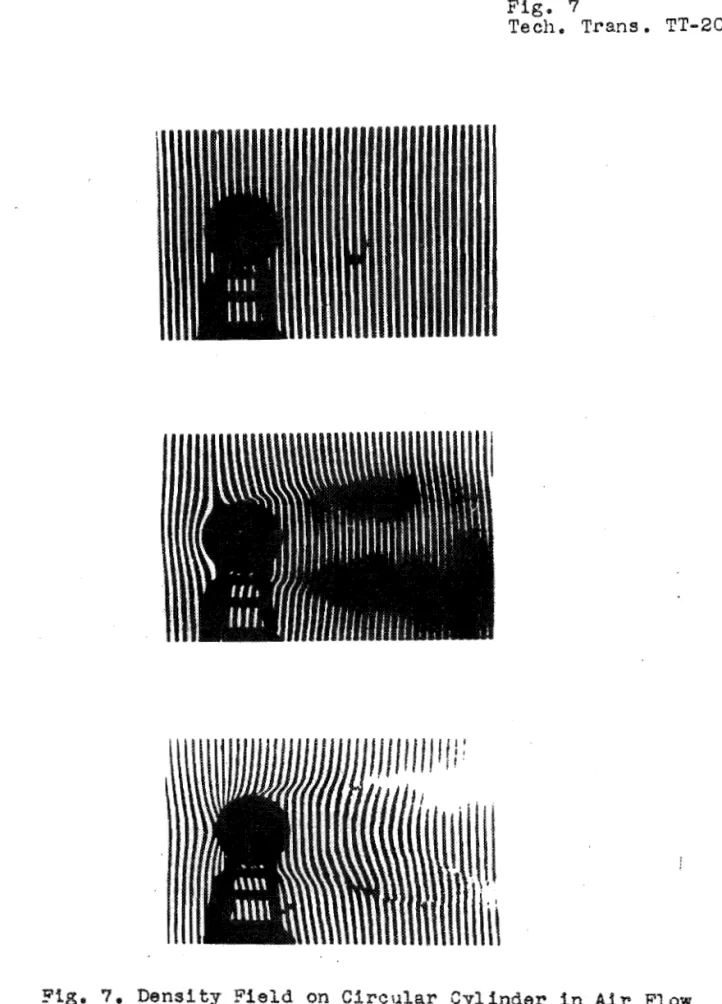
and consequently a l s o t o t h e square of t h e speed, o r , i n a compressible flow, approxf- mately t o t h e speed i t s e l f , t o r e a l i z e t h a t l a r g e s t r f p d i s p l a c e m e n t s must occur when t e s t s a r e made i n t h e h i g h speed t u n n e l , I f t h e span width, a s used i n t h e s e p r e l f m f - n a r y experiments, i s m u l t i p l i e d by 1 0 and t h e speed of f l o w by 4, t h e n w i t h t h e s t r i p w i d t h t h a t h a s been t h u s f a r em- ployed we can e x p e c t a s t r i p displacement about f o r t y times; a s g r e a t , It w i l l t h e r e f o r e be n e c e s s a r y a t times, when u s i n g t h e g r e a t e s t p o s s i b l e speed of f l o w i n t h e h i g h speed wind t u n n e l , t o reduce b o t h t h e span width of the model and t h e width of s t r i p I n t h e i n t e r f e r e n c e p f c t u r e c o n s f d e r a b l y , No d i s a d v a n t a g e r e s u l t s , aerodynamfeally, from u s i n g end p l a t e s a t t h e e x t r e m f t f e s of t h e model (two-dfmensioml pro- blem). The c h o i c e of t h e v e r y narrow f n t e r f e r e n c e s t l i p s only i n c r e a s e s t h e number of measurfng p o f n t s on t h e t e s t o b j e c t , For e v a l u a t f on purposes, t h e r e f o r e , we can s e l e c t . a t w f l l whatever measuring p o f n t s a r e c o n s i d e r e d i m p o r t a n t ,Ffgure 7 shows t h e d e n s i t y f i e l d of a c y l i n d e r of l e n g t h L = 170
nun,
and dfameter D=
25 mm,, a t a f l o wv e l o c f t y of 75 m e t r e s p e r s e c , , and w i t h both s i g n s of t h e s t r f p displacement a s determined by t h e adjustment of t h e a n g l e s i n t h e I n t e r f e r o m e t e r , It f s very e l e a r , i n t h e example gfven, t h a t t h e d i r e c t i o n of t h e s t r f p b u l g e s a s shown i n F i g u r e 7a f s t h e b e t t e r f o r e v a l u a t i o n purposes, s i n c e t h e r e a r e a g r e a t many more measurfng p o f n t s t o be
had n e a r the s t a g n a t i o n p o i n t and I n t h e acce-leratfon r e g i o n , Note t h e pronounced t r a n s i t f o n i n t h e d e n s i t f e s from poten-
t f a l flow t o t h e s t a g n a t f o n r e g i o n , a s w e l l a s t h e unffo$m i n t e r m e d i a t e v a l u e of t h e densi-ty behind t h e r e s i s t a n c e body, Also t o be noted i s the way f n which a very i n t e n s e t r a n s f e r of e n e r g y t a k e s p l a c e in the two v o r t e x t r a i n s a t a d i s t a n c e of about one c y l i n d e r d f a m e t e r behind t h e t e s t body, This 1s caused by r a p f d changes i n v e l o c i t y , The h a z i n e s s I n the i n t e r f e r e n c e p f c t u r e r e s u l t s from t h e f a c t
t h a t t h e frequency of t h e d e n s i t y changes f a g r e a t e r t h a n t h a t c o r r e s p o n d i n g t o t h e exposure time used, v f z , 1/200 second, I n t h e continuous p f c t u r e of a slow motfon camera we would s e e how r a p i d l y t h e d e n s i t y v a r i a t i o n s occb.1.':
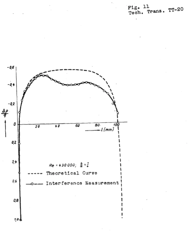
Ffgure 8 shows t h e d e n s i t y q i s t r i b u t i o n on t h e c y l i n d e r o v e r a range of a n g l e s from O0 t o b80°, a s p l o t t e d f r o p t h e I n t e r f e r e n c e measurement, F o r - purposes of comparf- s o n a d e n s i t y d i s t r i b u t i o n curve from & a n d
M,
1210 i sp l a c e d a l o n g s i d e , The comparison shows t h a t t h e optf c a l measuring technique i s r e l f a b l e and supplies a b s o l u t e v a l u e s even under t h e p r i m f t f v e c o n d i t f o n s s f t h e s m a l l e x p e r i m e n t a l
Page
-
9Tech, Trans, TT-20 t u n n e l , This t u n n e l h a s a s y e t no honeycomb and the v e l o c i t y d i s t r i b u t i o n i n t h e t e s t s e c t i o n i s v e r y poor, Apparently, too, i t has a very h i g h turbulence l e v e l ,
Figurns 9 and 1 0 show the d e n s i t y f i e l d around a n e l l i p t i c cylindb2 with an a x i s r a t i o of 4 ~ 1 a t two d i f f e r e n t angles of a t t a c k , O0 and 8' and with both s i g n s of the s t r i p displacement, Figures 11 and 12 show t h e r e s u l t s of the
i n t e r f e r e n c e measurement u s i n g both angles of a t t a c k and f o r comparison t h e r e s u l t of the p r e s s u r e d i s t r f b u t f o n as c a l c u l a t e d f o r z e r o incidence,
It i s worth n o t i n g t h a t the d e n s i t y d i s t r i b u t i o n on t h e e l l i p t i c c y l i n d e r depends t o a l a r g e e x t e n t on t h e ReynoldsP number and on t h e turbulence l e v e l of the wind
tunnel, a s t h e r e s u l t s of the measurements i n NACA Report No, 652 shorn, The curve of d e n s i t y d i s t r i b u t i o n from the i n t e r f e r e n c e measurement i s very s i m i l a r t o t h e r e s u l t an- nounced i n t h e MACA Report f o r a d f f f e r e n t a x i s r a t i o , Com- p l e t e agreement of the a b s o l u t e v a l u e s w i t h t h e measurements from o t h e r t u n n e l s and with the theory i s not t o be expected f o r .the reasons nentioned,
I n a d d i t i o n p r e l i m i n a r y experiments on a i r f o i l p r o f i l e s were made, Figure 13 shows a s e r i e s of a t t a c k a n g l e s of the p r o f i l e Goe, 387, from which d e n s i t y d i s t r i - b u t i o n f i g u r e s a r e d e r i v e d , Since the p r o f i l e i n q u e s t i o n has a t h f c h e s s , amounting t o PO p e r cent of t h e t u n n e l
diameter, the angular s e t t i n g r e s u l s s i n c o n s i d e r a b l e changes i n t h e flow f i e l d due t o crowding of t h e j e t , C a l c u l a t i o n s and comparisons can only be made, t h e r e f o r e , f o r
=
O0and, i n some c a s e s , U
=
5,7*, With o t h e r angles of a t t a c k t h e v e l o c i t y in the t e s t s e c t i o n can no l o n g e r be determfned, For s t u d y purposes t h e photographs a r e given w i t h t h e s i g nof bulge displacement t h a t i s the l e a s t favourable f o r e v a l u a t i o n , Note the d l s t o r t i o n of t h e s t r i p s around t h e l e a d i n g edge n e a r the s t a g n a t i o n p o i n t ,
Figupe 14 shows the r e s u l t of i n t e r f e r e n c e
measurement on t h e prof i&- Goe, 38'7 compared t o t h e Goett in- gen p r e s s u r e d i s t r i b u t i o n measurement f o r
a
=
Q O , The de-v i a t i o n i n the p r e s s u r e d i s t r i b u t i o n on the p r e s s u r e s i d e of t h e p r o f i l e f s caused by the d i s t u r b a n c e s due t o t h e support,
Figures15 and 16 show f o r the angle of a t t a c k
a
= 5,7@ the i n f l u e n c e of t h e support a s t h i si s
placed r e s p e c t i v e l y on the a u c t j o n s i d e and on the preeaure a i d e of t h e a i r f o i l , Figure19
i v e s t h e p r e s s u r e d i s t r i b u t i o n on the undisturbed p r o f i l ef
without s u p p o r t ] aa compared t o t h e Goettingen p r e s s u r e d i s t r i b u t i o n curve,Page
-
POTech, Trans, TT-20
I n t h i s experiment the d i s t u r b a n c e due t o t h e support i s very n o t i c e a b l e , because i n t h e f i r s t p l a c e t h e l a t t e r i s placed very c l o s e t o t h e w a l l of t h e t u n n e l , and secondly t h e span of t h e model i s very small, I n t h e h i g h speed t u n n e l t h e r e l a t i o n s h i p s a r e much more favourable, Moreover i t would be no problem t o i n s t a l l t h e model
in
such a way t h a t t h e supports would be o u t s i d e the end p l a t e s and t h u s e l i m i n a t e any i n f l u e n c e of the d i s t u r b a n c e on t h e flow a g a i n s t the a i r f o i l i t s e l f ,
Ffgures 1 8 and 19 show a s e r i e s of a n g l e s of a t t a c k w i t h -a Joukowski prof i l e of l O mm, chord up t o flow separa- t i o n ,
I n a l l t h e i n t e r f e r e n c e p f c t u r e s i t can be aeen t h a t the s t r i p s i n the s t a g n a t i o n r e g i o n d i r e c t l y behind a r e s i s t a n c e body, a s w e l l a s thase i n t h e flow beyond a t some d i s t a n c e from t h e model, show measurable bulgfnga from which t h e r e s i s t a n c e can be a s c e r t a i n e d , The e v a l u a t i o n procedure1 f o r determining the r e s i s t a n c e i s now being worked o u t ,
Up t o t h f s p o i n t f t has been t a c i t l y assumed t h a t t h e I n t e r f e r e n c e s t r i p s a r e produced by monochromatic l i g h t w i t h t h e e n t i r e image f i e l d made up of s a t u r a t e d i n t e r f e r e n c e s t r i p s , Homogeneous l i g h t was indeed used i n a l l the examples s o f a r shown, There a r e , however, i n s t a n c e s of a p p l i c a t i o n where i t i s n e c e s s a r y t o f d e n t i f y a f n g l e s t r i p s , For t h i s r e a s o n c e r t a i n ones must be a c c e n t u a t e d , This occur8 i n t h e s o - c a l l e d z e r o - i n t e r f e r e n c e , where s f n g l e s t r i p s of d i f - f e r e n t degrees of s a t u r a t i o n and d i s t i n c t n e s s appear,
If we use q l i g h t t h a t emits s e v e r a l wave l e n g t h s t h e s e w i l l give d f f f e r e n t f n t e r f e r e n c e s t r i p wfdths, The r e s u l t i s a group formation of s t r i p s , Between t h e f n d i v f - d u a l s t r f p groups, a t the p l a c e where t h e maximum i n t e n s i t y of one c o l o u r system c o i n c i d e s e x a c t l y w i t h the milnfmum in- t e n s i t y of another, t h e l i g h t 1s wholly e x t i n g u i s h e d and no I n t e r f e r e n c e t a k e s p l a c e , There 1s o n l y one s t r i p group contafnfng a h e a v i l y s a t u r a t e d s t r i p , the s o - c a l l e d zero- i n t e r f e r e n c e , which f s formed f n t h e l f n e of symmetry of a l l coherent p o i n t s of l i g h t , The presence of t h i s zero- i n t e r f e r e n c e i s a t t h e same time t h e c r i t e r i o n f o r complete adjustment of the i n t e r f e r o m e t e r , A t t h i s s t a g e t h e two l i g h t paths ( f i g , 2 and 3 ) must be s o n e a r l y e q u a l i n l e n g t h t h a t they d f f f e r o n l y by f r a c t i o n s of h a l f a wave l e n g t h of - t h e l i g h t e m p P o c - , -
.
1,
A s e p a r a t e r e p o r t i s being i s s u e d on t h e e v a l u a t f o n procedure i n f n t e r f e r e n c e measurement,Page
-
hl
Tech, Trans,
TT-2D
Figure 20 shows a p i c t u r e of z e r o - i n t e r f e r e n c e from a mercury vapour lamp, The z e r o - i n t e r f e r e n c e s t r i p i s c l e a r l y d i s t i n g u i s h a b l e from the o t h e r s by
i t s
heavy blackening,Figure 80 shows f u r t h e r , how advantageously t h e z e r o - i n t e r f e r e n c e
can
be used t o a s c e r t a i n , f o r example, t h e v e l o c f t y i n the closed wind t u n n e l , I f the upper p a r t of the photograph r e p r e s e n t s the i n t e r f e r e n c e s t r i p p i c t u r e with the known o r i g i n a l c o n d i t i o n of the wind t u n n e l wfth- out flow(v
=
O), t h e n the Power p a r t shows the d i s p l a c e d s t r i p f i e l d under flow, The e x t e n t of the dfsplacement i s d i r e c t l y p r o p o r t i o n a l t o t h e change i n d e n s i t y and there- f o r e t o the flow v e l o c i ty, S i m i l a r l y temperature and f l u f - d i t y s t r a t a and the l i k e , can be measured w i t h zero-intep- f e r e n c e , s i n c e these c h a r a c t e r i s t i e s of the otherwise homo- geneous t e s t medium a r e accompanf ed by d e n s i t y v a r i a t i ona,IV
BOUNDARY LAYER INVESTIGATIONSThe i n t e r f e r e n c e p i c t u r e s of the a i r f o i l s sub- jected t o flow a l r e a d y show o t h e r very i n t e r e s t i n g r e s u l t s which a l s o l e n d themselves t o the measurement of p r e s s u r e d i s t r i b u t i o n , The formation of t h e boundary l a y e r and i t s i n c r e a s i n g t h i c k n e s s i n the d i r e c t i o n of t h e chord i s
c l e a r l y recognizable on t h e s u r f a c e of t h e p r o f i l e , I n t h e examples s o f a r s t u d i e d we have been d e a l i n g e x c l u s i v e l y with a t u r b u l e n t boundary l a y e r which may be a s much a s s e v e r a l millfmetrea t h i c k on the edge of the a i r f o i l ,
The law of p o t e n t i a l flow holds good only o u t s i d e the boundary l a y e r , Therefore t h e measuring p o i n t s f o r t h e e v a l u a t i o n l i e on t h e boundary l i n e of p o t e n t i a l flow, f ~ o m which the i n t e r f e r e n c e s t r i p s proceed a t a sharp angle %o t h e p r o f i l e s u r f a c e , A t p l a c e s where t h e r e %s no boundary l a y e r the measurfng p o i n t s l i e on the s u r f a c e of t h e p r o f i l e ,
Since B e r n o u i l l f Q s equation i s not v a l i d w i t h i n t h e boundary layer--on the c o n t r a r y the s t a t i c p r e s s u r e through i t s t h i c k n e s s , i n a d i r e c t i o n perpendfcular t o t h e s u r f a c e , can be taken a s c o n s t a n t - - f t follows t h a t the s t r i p
displacement i n the i n t e r f e r e n c e p i c t u r e comes s o l e l y from
' a temperature e f f e c t i n t h e f r i c t i o n l a y e r , S t r f p d i s p l a c e -
ment i s most pronounced a t the p o i n t of g r e a t e s t heating, t h a t i s , a t t h a t p o i n t on t h e a f r f o i l s u r f a c e where the v e l o c i t y has t h e value zero, The temperature d i s t r i b u t i o n
i n tho boundary l a y e r I t s e l f can t h e r e f o r e be determined from the g e n e r a l equation of a t a t e
=
ROT,
s i n c e t h e s t a t i e p r e s s u r e a t the edge of the bounda8
l a y e r , i s known from t h e p r e s s u r e f n the p o t e n t i a l flow,Page
-
12Tech, Trans, TT-20
The q u e s t i o n , whether the assumption of c o n s t a n t p r e s s u r e w i t h i h t h e boundary 'layer i s j u s t i f i e d , can be answered with t h e h e l p of t h e I n t e r f e r e n c e p f c t u r e s , If a change of p r e s s u r e took p l a c e w i t h i n t h e boundary l a y e r , i t would have t o be i n d i c a t e d I n t h e displacement of s t r i p s , The e x t e n s i o n of each s t r i p i n the p o t e n t i a l flow t o t h e
s u r f a c e of t h e p r o f i l e would have t o l e a d t o p o i n t s which showed a l a t e r a l displacement i n r e l a t i o n t o t h e p o i n t s a t the edge of t h e bowdary l a y e r , This amount would then correspond t o the change of s t a t i c p r e s s u r e f n t h e boundary l a y e r , From a l l the i n t e r f e r e n c e photographs, however, It i s very c l e a r t h a t a t t h e p l a c e where t h e boundary l a y e r i s t h i c k the s t r i p s run almost v e r t i c a l , and a t o t h e r p l a c e s , where they a r e bent, t h e boundary l a y e r i s almost zero, I n no case, however, do we d i s c e r n a s t r i p displacement which would be l a r g e enough t o m e r i t our n o t i c e ,
There i s s o f a r no o t h e r method of measurement which makes t h e boundary l a y e r vileible and measurable a s t h e i n t e r f e r e n c e method does, F f g u ~ e 21 g i v e s t h e t h i c k n e s s of the boundary l a e r on t h e Joukowskf p r o f i l e a t t h e t h r e e
T
a n g l e s of a t t a c k 0,
4 O and 8O (ef, f i g ,181,
For purposes of comparison t h e measured boundary l a y e r t h i c k n e s s f o rOa
on a somewhat t h i c k e r symmetrical Joukowskf p r o f i l e i s fn- cluded, taken from
R,
andM,
1315, Ffgure 22 shows the boundary l a y e r t h i c k n e s s on t h e e l l f p t i c a l c y l i n d e r f o rt h r e e d i f f e r e n t a n g l e s of a t t a c k ( s e e a l s o f i g u r e s 9 and
lo),
Another important example f o r s t u d y i n g 'the boun- dary l a y e r i s given by the f l a t p l a t e a t z e r o i n c i d e n c e , Although t h e p r e s s u r e of t h e undisturbed flow p r e v a f l s on
i t 8 s u r f a c e , t h e r e i s n e v e r t h e l e s s a pronounced change
in
d e n s i t y , which corresponds, t h e r e f o r e , t o a simple tempera- t u r e e f f e c t ,
Figure 23 shows a n enlarged s e c t i o n of t h e den- s i t y k i ' e l d around the f l a t p l a t e and the d e n s i t y . e f f e c t f n t h e boundary l a y e r , Two d i f f e r e n t s t r f p widths a r e used and t h e Reynolds Q number i s Re 800,000,
Exact experiments on boundary l a y e r phenomena f n which t h e r e i s a t r a n s i t i o n from laminar t o t u r b u l e n t boun- dary l a y e r can be c a r r i e d out only under t h e aerodynamically s a t i s f a c t o r y c o n d i t i o n s of t h e high speed wfnd t u n n e l w i t h t h e turbulence l e v e l known, The l a r g e span of t h e model then provides a means of making the laminar boundary l a y e r v i s i b l e even a t low speeds,
Page
-
13-Tech, Trans, TT-20
Notation::
g
=:pressure
p
= density
I
at a chosen point
T
= absolute temperature
in the flow field,
v = veloqity
' o
o P m
T
00,
v
,
-
disturbed flow at aonsfderable
colareaponding values in the
un-. .
I
distance from the body,
ps
,
,
Tg
,
vS
= corresponding values at the
outer edge of the boundary layer,
A p = p -
Po0Afl
=
P
-
Poo
(in potential flow)
*PZ
=
$
-
f s . .(in boundary layer)
k
=2
=
1,4for a b
=v
v
11
=
),(= Mach number in the undisturbed flow
a
=
velocity of sound in the undisturbed flow,
By an analytical approach Prof, ~chlichtin~l
obtains the following simple equations concerning the
relationship between density, preasure, velocity and tem-
perature, based on the general equation of state and the
law of conservation of energy:
1,
FOT potential flowg
(a)
For small Mach numbers
. .
Relationshfp between pressure and density:
- -
Relationship between temperature and density:
1,
A
special report by Prof, Schlichting
concernsng the theoretical procedure is
to appear,.
Page
-
14
Tech, Trans, TT-20
Relationship between velocity and density:
(b) For large Mach numbers
Relationship between pressure and density:
Relationship between temperature and density: T
- -
-
(-1
p
k-l T,
Po0
Relationship between velocity and density:
For
this series' of calculations frictionless flow is assumed, in which no exohange of energy with the sur- rounding space takes place due to heat conduction, heat radiation or convection,2, For the boundary layer
Relationship between pressure and density:
P o p s
=
0~ e l a t i o n s h i ~ -between temperature and densf tyx
n
P
'
T
-
T,
=
s,
-f
=
+
Ts
P
P + APB
Page
-
1 5Teeh, Trans, TT-2Q I n c o n t ~ a s t t o t h e a n a l y t i c a l assumption f o r po- t e n t i a l flow, t h e law of c o n s e r v a t i o n of mechanical energy
( ~ e r n o u i l l i Q s e q u a t i o n ) has simply been s u b s t i t u t e d here f o l l o w i n g the h y p o t h e s i s , u s u a l i n connection with t h e
boundary l a y e r theory, t h a t the p r e s s u r e w i t h i n the boundary l a y e r f s c o n s t a n t a t r i g h t a n g l e s t o the s u r f a c e s u b j e c t e d t o flow,
Since t h e e q u a t i o n f o r t h e r e l a t i o n s h i p between d e n s i t y and temperature i n the boundary l a y e r n e g l e c t s a
t r a n s f e r of h e a t , t h e temperature d i s t r i b u t i o n obtained by c a l c u l a t i o n must r e s u l t i n values t h a t a r e t o o l a r g e , An e v a l u a t i o n of t h e I n t e r f e r e n c e p i c t u r e s has been made f o r t h e example of t h e f l a t p l a t e ( f i g , 23'1, Figure 24 shows t h e v e l o c i t y d i s t r i b u t i o n . i n t h e boundary l a y e r of t h e f l a t p l a t e a s c a l c u l a t e d f o r t u r b u - l e n t boundary l a y e r by t h e law of 1/7 powers, For dompari- son t h e r e s u l t s of the i n t e r f e r e n c e measurement a r e a l s o shown,
Figure 25 g i v e s t h e c a l c u l a t e d temperature d i s - t r i b u t i o n i n t h e boundary l a y e r of t h e f l a t p l a t e aa w e l l a s the i n t e r f e r e n c e measurement, We note that t h e l a t t e r , corresponding d f r e c t l y t o t h e a c t u a l d e n s i t y gives s m a l l e r temperature v a l u e s t h a n t h e c a l c u l a t i o n , This r e s u l t was t o be expected, a s the c a l c u l a t i o n ignores m y d e c r e a s e i n t h e temperature i n t h e boundary l a y e r due t o eonductfon o r
r a d i a t f o n of h e a t o r t o convection, To d f s c o v e r whether t h e d i f f e r e n c e i n t h e r e s u l t s corresponds e x a c t l y t o t h e a b s o l u t e amount of tempersature decrease through h e a t t r a n s - f e r , r e q u i r e s t e s t i n g by c a r e f u l s t u d i e s I n t h e hfgh speed
w b d t u n n e l ,
FURTHER POSSIBLE APPLICATIONS OF THE INTERFERENCE TECHNIQW The f a c t t h a t measurement w i t h the a f d of l i g h t i s completely f r e e from i n e r t i a and i s t h e r e f o r e s u i t a b l e even f o r occurrences of movement which happen very s w i f t l y , opens up e n t i r e l y new p o s s f b i l i t f e s , t h e limits of which cannot y e t be f o r e s e e n , f o r applying t h e i n t e r f e r e n c e tech- nique, O f s p e c i a l i n t e r e s t i n t h i s connection a r e those non-steady phenomena on a i r f o i l s i n which, a t times, t h e motion 1s s o r a p i d t h a t t h e flow process cannot keep up w i t h i t , The s i m p l e s t example of t h i s kind i s the t r a n s i e n t i n - c r e a s e sf l i f t on t h e a i r f o i l accompanying a sudden i n c r e a s e i n the angle of a t t a c k ,
Page
-
1 6 .Tech, Trans, TT-20
s
Measurements which, taken t o g e t h e r , fndf @ a t e an i n c r e a s e i n t h e maximum l i f t ( s q u a l l e f f e c t ) , a r e not enough t o e x p l a i n t h i s e f f e c t , Nor do they g l v e any c l u e as t o t h e behaviour of l i f t when the angle of a t t a c k i s suddenly a l t e r e d
i n the r e g i o n s f s m a l l c, values; nor a s t o the displacement of the c e n t r e of l i f t ; nor t,o the p a r t played by the bsun- d a r y l a y e r i n non-steady flow p r o c e s s e s ,
' Another very important s e r i e s of q u e s t i o n s i s r a i s e d by the o s c i l l a t i n g a i r f o i l i t s e l f , a s w e l l a s t h e f o i l w i t h f i x e d , extended f l a p and l o o s e rudder,
U n t i l now t h e r e has been no method which permits measurement of t h e d e n s i t y d i s t r i b u t i o n on the o s c i l l a t i n g wing simultaneously a t many t e s t p o i n t s while i t
i s
i n motion, and which, i n a d d i t i o n , g i v e s informatf on about the boundary l a y e r phenomena,It i s d i f f i c u y t enough t o d i s p o s e a l a r g e number of t e s t i n g p o i n t s on a small a i r f o i > model f o r t e s t s of s t e a d y phenomena a t h i g h speed, w h i h l e a d i n g the bundPea of connecting tubes out of' t h e alr s t r e a m t o the p r e s s u r e r e c o r d i n g l n s t ~ u b n t w i t h a s l i t t l e d i s t u r b a n c e t o the flow ppocess a s p o s s i b l e , But i t i s much more d i f f i c u l t t o Pesd o f f non-steedy p r e s s u r e measurements from the o s c i l l a t f n g a i r f o f l ,
The i n v e s t i g a t i o n of such q u e s t i o n s p r e s e n t s no problem f o r t h e i n t e r f e r e n c e method, s i n c e each i n s t a n t a n e o u s p i c t u r e g i v e s t h e complete d i s t r i b u t i o n of d e n s i t y on t h e p r o f i l e and i n i t s neighborhood, a s w e l l a s i n t h e boundary l a y e r ,
~ x ~ e r i m e n t s made t o d a t e w i t h an a i r f o i l under- going t o r s i o n a l v i b r a t i o n a t the nate of f o r t y o s c f l l a t i o n a p e r s e a , a r e recorded on slow motion f i l m s and show the d e n s i t y f i e l d changing w i t h each movement, Each s i n g l e i n t e r f e r e n c e p i c t u r e c o n t a i n s a l l the measurement d a t a r e - q u i r e d f o r a n a l y s i n g and e v a l u a t i n g the flow p r o c e s s , It
thus becomes p o s s i b l e t o a s c e r t a i n the relationships on t h e o s c i l l a t i n g a i r f o f l i n connection with the problem of rudder compensation, and a l s o t o debermine t h e propagation of prea- s u r e waves on t h e p r o f i l e s u r f a c e a t h i g h speeds w i t h t h e r e s u l t i n g change i n l i f t and displacement of t h e c e n t r e of ppe s s u r e
Figure 27 shows a s t r i p of p i c t u r e s from a mfnia- t u r e slow motion f i l m ( o r i g i n a l s f s e shown i n f i g u r e
ma)
of t h e Joukswskf a i r f o i l s u b j e c t e d &a a flow v e l o c i t y of 75Page
-
1 7Tech, T r a n ~ , TT-20 I n t e r f e r e n c e measurements ahauld aPso prove v e r y u s e f u l i n i n v e s t i g a t i n g r a d i a t o r shapes f o r h i g h f l y i n g s p e e d s , I t i s w e l l known t h a t the r e s i s t a n c e r e l a t i o n s h i p s of spindle-body n o z z l e r a d i a t o r s (Spindelrumpfduesenkuehlern) became v e r y f a v o u r a b l e when t h e cool%ng s t r e a m flows o u t
of the f u s e l a g e a t a p o i n t of a v a i l a b l e e x c e s s speed and t h e n f a l l s upon t h e r e s t of t h e flow body, Up t o t h e pre- s e n t we can only guess a t the c a u s e s of t h e s e phenomena a r i s i n g w i t h unheated r a d i a t o r s , Even p r e s s u r e d i s t r i b t i o n measurements, which could be c a r r i e d o u t a t many measuring p o i n t s o n l y by much s e l e c t i o n , d.o n o t c l a r i f y t h e s e problems
s a t i s f a c t o r i l y If the boundary l a y e r r a t i o s a r e l e f t o u t of a c c o u n t ,
When a f l a t r a d i a t o r model i s used t h e i n t e r f e r e n c e measurement g i v e s a l l t h e d e n s i t y r a t i o s , f o e o , p r e s s u r e and v e l o c i t y on t h e o u t e r body a s -we'Xl as a t e v e r y p o f n t of t h e i n t a k e channel and of t h e d i f f u s a r , and i n a d d i t i o n g i v e s i n f o r m a t i on about t h e boundary l a y e r and i t s i n f l u e n c e throughout t h e wind s t r e a m , The development of a s u i t a b l e nose shape a t the i n t a k e p o i n t of the r a d i a t o r f o r v a r i o u s f l o w passages and a n g l e s of a t t a c k i s IfkewXse f u r t h e r e d by i n t e r f e r e n c e measurement, If one knows t h e r a t i o s i n t h e case of the p l a n e problem, i t i s then p o s s i b l e t o c a r r y o v e r t h e r e s u l t s t o r o t a t i o n a l l y symmetrical examples,
I f t h e r e s u l t s of t h e p l a n e problem a r e c a r r i e d o v e r t o t h e d e n i s t y f i e l d of a r o t a t i o n a l l y s y m m e t ~ i e a l body a s developed i n one p l a n e , we seem t o come n e a r e r ( a t z e r o i n c i d e n c e i n any case81 t 9 t h e a c t u a l r a t i o s t h a n w i t h a flow t e s t of t h e t h r e e - d i m e n s i o n a l d e n s i t y f i e l d , Owing t o t h e f a c t t h a t t h e l i g h t r a y s i n t h e t h r e e - d f m e n s i o n a l d e n s i t y f i e l d must t r a v e r s e d i f f e r e n t zones of v a r i e d and unknown d e n s i t i e s , some uncsertainty f a always p r e s e n t i n t h e e v a l u a t i o n of the s e p a r a t e phenomena, The e x p b o r a t i on of t h e e - d i m e n s i o n a l d e n s i t y f i e l d s i s a n important t a s k f o r the immediate f u t u r e ,
For plane problems t h e r e p r e s e n t a t f on h a s t h e g r e a t advantage of p e r m i t t i n g no ambiguity t o a r f s e a s t o p r o c e s s e s and e v a l u a t i o n , while f o r t h e a n a l y s f s of the
t h r e e - d i m e n s i o n a l d e n s i t y f i e l d a t t h e p r e s e n t s t a g e of development one must s t i l l be c o n t e n t w i t h & very awkward
g r a p h i c a l i n t e r p o l a t i o n procedure a s a method s f approxf- mation, An a d d i t i o n a l g r e a t advantage s f t h e plane problem
i s t h a t t h e i n t e r f e r e n c e measurement aPso aLlsws u s a glimpse of what o c c u r s i n t h e i n t e r i o r of a body, f o r example i n t h e d i f f u s e r , and i n t h e f l o w passages of r a d i a t o ~ s , and i n t h e s l o t s behind s p o i l e r f l a p s on models and t h e l i k e , Thus t h e r e a r e a number of f u r t h e r p o s s i b i 8 f t i e s of a p p l y i n g t h e I n t e r f e r e n c e procedure i n - p r o b l e m s which ape o u t s i d e t h e scope of t h e e a r l 1 e r measuridg .techniqueo
Page
-
18Tech, Trans, TT-20
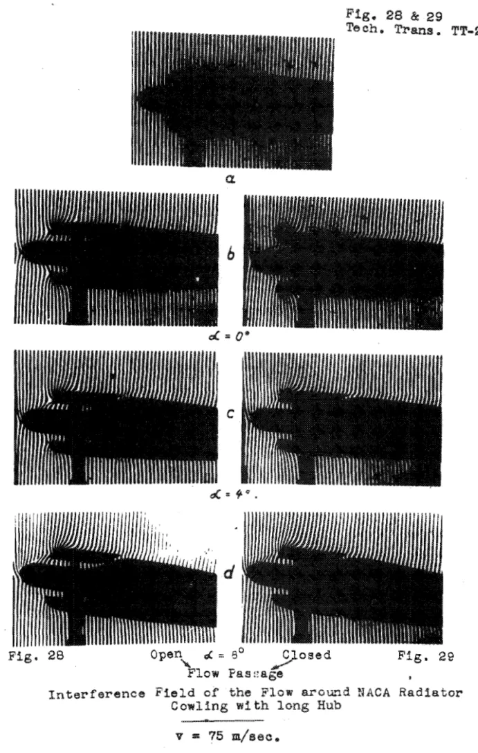
F i g u r e s 28 t o 31 show a s an example a plane model of a
NACA
r a d i a t o r cowling s u b j e c t e d t o a flow v e l o c i t y of75 metres p e r second, Two d i f f e r e n ? designs a r e shown:
one with a somewhat e x t e n d e d , , v e r y r'ounded hub, and t h e o t h e r wfth an o r d i n a r y ( N A C A ) , s h o r t hub only s l i g h t l y rounded; I n f i g u r e s 28 and 30 the flow passage i s open; i n f i g u r e s 29 and
31 i t i s plugged, Figure a g i v e s the undisturbed I n t e r f e r e n c e s t r i p f i e l d i n each case f o r no a i r flow; f i g u r e s b, e and d give t h e flow r e l a t i o n s h i p s a t t h r e e d i f f e r e n t a n g l e s of a t t a c k , 0 ° , 4 O and 8 ' ,
Even before a n a l y s i s t h e i n t e r f e r e n c e s t r i p p i c - t u r e s l e a d t o conclusions about the flow process on and w i t h i n the r a d i a t o r cowling pnd about t h e r e l a t i v e s u i t a - b i l i t y of the r e s p e c t i v e shapes, From the i n t e r f e r e n c e s t r i p p i c t u r e s we ape a b l e , by means of t h e simple a n a l y s i s i n - d i c a t e d on pages 5 and 6, t o deduce the p r e v a i l i n g v e l o c i t y a t every p o f n t on the hub and i n the flow channel,
Here, however, we might j u s t p o i n t out some d i f - f e r e n c e s i n connection w i t h t h e e v a l u a t i o n of the r a d i a t o r shapes which can be d i s c e r n e d even w i t h the eye, From the s h a r p d e v i a t i o n s of t h e i n t e r f e r e n c e s t r i p s n e a r the noses and from the way i n which they change a s the angle of a t t a c k i s a l t e r e d we recognize the presence of excess v e l o c i t y i n t h i s r e g i o n , With the,closed form I n f f g u r e 29, hub and cowling o p e r a t e a s a s i n g l e shape t o which the flow adheres, I t can be s e e n c l e a r l y t h a t a r e g i o n of s t i l l a i r forms in t h e closed flow passage around which the e x t e r n a l flow streams a s i f over a p r o f i l e contour,
F i g u r e s 28b, c and d show t h a t t h e excess speed on t h e pro j e c t i n g hub i s c o n s i d e r a b l y g r e a t e r than w i t h the c l o s e d shape, From t h i s we r e a l i z e t h a t when t h e r e i s a flow through t h e passage t h e two noses,
02
hub and cowlings,* form s e p a r a t e flow p r o f i l e s , The v e l o c i t y i n the flow pas- sage appears t o be a t i t s g r e a t e s t when-
-
4 O , whereas wfth = 8 O a s c r e e n i n g e f f e c t has a l r e a d y come i n t o opera-t i o n on t h e s u c t i o n s i d e , A t 8" the flow s t i l l adheres t o t h e nose of the hub,
I n f i g u r e s 28b and c, a s h a r p change i n d e n s i t y can be recognized behind t h e r e g i o n of g r e a t e s t excess
speed on the s u c t i o n s i d e of the hub, Thfs a p p a r e n t l y rep- r e s e n t s the t r a n s i t i o n from laminar t o t u r b u l e n t boundapy l a y e r , The p o r t i o n of t h e l a y e r l y i n g behind i t , i s unmis- t a k a b l y recongfzable a s t u r b u l e n t b o u n d a ~ y la y e r , merely from i t s c o n s i d e r a b l e t h i c k n e s s , The p o i n t of t r a n s i t i o n from laminar t o t u r b u l e n t l a y e r moves f a r t h e r forward w%th l a r g e a n g l e s of a t t a c k , The smooth p a r t of the cowling a c t s a s a f l a t p l a t e ,
Page
-
19 .Tech, T ~ a n s , TT-20 F i g u r e s 30 and Zl show t h a t evenson t h e s l i g h t l y rounded nose t h e f l o w breaks away a t a n a n g l e ~f a t t a c k of 0°, The d i f f e r e n c e between t h e i n c r e a s e d v e l o c i t y on t h e o u t e r body and t h e z e r o v e l o c i t y i n t h e c l o s e d f l o w passage i s c l e a r l y r e c o g n i z a b l e from t h e p i c t u r e s e r i e s 3 l b , e and d o The f l o w through t h e p a s s a g e - o f t h e r a d l a t o ~ with s h o r t hub e x e r t s a c o n s i d e r a b l y s t r o n g e r and l e g s f a v o w a b l e i n - f l u e n c e on t h e o u t e r f l o w than i s t h e - c a s e w i t h the d e s i g n i l l u s t $ a t e d i n f i g u r e 28, Even a t
a
= 4' we r e c o g n i z ea s h a r p i n c r e a s e i n t h e t h i c k n e s s of t h e boundary- l a y e r and '
an approach t o t h e c r i t i c a l s t a t e where t h e f l o w breaks away on t h e o u t e r p o r t i o n of t h e body, F i g w e 3Qd shows how, a t OI
=
8', t h e flow on t h e s u e t i on s i d e h a s a l r e a d y broken away from t h e o u t e r p o r t i o n of t h e cowling,Presumably t h e f avoukable e o n d i t f on of a t taehed flow could be a t t a i n e d merely by rouriding the s h o r t hub more and p u l l f n g i t j u s t s l i g h t l y forward, The s c r e e n e f f e c t h i n d e r i n g t h e flow through t h e passage a t l a r g e r a n g l e s of a t t a c k t h e n d i s a p p e a r s , Whether t h e f l o w i n t h e example of the l a s t named d e s i g n s t i l l a d h e r e s t o t h e body when t h e angle of a t t a c k fs r e l a t i v e l y l a r g e h a s - s t i l l t o be i n v e s t i g a t e d ,
A s a n a d d i t i o n a l example, i n t e ~ f e r e n c e p i e t u r e s of flow over a n o z z l e r a d i a t o r wfth a l a r g e flow opening a r e shown i n f i g u r e s 32 t o 35, I n f i g u r e s 32 and 33 a per- meable r e s i s t a n c e p l a t e c o n t a i n i n g h o r i z o n t a l s l i t s and h a v h g a t r a n s m i s s i o n of 50 p e r c e n t h a s been f i t t e d i n t o
t h e f l o w p a s s a g e , F i g u r e 32a shows ( s e e a l s o f i g u r e 7 ) how a t a s h o r t d i s t a n c e behind t h e r e s i s t a n c e p l a t e the d e n s i t y has been e q u a l i z e d t o an almost c o n s t a n t mean v a l u e over t h e e n t i r e c r o s s s e c t i o n , (None of t h e i n t e r f e r e n c e s t r i p f i e l d s h a s Seen ~ ~ e t o u c h e d i n any way:
1
We can determine t h e v e l o c i t y a t d i f f e r e n t p o i n t s i n the. flow passage d i r e c t l y from t h e displacement of t h e s t r i p s . The s e r i e s of p i c t u r e s i n t h e right-hand columns ( f i g , 33 and 3 5 ) shows t h e arrangement wfth a hinged f l a p , i n which a c o n s i d e r a b l e i n c ~ e a s e s f v e l o c i t y i n t h e f l o w passage can be recognized v e r y p l a i n l y , F i g u r e s 34 and 35 show t h e i n t e r f e r e n c e s t r i p p i c t u r e as f l o w p a s s e s through t h e open n - z z l e passage w i t h o u t and w i t h t h e hinged f l a p e f f e c t r e s p e c t i v e l y ,
These examples me>ely show how simply i n t e r f e r e n c e measurement p e r m i t s such experiments a t q u i t e a s m a l l t e c h - n i c a l e x p e r i m e n t a l expense (provided an i n t e r f e r o m e t e r 15 a v a i l a b l e ] . a n d a f f o r d s a glimpse of many p r o c e s s e s t h a t a r e s t i l l unknovrn o t h e r w i s e , The i n t e r f e r e n c e a n a l y s f s f u r n i s h e s t h e q u a n t i t a t i v e d a t a f o r t h e s e p r o c e s s e s ,
Page
-
20Tech, Trans, TT-20
The a p p l i c a t i o n of o p t i c a l measuring techniques growamore and more urgent a s f l y i n g speed i n c r e a s e s , f o r
they possess the g r e a t m e r i t of allowing us t o make processes v i s i b l e and measurable without the processes themselves
s u f f e r i n g any d i s t u r b a n c e whatsoever, Another g r e a t advan- tage connected with i n t e r f e r e n c e measurement is t h a t a l l p r e s s u r e h o l e s
in
the-model a r e e l i m i n a t e d and t h e manufac- t u r e of the once very comnplfoated m d expensive models(e,g, models with p r e s s u r e h o l e s f o r ha@ speed s t u d i e s )
i s
g r e a t l y s i m p l i f i e d , Moreover, from t h e p o i n t s f view of measuring technfque, i t i s very u s e f u l t o have every Y,ntar- f e r e n c e p i c t u r e , even those made a t high frequency on slow motion f f l m , c o n t a i n a l l t h e measurement d a t a of the t e s t process,
V I I SUblMARY_
A new o p t i c a l measurfng technique, developed in t h e Hermann Goering Aeronautica1.Researeh I n s t i t u t e a t Brun- awick, is described f o r simultaneous q u a l i t a t i v e a ~ d q u a n t i - t a t i v e r e p r e s e n t a t i o n of d e n s i t y f i e l d s surrounding bodies s u b j e c t e d t o flow, I t was worked out p a r t i c u l a r l y fop ex- periments under c o n d i t i o n s of compressible flow i n the h i g h speed wind tunnel. However, the r e s u l t s s o f a r obtained from preliminary t r i a l s w i t h t h e i n t e r f e r e n c e part of t h e measurfng equipment prove t h a t even a t o ~ d i n a r y v e b o c i t i e s
i t f s p o s s i b l e t o get d e n s i t y f ieLds t h a t we can e v a l u t a t e on bodies s u b j e c t e d t o flow,
Simple a n a l y t i cak rekatf onshfps gf ve t h e s o m e c - t i o n between d e n s i t y , a s obtained by L n t e ~ f e r e n c e of l i g h t , , and p r e s s u r e , v e l o c i t y and temperature on the t e s t body and i n i t s neighborhood, The proceaa of analysis
Fsr
pkessure d i s t r i b u t f o n I s explained and the u s e f u l n e s s of t h e method i s proven f n nume~f c a l examples, A t the moment work i s being done on the e v a l u a t i on of r e s i s tance by % n t e ~ f erenca,It 1s f u r t h e r shown t h a t the o p t i c a l measuring technique makes i t p o s s i b l e f o r t h e f i r s t time t o v i s u a l i z e t h e boundary Layer and t o o b t a i n - I t s quantf t a t i v e d a t a , Owfng t o t h e h i g h propagation speed cf U g h % akP phenomena i n the flow can be recorded by the o p t i c a l method e n t f r e l y without I n e r t i a , no m a t t e r how swIftBy t h e y take p l a c e , Because i t i s p o s s i b l e t o f n v e s t i g a t e events t h a t were
u t t e r l y beyond the scope of the previous measurfng technique, many more p o s s i b f l E t i e s of a p p l i c a t i o n ampfse for the i n t e r -
f e r e n c e method i n connection with a numbep s f new problems, We cannot y e t e s t i m a t e the e x t e n t of t h e s e p o s s k b i l i t i e a ,