HAL Id: hal-02191869
https://hal.archives-ouvertes.fr/hal-02191869
Submitted on 23 Jul 2019
HAL is a multi-disciplinary open access
archive for the deposit and dissemination of
sci-entific research documents, whether they are
pub-lished or not. The documents may come from
teaching and research institutions in France or
L’archive ouverte pluridisciplinaire HAL, est
destinée au dépôt et à la diffusion de documents
scientifiques de niveau recherche, publiés ou non,
émanant des établissements d’enseignement et de
recherche français ou étrangers, des laboratoires
for an Integrated Methodology
Nicolas Hili, Christian Fabre, Sophie Dupuy-Chessa, Stéphane Malfoy
To cite this version:
Nicolas Hili, Christian Fabre, Sophie Dupuy-Chessa, Stéphane Malfoy. Efficient Embedded System
Development: A Workbench for an Integrated Methodology. Embedded Real Time Software and
Systems (ERTS2012), Feb 2012, Toulouse, France. �hal-02191869�
Efficient Embedded System Development:
A Workbench for an Integrated Methodology
Nicolas Hili*, Christian Fabre*, Sophie Dupuy-Chessa**, St´
ephane Malfoy***
[email protected] – [email protected] – [email protected] – [email protected] * CEA LETI, bˆat. CTL, 7 av. de palestine, ZI de mayencin, F-38610 GI `ERES, FRANCE. ** LIG, bˆatiment IMAG C, 220 rue de la chimie, F-38400 SAINT-MARTIN-D’H `ERES, FRANCE.
*** Telecom Systems SA, En Budron E7, CH-1052 LE MONT SUR LAUSANNE, SUISSE.
ERTS
22012, February 1st–3rd, Toulouse, France
Keywords : Process Methods & Tools,
Model-Based System Engineering, Project Management, Progress Tracking, Co-Development, Traceability, Engineering Refinements.
Abstract
The scientific foundations of embedded system development associate two disciplines that have largely grown on their own: computer science and electrical engineering. This superposition of two domains with little common ground raises a num-ber of industrial issues in team work organisation, sound progress tracking, and cooperation between these different skills and cultures. In this paper we introduce hHOEi2, an integrated MDE method
for embedded system development that is organised around a set of limited yet powerful artefacts. We describe how hHOEi2 can address the issues faced during development of mixed HW/SW systems and present the first version of a tool dedicated to its instrumentation.
1
Introduction
Unlike other disciplines like civil engineering, em-bedded systems is a very young domain from both a scientific and an engineering point of view. There is a lack of unifying scientific foundation, as computer science and electrical engineering have evolved mostly separately so far [7]. Embedded sys-tem development teams have also to cope with the
usual constraints of industrial organisations whose main target is efficiency of teamwork at large. Crit-ical industrial concerns related to embedded system development include the following. End-to-End
Engineering: The full development cycle goes from requirement formalisation to the final integra-tion and assessment of the applicaintegra-tion on its plat-form. Hardware/Software Co-Development: HW & SW do not require the same set of skills. They are developed mostly independently while the quality of the final product highly depends on the smooth integration of both. Incremental &
Col-laborative: To organise efficiently the work of a
large team, it is critical to regularly show and mea-sure progress towards the objectives.
This paper presents the Highly Heterogeneous, Object-Oriented, Efficient Engineering method, shortened in hHOEi2. Highly Heterogeneous be-cause it aims to address both software (applica-tion code, middleware, operating systems, etc.) and hardware (ASIC, FPGA, etc.) development. Object-Oriented since hHOEi2 models are made of
objects linked by association and communicating through exchange of messages. Efficient Engineer-ing as it addresses industrial issues like traceability to requirements, team work synchronisation, in an integrated fashion.
The rest of this paper is organised as follows: sec-tion 2 presents related work. Secsec-tion 3 introduces hHOEi2. Section 4 applies it on a case study. And
finally section 5 presents a first version of a tool that supports hHOEi2.
2
Related Work
Seligmann, Wijers & Sol characterise a method in four ways: a way of thinking (the approach), a way of organising work (the process), a way of mod-elling (the models) and a way of supporting work (the tools) [20]. We will use their characterisation throughout the paper.
Modelling Languages. The standard way to model software systems is currently UML (Unified Modeling Language) developed by the OMG (Ob-ject Management Group) [17]. UML is a graph-ical language that provides several kinds of dia-grams, e.g. class diagram, sequence diagram, state-machine diagram. It has its roots in software mod-elling and is not bound to any specific domains. One area where plain UML falls short is Real-Time Embedded Systems (RTES). OMG proposed the MARTE profile for RTES development [15], and an extension for system engineering called SysML [16]. Several developments made with MARTE have been published. In [4], Demathieu et al. present first experiments using MARTE on the Josefil case study. They highlight the lack of UML for mod-elling RTES and present how MARTE was spec-ified to fill the gap of UML. In [22], Vidal et al. propose, among other things, a MARTE profile for platform modelling and VHDL code generation.
Processes. Of the ever increasing complexity of embedded systems, trend focused on combining methodologies related to both software (language-based methodologies) and hardware (synthesis-based methodologies) development [8]. Many ac-tors have contributed to this model-based trend. OMG proposed a new approach called Model-Driven Architecture (MDA) whose the three main goals of MDA are portability, interoperability and reusability [14]. MDA is based on the separation between the declaration of the application and its platform.
MDA is seen as a simplified vision of Model-Driven Engineering (MDE). MDE defines a soft-ware development approach which puts creation of models forward essentially and focuses on simple, transformable and manipulable models [5, 3]. MDE uses open standards like UML, and is based on sev-eral concepts (Executable models, transformations towards a specific platform, weaving).
With this new trend whose model is the cen-tral artefact, teams have to be organised through new working methods and development life cycles. Life cycles propose a defined number of phases and guide the developer in its work. Numerous pro-cesses have been proposed. The key properties are iterative and incremental, reusability of com-ponents, traceability across development from re-quirement to implementation, etc. Typical life cy-cles are Y life cycle, Waterfall life cycle or Twin Peaks life cycle [12, 13, 2].
Most Y-shaped life cycles share the following or-ganisation: the top-left branch represents the func-tional or application-related aspects of the develop-ment. The technical or platform-related aspects are captured in the top-right branch. And the central branch deals with integration of the application on the platform.
Capretz proposes in [12] a component-based Y life cycle which emphasises on the need of creat-ing reusable components. This life cycle relies on a separation between technical and functional as-pects. It is built on ten planned phases which are domain engineering, frameworking, assembly, archiving, system analysis, design, implementation, testing, deployment and maintenance. Its particu-larity is to incorporate the concern of reusability inside its life cycle.
In 1999, Unified Software Development Process (USDP) was born [11]. USDP is an iterative and incremental development process for software area. It is generic framework customizable for specific projects. Related to USDP are UP-based pro-cesses like Rational Unified Process (RUP) and Processus de D´eveloppement de Syst`emes Indus-triels (PDSI) [10, 18].
Based on UML, PDSI derives from USDP. It was proposed for distributing and communicating RTES and it is based on only four phases. PDSI claims a code reusability rate around 30% for the second project, and 50% for the third.
If these unified processes are the closest to our needs, almost do not clearly describe the transitions between each phase. Besides, no project manage-ment is integrated into them. They shall define regular checkpoints when it would be interesting to measure working progress etc.
Iterative and incremental notions are particu-larly important in Agile software development [1, 9]. Agile software development is a set of relevant
Efficient Embedded System Development: A Workbench for an Integrated Methodology 3/10
practices for software development. It proposes an iterative and incremental development and is found on four values: team and interactions, work-ing software, customer collaboration and respond-ing to change. In Agile software development, cus-tomers are an integral part of the development. Al-though Agile software development has proved its values in a Information System (SI) area, it is not applicable to embedded systems where software can not be independently developed without hardware. Besides, Agile software development does not ex-plain what artefacts have to be produced and how they are produced. This shortcoming explains why Agile methods are often coupled with another de-velopment processes.
To summarise, some approaches propose well de-fined concepts but there is no team organisation whatever (e.g. life cycles). Others define the way teams must be organised but do not explain what artefacts have to be produced (e.g. Agile meth-ods). Among those who say how the activities are organised, the transitions between each phase are not well described (e.g. USDP). Processes impre-cision, lack of guidance and project management inside current methods, processes non-applicable to both application and platform, etc. led to the proposition of new model-based methods.
Next section will present the hHOEi2 method.
3
The <HOE>
2Method
For our model-based method, we decided to rely on existing concepts used by others methods : an incremental development through an iterative ap-proach from Agile software development, reusabil-ity of components from Y model, independence of the platform by which MDE advocates that system specification must be independent from a specific platform.
This section presents the Highly Heterogeneous, Object-Oriented, Efficient Engineering method. The method is organised around four successive models which branch off each other by three En-gineering Refinements used to build those models gradually – see Fig. 1. The basic hHOEi2approach
is the following one.
Requirement Model. The informal require-ments are analysed and a Requirement Model is
Figure 1: The Four <HOE>2Models
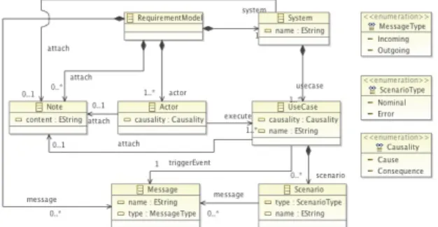
built. This static model includes the system, its actors, its use cases and their scenarios. Fig. 2 presents the Requirement metamodel that covers all notions defined above.
Figure 2: Requirement Metamodel
Analysis Model. This model is then refined into an executable, platform-independent Analysis Model. It is built through several, possibly recur-sive, Hierarchical Openings of objects. This refine-ment replaces an object with a set of objects that collectively exhibit the same apparent behaviour – see Fig. 4. Fig. 3 presents a piece of the Analysis metamodel.
Design Model. The platform is introduced par-tially by declaring its worlds. We define a platform as – within the meaning of MDA [14] – a set of sub-systems providing resources and hosting objects. A world is an abstraction for an execution domain that hosts objects – like a Digital Signal Processor (DSP), a set of processors and their shared mem-ory, a FPGA, or a future dedicated hardware IP.
Figure 3: Analysis Metamodel
Figure 4: Hierarchical Opening
Figure 5: Container Injection
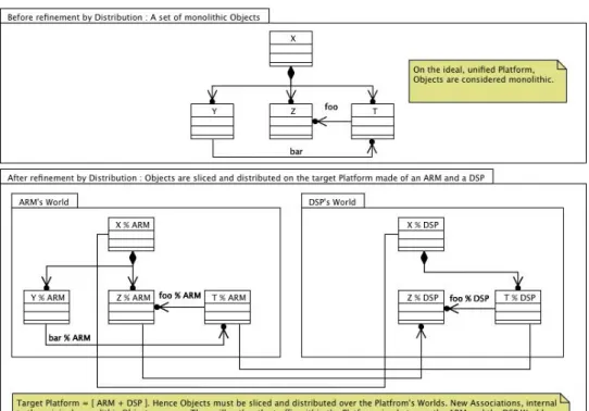
An executable Design Model is built, in which each object from the Analysis Model is distributed over the platform worlds – that is cut in slices with each slice hosted in a world, as shown Fig. 5.
To summarise, in the design phase we introduce a description of the platform limited to declaration of the worlds it supports. Then we distribute the analysis objects and associations on these worlds.
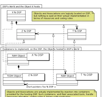
Implementation Model. On the occasion of the implementation phase, the platform is now fur-ther detailed: for each world, several containers are provided. Each of them embodies a given trade-off to implement object behaviour on the target exe-cution domain. The Implementation Model is then built by Injecting in a Container each object of the Design Model – see Fig. 6.
In this paper, we do not discuss further the se-mantics of container injection. But in a few words, an injection is legit if and only if the behaviour of the design model of an object is a proper abstrac-tion of the behaviour of its implementaabstrac-tion model.
4
The Camera Case Study
In order to illustrate the hHOEi2 method, we will
introduce a sample embedded system: a camera. This system covers the device that captures and stores the image. So as to make the example as simple and comprehensible as possible, we imag-ine a simple camera which lets the photographer take pictures and store that pictures into an inter-nal memory. After taking a picture, the photog-rapher can delete that picture, or list all pictures. Problems about memory will be ignored, in order to reject all use cases bound to the last one (“Store a Picture” at applicative level, “Check Available Memory Space” at platform level, etc.).
This section is organised as follows: first we will apply for this paper the first two phases of hHOEi2
method to the camera and its platform. Next, we will show how it addresses industrial concerns. Fi-nally, we will discuss industrial methods related to hHOEi2.
4.1
The Camera as a Case Study
Requirement Model of Camera. Fig. 7 shows the requirement model of the camera. We identi-fied one actor, the photographer. Camera proposes
Efficient Embedded System Development: A Workbench for an Integrated Methodology 5/10
Figure 6: Distribution
four identified use cases. Only “Take a Picture” and “Toggle Flash” use cases will be studied in this pa-per. We introduce here two stereotypes to classify actors and use cases regarding the system. These stereotypes are « Primary » and « Secondary ». A use case is labeled “Primary” when it is a cause of the system (the camera is designed to take pic-tures) and “Secondary” when it is a consequence of the system (the flash is a feature of advanced cameras).
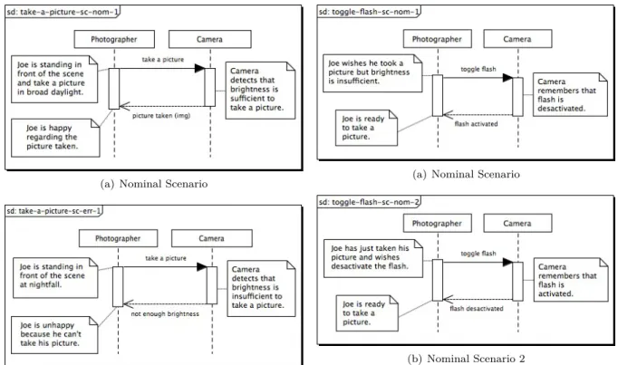
For each studied use case, we identify nominal and error scenarios. A scenario is labeled “Nom-inal” when it represents the nominal sequence of message exchanges between the actor and the sys-tem. An unexpected message or error causes the identification of an error scenario. Fig. 8 below shows a nominal (Fig. 8(a)) and error (Fig. 8(b)) scenarios of “Take a Picture” use case.
Note that both nominal and error scenarios from a same use case are activated by the same triggering event.
Use cases may have more than one nominal sce-nario, as well as they may own no error scenario. Fig. 9 presents two nominal scenarios of “Toggle
Figure 7: Requirement Model
Flash”. The second is an alternative of the first one. Both have the same triggering event. The in-ternal behaviour of the camera (more specifically the flash) will let us know which scenario will be played.
Analysis Model of Camera. We have now cap-tured a piece of requirement model, we can further extend our study. Fig. 10 shows the first
(a) Nominal Scenario
(b) Error Scenario
Figure 8: Scenarios of “Take a Picture”
chical opening of the camera. Before opening, the system appears as a black box (Fig. 10(a)). This opening reveals new objects (Fig. 10(b)): a sen-sor, images and also a flash. This opening might be done in more than one iteration, first iteration where we would have identified the sensor and im-ages so as to answer three first use cases specifi-cation, and a second iteration to discover a new object, the flash.
After carrying out the first opening of the cam-era, we can now refine all scenarios from the re-quirement model. Fig. 11 shows the refinement of the nominal scenario of “Take a Picture” use case. We can see that both triggering event and final an-swer from the system to the actor have not changed regarding the scenario in requirement model.
Dynamic aspects of each object are described from an analysis model by a Finite State Machine (FSM). The FSM points out what messages can be emitted or received by the object, and how the mes-sages are interpreted. Due to space limitation, the dynamic aspect are not addressed here.
(a) Nominal Scenario
(b) Nominal Scenario 2
Figure 9: Scenarios of “Toggle Flash”
Platform of the camera. The whole process of hHOEi2 can be applied at application level as well
as platform level. In this paper, we will tackle only the requirement model for the platform.
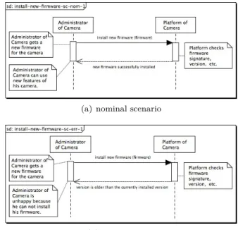
As shown in Fig. 12, we identify two use cases for the platform of the camera. Only one is studied here, the “Install New Firmware” use case. It lets the identified primary actor – Administrator – in-stall new firmware on the platform. Two scenarios have been captured for this use case (see Fig. 13(a) and Fig. 13(b)). The firmware to be installed is described as an object and passed as parameter to the platform, becoming a Shared Object of the re-quirement model – shared between an actor and the system. We can imagine several error scenar-ios, like “Corrupted Firmware”, “Attempt to Install Older Version of Firmware”, etc. The firmware is captured as the design model of the camera, and is the point of contact between the application and the platform development tracks.
Efficient Embedded System Development: A Workbench for an Integrated Methodology 7/10
(a) before opening
(b) after opening
Figure 10: 1st Opening of Camera
Figure 11: Refinement of Scenarios from Require-ment Model
Figure 12: Requirement Model of Platform
4.2
How hHOEi
2Addresses
Indus-trial Concerns
As we mentioned, hHOEi2 has a small number of
refinements and its models are precisely ordered. Three models out of the four are executable (i.e. they can be simulated or used to generate code) – only the requirement model is not. All this provides a number of side effects that can be exploited to address industrial concerns:
(a) nominal scenario
(b) error scenario
Figure 13: Scenarios of “Install New Firmware”
Traceability to Requirements: As the Anal-ysis, Design and Implementation models are ex-ecutable, they can be checked for conformance against the Requirement Model’s scenarios.
Non-Functional Analyses through Simula-tion: Instrumentation of models before and dur-ing execution enables non-functional property anal-yses, like performance analysis, through external tools and simulation.
Team Work: The ability to execute and animate models provide for a better understanding for all stakeholders of the system under construction.
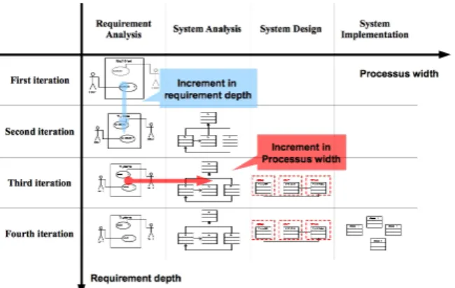
Iterations/Increments: The strict ordering of models can be the basis of iteration planning strate-gies. Fig. 14 shows the two axes involved in it-eration planning: requirement depth and process width.
Separation of Skills: The gradual introduction of the platform – first a pure topological descrip-tion, then extended with its containers – can be the basis of divide and conquer project manage-ment strategies. For instance, although application architects can be involved from requirement to de-sign, the fine grain details of implementation can
be handed to specialists of the platform, and be captured in containers definition and injection.
Toward a Platform Specific Model: hHOEi2
defines notions of Platform independent model (PIM) and Platform specific model (PSM) such as those depicted in [14]. hHOEi2 explains how we
hand PIM on to PSM.
Figure 14: Two Sets of Orthogonal Increments
4.3
Related Industrial Methods
hHOEi2 is loosely based on USDP. It shares
com-mon grounds with industrial processes for embed-ded systems, like PDSI.
The most obvious similarities are the following: a strict definition of what is a use case, in particular its unique triggering event; the absence of internal actors; the analysis phase where objects are purely abstract and platform-independent, followed by the design phase where objects are cut in pieces and dis-patched onto worlds; the replay of scenarios as the main evidence of progress; pervasive simulation to ensure model consistency and sharing across team members; a host of development traceability from requirement to implementation; a host of oppor-tunities for simulation to analyse various kinds of properties on the model.
The main difference are: clear separation be-tween design and implementation: first introduc-tion of the pure topology of the platform in Design, then of Container Injection for local code produc-tion in Implementaproduc-tion; the claim that the three refinements discussed below are necessary and suf-ficient to develop and model embedded systems.
Although not presented in this paper, hHOEi2 is
based on a key assumption: the four-phases process can be applied to the application and its platform, and the points of contact between the two mod-els are limited and precise. This assumption opens the door to a fully integrated process that would cover the complete life cycle of embedded systems, from requirement and exploration to implementa-tion, and from application to dedicated IP develop-ment. Such an integrated process is the ultimate goal of hHOEi2.
5
A
Tool
to
Support
the
Method
So as to take part in the good development of hHOEi2, we decided to develop a tool to support the
key point of the method: tight integration of arte-facts involved in development with those used to build consistent and efficient project management strategies. The tool will emphasise practical organ-isation of iterations based on the three refinements used in hHOEi2as a means for efficient project man-agement.
This section is structured as follows: first part will state our needs about modelling tools and plat-form development while second part will present a first version of the tool developed on the chosen development platform.
5.1
Tool Design
Each level of model will have an editor dedicated to its own refinement. Navigation in the models will be based on the logical ordering of refinements within models. The project management tool will support consistent planning and definition of iter-ations obeying the model refinement dependencies. The iteration history will be navigable.
User interface of our tool has to be split into three areas at a minimum:
Editor Area: An editor area which can be shared by the different textual and graphical ed-itors of each phase. For the graphical editors a palette has to be displayed and we must be able to drag and drop the entities from it. The information about the entities may be modified graphically in the editor, or in a property panel.
Efficient Embedded System Development: A Workbench for an Integrated Methodology 9/10
Navigator Area: A navigator lets us navigate inside our models. The navigator must be intuitive.
View Area: This area is dedicated to the project management and team work tools. We need to display some information like project management, team work, or some views to display and modify in-formation about the entities selected in the active editor.
5.2
Tool Implementation
We chose to develop our tool on the Eclipse plat-form. It lends itself rather well to our tool (Per-spective Management, Common Navigator Frame-work, Ecore Standard, etc.). It provides some tools to easily display multi-editors in the editor area, navigator and views.
The first step is to derive a well-formatted Ecore metamodel from our canonical metamodel. This step is fundamental since we need to consider the Ecore and its associated tool specificities. Fig.15 shows our requirement metamodel conformed to Ecore model.
Once we have produced our Ecore metamodel, we can apply the whole process of editor generation with the Graphical Modeling Framework (GMF) tools. GMF is a way to easily develop graphical editors binding Ecore model to the Graphical Edit-ing Framework (GEF) architecture [6]. We chose GMF rather than GEF for some reasons: defined and guided GMF process, model-based develop-ment, quick generation of graphical editors and re-duction of coding errors.
Fig. 16 shows our tool. It provides an editor ded-icated to the requirement model, a simple naviga-tor on its left and a property panel below the edi-tor area. The ediedi-tor was generated from the GMF dashboard [6], according to the Ecore Requirement Metamodel defining in Fig. 15.
6
Conclusion & Future Work
We have described hHOEi2, a method for embedded
systems development. We have detailed its organ-isation in four models and three refinements. We have also presented the first version of a tool that implements a subset of the method.
From this point, we will improve our tool on pro-cess width and requirement depth tacks. First in
Figure 15: Ecore Requirement Metamodel
Figure 16: The Workbench
process width, we will formalise the other stages of the hHOEi2 approach: design and implementation.
Next in requirement depth, we will extend our re-quirement and system metamodels with scenarios, objects, FSM, etc. and by implementing traceabil-ity between the models.
We only focus on notions from UML. As we said in section 2, UML is not well-suited for embedded systems. We need to study the integration of no-tions from MARTE, SysML and other profiles in-tended to add notions about embedded systems.
On the longer term, one of the key asset of hHOEi2 is its executable models. External tools
can provide feedback on the model, either through static analyses or simulation. This is clearly a key opportunity, as support for regular and systematic feedback on the model through out the develop-ment flow is not as pervasive in the embedded sys-tem industry as it is in other industries, like civil engineering and mechanics.
7
Acknowledgements
Christian Fabre & St´ephane Malfoy would like to thanks Bernard Rygaert, a former colleague from Groupe SILICOMP / ORANGE Business Services. Bernard was the leader and architect of PDSI, and he introduced them to the basics of simple, elegant and efficient object-oriented modelling.
The authors wish to thank Dominique Rieu for her comments for the paper and the discussions they have had around several modelling concepts.
Most pictures and diagrams presented in this pa-per have been made with the Papyrus MDT model-ing tool, developed by CEA LIST, now part of the Eclipse Modeling Framework [21, 19].
Last but not least, the authors would like to thank the reviewers of the extended abstract ver-sion of this paper for their insightful comments and suggestions.
References
[1] Kent Beck, Mike Beedle, Arie van Bennekum, Alistair Cockburn, Ward Cunningham, Martin Fowler, James Grenning, Jim Highsmith, An-drew Hunt, Ron Jeffries, Jon Kern, Brian Marick, Robert C. Martin, Steve Mellor, Ken Schwaber, Jeff Sutherland, and Dave Thomas. Manifesto for Agile software development, 2001. http:// agilemanifesto.org.
[2] B. W. Boehm. A Spiral Model of Software De-velopment and Enhancement. Computer, 21(5):61 –72, May 1988.
[3] Jean B´ezivin. On the Unification Power of Models.
Software and Systems Modeling, 4:171–188, 2005.
10.1007/s10270-005-0079-0.
[4] S. Demathieu, F. Thomas, C. Andre, S. Gerard, and F. Terrier. First Experiments Using the UML Profile for MARTE. In Object Oriented Real-Time
Distributed Computing (ISORC), 2008 11th IEEE International Symposium on, pages 50–57, May
2008.
[5] Jean-Marie Favre, Jacky Estublier, and Mireille Blay-Fornarino, editors. L’Ing´enierie Dirig´ee par les Mod`eles : au-del`a du MDA. Informatique et
syst`emes d’information. Hermes Lavoisier, 2006. [6] Richard C. Gronback. Eclipse Modeling Project
A Domain-Specific Language (DSL) Toolkit. The
Eclipse Series. Addison Wesley, 2009.
[7] Thomas A. Henzinger and Joseph Sifakis. The Dis-cipline of Embedded Systems Design. Computer, 40(10):32 –40, October 2007.
[8] Tom Henzinger and Joseph Sifakis. The embedded systems design challenge. In Proceedings of the
14th International Symposium on Formal Meth-ods (FM), Lecture Notes in Computer Science.
Springer, August 2006.
[9] Jim Highsmith and Martin Fowler. The Ag-ile Manifesto. Software Development Magazine,
9(8):29–30, 2001.
[10] IBM. Rational Unified Process: Best Practices for Software Development Teams, December 2003. [11] Ivar Jacobson, Grady Booch, and James
Rum-baugh. The Unified Software Development Process. Addison Wesley, February 1999.
[12] Luiz Fernando Capretz. Y: A New Component-Based Software Life Cycle Model. Journal Of Computer Science, 1:1, 2005.
[13] B. Nuseibeh. Weaving Together Requirements and Architectures. Computer, 34(3):115 –119, March 2001.
[14] Object Management Group, Framingham, Mas-sachusetts. MDA Guide Version 1.0.1, June 2003. [15] OMG. UML Profile for MARTE: Modeling and
Analysis of Real-Time Embedded Systems v1.0,
November 2009.
[16] OMG. Systems Modeling Language Specification
v1.2, July 2010.
[17] OMG. Unified Modeling Language Specification 2.3, April 2010.
[18] Bernard Rygaert. PDSI: Processus de D´eveloppement des Syst`emes Industriels, 2002. Marketing flyer from Silicomp.
[19] Sebastien Gerard. Papyrus Home Page. http: //eclipse.org/papyrus.
[20] P.S. Seligmann, GM.M. Wijers, and H.G. Sol. An-alyzing the Structure of I.S. Methologies, an Alter-native Approach. In Proceedings of the First Dutch
Conference on Information Systems, 1989.
[21] S´ebastien G´erard, C´edric Dumoulin nad Patrick Tessier, and Bran Selic. Papyrus: A UML2 tool for
Domain-Specific Language Modeling, volume 6100.
Springer Verlag, 2010.
[22] J. Vidal, F. de Lamotte, G. Gogniat, P. Soulard, and J.-P. Diguet. A Co-Design Approach for Em-bedded System Modeling and Code Generation with UML and MARTE. In Design,
Automa-tion Test in Europe Conference ExhibiAutoma-tion, 2009. DATE ’09, pages 226–231, April 2009.