HAL Id: hal-03213402
https://hal.archives-ouvertes.fr/hal-03213402
Submitted on 3 May 2021
HAL is a multi-disciplinary open access
archive for the deposit and dissemination of
sci-entific research documents, whether they are
pub-lished or not. The documents may come from
teaching and research institutions in France or
abroad, or from public or private research centers.
L’archive ouverte pluridisciplinaire HAL, est
destinée au dépôt et à la diffusion de documents
scientifiques de niveau recherche, publiés ou non,
émanant des établissements d’enseignement et de
recherche français ou étrangers, des laboratoires
publics ou privés.
Distributed under a Creative Commons Attribution| 4.0 International License
operation
Frank Wilhelms, Heinrich Miller, Michael Gerasimoff, Cord Drücker, Andreas
Frenzel, Diedrich Fritzsche, Hannes Grobe, Steffen Bo Hansen, Sverrir Æ.
Hilmarsson, Georg Hoffmann, et al.
To cite this version:
Frank Wilhelms, Heinrich Miller, Michael Gerasimoff, Cord Drücker, Andreas Frenzel, et al.. The
EPICA Dronning Maud Land deep drilling operation. Annals of Glaciology, International Glaciological
Society, 2014, 55 (68), pp.355-366. �10.3189/2014AoG68A189�. �hal-03213402�
The EPICA Dronning Maud Land deep drilling operation
Frank WILHELMS,
1* Heinrich MILLER,
1†Michael D. GERASIMOFF,
2Cord DRÜCKER,
1Andreas FRENZEL,
1Diedrich FRITZSCHE,
1Hannes GROBE,
1Steffen Bo HANSEN,
3Sverrir Æ. HILMARSSON,
1Georg HOFFMANN,
4Kerstin HÖRNBY,
5Andrea JAESCHKE,
1Steinunn S. JAKOBSDÓTTIR,
1Paul JUCKSCHAT,
1‡Achim KARSTEN,
1Lorenz KARSTEN,
1Patrik R. KAUFMANN,
6§Torbjörn KARLIN,
5Eberhard KOHLBERG,
1Guido KLEFFEL,
1¶Anja LAMBRECHT,
1jjAstrid LAMBRECHT,
1** Gunther LAWER,
1††Ivan SCHÄRMELI,
6Jochen SCHMITT,
1‡‡Simon G. SHELDON,
3Morimasa TAKATA,
7Marcus TRENKE,
1Birthe TWARLOH,
1Fernando VALERO-DELGADO,
1Dorothee WILHELMS-DICK
1 1Alfred-Wegener-Institut Helmholtz-Zentrum für Polar- und Meeresforschung (AWI), Bremerhaven, Germany E-mail: [email protected]
2
Dynamic Devices, Lethbridge, Alberta, Canada
3
Centre for Ice and Climate, Niels Bohr Institute, University of Copenhagen, Copenhagen, Denmark
4
Laboratoire des Sciences du Climat et de l'Environnement (LSCE/IPSL/CEA/CNRS/UVSQ), Gif-sure-Yvette, France and Institute for Marine and Atmospheric Research Utrecht (IMAU), Utrecht University, Utrecht, The Netherlands
5Department of Physical Geography, Stockholm University, Stockholm, Sweden 6
Climate and Environmental Physics, Physics Institute, University of Bern, Bern, Switzerland
7
Department of Mechanical Engineering, Nagaoka University of Technology, Nagaoka, Niigata, Japan
ABSTRACT. We report on the EPICA Dronning Maud Land (East Antarctica) deep drilling operation. Starting with the scientific questions that led to the outline of the EPICA project, we introduce the setting of sister drillings at NorthGRIP and EPICA Dome C within the European ice-coring community. The progress of the drilling operation is described within the context of three parallel, deep-drilling operations, the problems that occurred and the solutions we developed. Modified procedures are described, such as the monitoring of penetration rate via cable weight rather than motor torque, and modifications to the system (e.g. closing the openings at the lower end of the outer barrel to reduce the risk of immersing the drill in highly concentrated chip suspension). Parameters of the drilling (e.g. core-break force, cutter pitch, chips balance, liquid level, core production rate and piece number) are discussed. We also review the operational mode, particularly in the context of achieved core length and piece length, which have to be optimized for drilling efficiency and core quality respectively. We conclude with recommendations addressing the design of the chip-collection openings and strictly limiting the cable-load drop with respect to the load at the start of the run.
KEYWORDS: Antarctic glaciology, glaciological instruments and methods, ice-core drilling
1. INTRODUCTION
The European Project for Ice Coring in Antarctica (EPICA) acquired two deep ice-core records from East Antarctica. The EPICA Dome C (EDC) deep ice core is, to date, the longest continuous immediate atmospheric record, allowing cli-matic reconstructions about 800 ka back in time (EPICA
Community Members, 2004). This paper concerns the drilling operation of the sister record in the Dronning Maud Land (DML) area. The DML core provides a high-resolution record of South Atlantic climate history and complements the Greenlandic ice-core records, allowing a common interpret-ation of global ocean circulinterpret-ation and that circulinterpret-ation’s influence on surface water temperature in the North and South Atlantic region (EPICA Community Members, 2006). We touch briefly on the history of the EPICA project before focusing on the drilling operational mode and its effect on EPICA-DML (EDML) core quality and core retrieval effi-ciency. The EPICA project has led to more than 250 publications; for a recent compilation that includes these EPICA publications, among other scientific outcomes, the reader is referred to the joint Climate of the Past–The Cryosphere special issue Climate of the Past (http://www. clim-past.net/special_issue55.html), an outcome of the Inter-national Partnerships in Ice Core Sciences (IPICS) First Open Science Conference held in Giens, France, on 1–5 October 2012. At that conference Jouzel (2013) presented a detailed
*and Department of Crystallography, Geoscience Centre, University of Göttingen, Göttingen, Germany.
†and University of Bremen, Germany.
‡Present address: Berufliche Schule für Technik, Bremerhaven, Germany. §
Present address: ABB Switzerland Ltd, Corporate Research, Baden-Daettwil, Switzerland.
¶Present address: Züblin Umwelttechnik GmbH, Stuttgart, Germany. jjPresent address: DMT GmbH & Co. KG, Essen, Germany.
**Present address: Kommission für Erdmessung und Glaziologie, Bayerische Akademie der Wissenschaften, München, Germany.
††
Present address: IT-Wizards GmbH, Taunusstein, Germany.
‡‡Present address: Climate and Environmental Physics, Physics Institute and Oeschger Centre for Climate Change Research, University of Bern, Bern, Switzerland.
overview of ice-core projects during the past 50 years. The scientific data archive for the EPICA project may be found at http://www.pangaea.de/search?q=project:epica.
2. FORMULATION AND FUNDING OF THE EUROPEAN PROJECT FOR ICE CORING IN ANTARCTICA
After the great success of the Greenland Ice Core Project (GRIP) (GRIP members, 1993), the European ice-core research community met for a scoping workshop (14– 18 September 1993) at Aghia Pelagia, Crete, which was funded by the European Science Foundation (ESF). The outcome of that workshop was a focus on two new drilling sites that seemed most suited to answer pressing scientific questions that had to be addressed by polar ice-core studies. Extending the atmospheric record beyond the available 420 ka in the Vostok (Antarctica) record (Petit and others, 1999) was a most valuable contribution to palaeoclimate reconstructions. The Dome C area of Antarctica, where France and Italy planned to build the wintering station ‘Concordia’, was a promising spot to acquire a 500 ka record strongly influenced by the South Pacific. The other pressing question was whether evidence for Dansgaard– Oeschger-like cyclic behaviour existed in a high-resolution ice-core record from the Atlantic-influenced sector of Antarctica and, if such evidence did not exist, then, at a minimum, to provide data for interhemispheric comparison during one full glacial cycle. A promising area to acquire a high-resolution ice-core record to represent the South Atlantic and complement the Greenlandic ice cores in a common interpretation was the plateau of Dronning Maud Land south of the German wintering base, Neumayer. When EPICA was formulated, Germany and the United Kingdom were prepared to logistically support this focus of the project. Funding (25%) for EPICA fieldwork was provided by three subsequent grants within the 4th–6th European Framework Programme. Seventy-five per cent of the funds came from the ten national contributors to the programme. The ESF made funds available for coordination.
The GRIP and Greenland Ice Sheet Project 2 (GISP2; Grootes and others, 1993) ice-core records were disturbed by ice-flow folds in the Eemian ice interval. A consortium met and formulated the NorthGRIP (NGRIP) deep-drilling project (NorthGRIP members, 2004) shortly afterwards, at the GRIP/ GISP2 intercomparison workshop at Wolfeboro, NH, USA, in September 1995. The NGRIP project was designed to retrieve an undisturbed Eemian record from Greenland. NGRIP was later associated with EPICA, as the driving partners of EPICA and NorthGRIP intersected in large part.
3. EPICA–NorthGRIP DRILL DEVELOPMENT; NGRIP, EDC AND EDML DEPLOYMENT
While planning the EPICA operation it was clear to the drilling experts that the ISTUK drill (Johnsen and others, 1994), which had been deployed successfully in the Dye-3 and GRIP deep ice-core drilling in Greenland, was not suited for much lower temperatures, especially those at EDC, due to problems with seals (Johnsen and others, 2007). Experts under the supervision of the late Niels Gundestrup were tasked with developing a new drill system suited for deployment at both Antarctic EPICA sites. It would be tested during the NGRIP deep drilling operation before EPICA
deployment. A short version of the drill was tested on Hans Tausen ice cap in 1995 and is now referred to as the HT design. The 11 m long version of the drill was used to acquire the uppermost 350 m of the NGRIP core during summer 1996 before casing-setting operations at EDC started during the 1996/97 austral summer; EDC deep drilling started during the 1997/98 austral summer. Un-fortunately, neither drill could be extracted from the hole from 1371 m at NGRIP during the 1997 summer (Gundes-trup and others, 2002) and 783 m at EDC during the 1998/ 99 austral summer (Augustin and Antonelli, 2002). While the original plan was to move the drilling infrastructure from EDC to EDML after completion of the EDC hole, these incidents resulted in delays to both operations. Commence-ment of an entirely new bore at EDC on 11 December 1999 implied that EDML operations could not be started in time. At NGRIP a new hole had already been started during summer 1998, and plans were altered: the ‘underground’ section from NGRIP would eventually move to EDML, and new surface equipment (e.g. the tower, winch and liquid-handling system for EDML operations) would be acquired.
During the 2000/01 austral summer, the drill trench and a pilot hole were installed at Kohnen station, which had been erected at the drill site (Drücker and others, 2002; Oerter and others, 2012). As NGRIP had reached 2930 m during summer 2000, we decided to proceed further with the short 4 m long version of the drill at NGRIP, and the plan was to move the 8 m long version of the drill to EDML and start the deep drilling in the 2001/02 austral summer. However, the electronics sections and all the mechanical parts (e.g. valves, drill heads, pumps, couplings, spare parts and the ‘short’ (4 m long) version of the drill) were shared between projects; these items were shuttled back and forth between Kohnen station and NGRIP every season till NGRIP reached the bottom of the ice sheet a second time, after re-drilling the refrozen water that had entered the hole during the 2003 summer. The decision, forced by circumstances, to share the drill equipment between hemispheres resulted in a heavy maintenance load in the field, and expensive logistics options (e.g. air freight) as we usually shipped equipment immediately from one drill site to the other. In any case, the abovementioned originally planned transfer of the drill from EDC to EDML never took place because the EDC drill (together with other equipment) was stolen from Hobart (Australia) harbour while being shipped back to Europe after the 2002/03 season (Augustin and others, 2007a).
4. EDML DRILLING OPERATION: DIARY, MODIFICATIONS, MANNER AND RESULTS
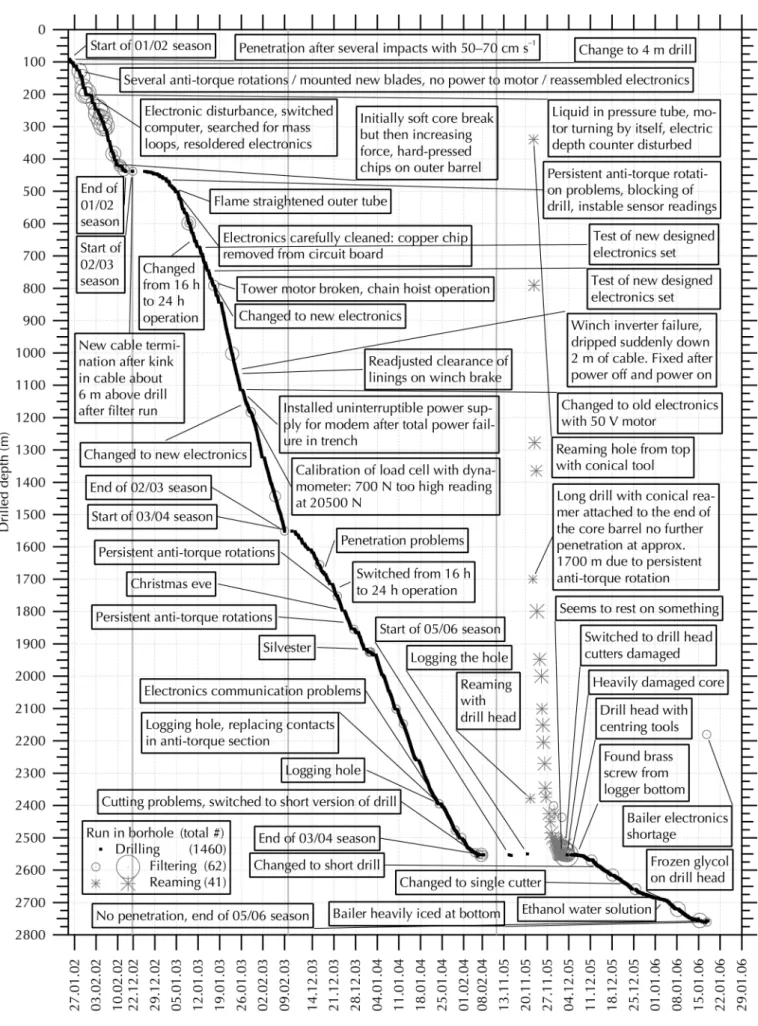
Efficient drilling depends on reliable, well-designed equip-ment. Such equipment was, in principle, available, although the above-mentioned logistic constraints allowed little to no maintenance intervals between boreal and austral seasons. It was also necessary to debug newly designed electronics during running-drill operations. Fortunately, we had an un-debugged prototype of new downhole electronics under development when the old electronics section (still in use since the Dye-3 project; Gundestrup and others, 1984) broke down during the NGRIP 2001 season. Figure 1 shows the penetration for the deep drilling operation by displaying the drilled depth versus time. The tick marks and grid indicate the changeover from Saturdays to Sundays, with a ‘Saturday night’ break for staff between late Saturday
Fig. 1. Commented drilled depth vs time for the four deep drilling seasons. Circles for filter run with chip collection 0–12 kg, stars for
afternoon and about Sunday noon clearly identifiable as little saddle points in the curve. The drilled depth is typically �12.6 m (the offset between the snow surface at the start of the drilling project and the top of the casing) shallower than the logging depth, as the drill’s depth counter is zeroed before starting a run, when the drill is freely hanging above the casing top. This must be borne in mind when comparing any depth reference presented here with core data that refer to the logging depth. The complete drilling protocol and other supplementary information can be found at http://doi. pangaea.de/10.1594/PANGAEA.841035, and is summar-ized in the remarks attached to the curve in Figure 1. Table 1 gives an overview of the seasonal progress of the deep drilling operation. The excursion of the penetration is discussed below in a short diary; experiences that led to a fundamental change in procedure are highlighted and discussed further below.
4.1. Diary of the EDML seasons
During the 2000/01 season, Kohnen station was completed as a base to host the drilling operation. A 4.8 m wide, 5.88 m deep trench to accommodate the drilling operations was excavated from the surface and covered by a wooden roof. The base of the inclined trench is 6.54 m below the floor of the trench. A 104 mm diameter bore to accommodate casing was drilled with the Danish shallow 3-inch drill (Johnsen and others, 1980) to 100.3 m drilled depth, which refers to approximately the inclined trench’s base and is 112.99 m below the surface. The hole was reamed with the Danish reamer set to the following diameters to the respective drilled depths: 135 mm diameter to 95.1 m, 183 mm diameter to 87.5 m, 222 mm diameter to 85.7 m and 255 mm diameter down to 85.20 m. Finally, 200 mm diameter casing tubes manufactured by Kurotec-KTS Kunststofftechnik Stade GmbH in the same dimensions and construction as de-scribed by Johnsen and others (1994) were installed.
At the beginning of the 2001/02 season, the drilling equipment was transported, after some delays due to heavy sea ice, by surface traverse to Kohnen station (Oerter and others, 2012). After arrival of the drilling and science crew by plane and a few days of acclimatization to altitude, the drill and science-trench infrastructure was installed, the drill workshop was furbished and finally a 2.5 week drilling operation was possible. After partial filling of the bore with a blend of D40 and HCFC-141b drilling liquid (Talalay and Gundestrup, 1999, 2002), drilling in the stepped section between the lower end of the casing and the end of the
3-inch hole commenced, and we recovered regular core of 98 mm diameter in a 129.6 mm diameter hole below 100.81 m drilled depth. The drill team, which had seven to nine members, drilled �16 hours d–1 between 08:00 and
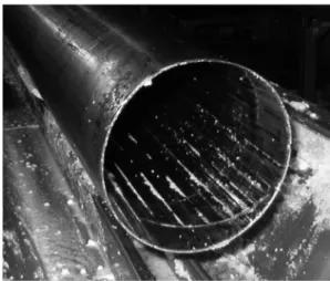
24:00. The drilling went smoothly; anti-torque rotation (slippage) problems were a nuisance but did not prevent core production. Many of the electronics problems, which we could not resolve immediately, were most likely caused by a defective inclinometer, which leaked silicon oil onto the circuit boards. The defective inclinometer was replaced during the final drilling season. The anti-torque rotation errors identified by the electronics were most likely false readings, as defective inclinometers are much more prone to rattling: they are filled with silicon oil to damp vibration. As the indication of drill (‘anti-torque’) rotation is generated from the difference between two inclinometer readings, excessive noise on one signal leads to erroneous anti-torque-failure indications and stop-rotation triggers. During run 138, we encountered an almost-blocked drill due to com-pacted chips on the outside of the outer barrel (see Fig. 5). We then fundamentally changed the approach to pene-tration (see Section 4.2). The rest of the season was uneventful, and we ceased drilling at 438.8 m drilled depth (450.95 m logging depth).
The second deep-drilling season (2002/03) started with modifications to the drill. To prevent chips moving upward outside the outer barrel, we modified the outer tube as described in Section 4.3. The mounting of the new drill electronic sections consumed several days in the field, as some parts were directly shipped from NGRIP and new pressure tubes, gear sections and top plugs were delivered so late, because of delays in the ordering process, that we could not assemble them back home. After cautious preparations, we started operations by training new drillers during a long day shift, and after �2 weeks we split into two shifts operating from morning till midnight. After �3 weeks, we tested operations during the overnight (early morning) period and soon changed to three-shift round-the-clock operations. As illustrated by the penetration curve in Figure 1, the season continued with good production, albeit with identifiable disturbances in the electronics; we protected the system against power failures by installing uninterruptible power supplies and by implementing other details to optimize the installed system. We stopped at 1551.55 m drilled depth (1564.5 m logging depth), having produced 1114 m of ice core during 7 weeks of drilling.
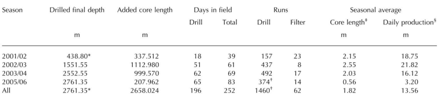
Table 1. Seasonal progress of the deep drilling operation
Season Drilled final depth Added core length Days in field Runs Seasonal average
Drill Total Drill Filter Core length‡ Daily production§
m m m m 2001/02 438.80* 337.512 18 39 157 23 2.15 18.75 2002/03 1551.55 1112.980 51 61 437 8 2.55 21.82 2003/04 2552.55 999.570 62 69 492 17 2.03 16.12 2005/06 2761.35 207.962 65 83 374† 14 0.56 3.20 All 2761.35* 2658.024 196 252 1460† 62 1.82 13.56 *Starting from bottom of casing hole at 100.95 m drilled depth.
†The hole was enlarged with 41 reaming runs at the beginning of the season. ‡
Added core length divided by number of drill runs. §
We started the third deep-drilling season (2003/04) with training of drillers, and operated for �2 weeks between morning and late evening, before implementing operations around the clock. Drilling, in general, progressed smoothly. We encountered penetration problems from time to time and these became severe towards the end of the season at 2538 m (�2550 m logging depth). We stopped at 2552.55 m drilled depth (2565 m logging depth) after producing 1001 m of ice core in almost 9 weeks of drilling.
After pausing for one full season to allow us to better prepare for the often problematic warm-ice drilling, and as we had in fact achieved the promised recovery of marine isotope stage (MIS) 5.5 ice during the third deep-drilling season and were well within the glacial MIS6 below �2400 m, we started the final deep-drilling season (2005/ 06) by logging the bore. The log was mainly to record the initial temperature profile. To our surprise, the initial bore log displayed a rapidly increasing bore closure of up to �2.5% in diameter (�3 mm for the 129.6 mm hole) in the lowermost part (i.e. below 2373 m drilled depth or �2385 m logging depth), where the underpressure in the hole was, by our best estimate, not more than 0.4 MPa below 1000 m. After experiencing ‘anti-torque’ (drill) rotations during unsuccess-ful attempts to ream the lower part of the hole (below 2378 m) using the drill head followed by a conical scraper (for a picture, see Talalay, 2013, fig. 33) we decided to ream the hole with the conical scraper from 1770 m downward. It took us 9 days to ream the hole to 130 mm diameter down to 2425 m, and another 6 days to reach the bottom at 2552 m. By reaming the hole with a slightly oversized reamer, we were able to increase the tripping speed considerably. The reaming essentially reset the diameter for future bore logs, allowing future study of closure in more detail. Figure 1 shows the progress of the reaming.
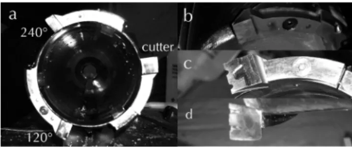
When we resumed drilling after reaming, we immediately brought up a heavily damaged core piece (Fig. 2a). It then became obvious that we had a previously unrecognized obstacle in the borehole. We tried to recover the obstacle from the hole on the top of a newly cut core by moving it to the centre line of the bore using centring tools (Fig. 2b). After drilling short cores and trying to induce a bottom break using blunt core catchers, we recovered a piece of brass (�30 mm diameter; Fig. 2c). We later correlated that item with the bottom indicator of the Danish bore logger (Gundestrup and others, 1994). For the rest of the season we stayed with the short version of the drill, as attempts with the long version did not produce longer cores. From
2642.41 m drilled depth, we drilled with one sharp cutter only, and two cutters ground with 0° relief angle and a rounded edge used solely to define the pitch (Fig. 3b). That is to say, the ground cutter 120° of rotation behind the cutting edge had a clearance of one-third of the desired pitch, while the other one at 240° of rotation behind the cutting edge had a clearance of two-thirds of the desired pitch (Fig. 3a). Below 2681.64 m, we switched to a cutter with reduced contact area and chip-breaker grooves (Fig. 3c and d). Below 2691.81 m we used 50% (v/v) ethanol–water solution (EWS), applied as described in Johnsen and others (2007) but in substantially smaller quantities, between 50 and 200 mL, typically 110 mL per run. We tuned the volume of EWS depending on the course of the prior run. The EWS should have been consumed by the end of a run, a conclusion we arrived at from loss of penetration. The deepest plumbing was 2761.77 m and we reached 2774.15 m logging depth on 16 January 2006. We terminated drilling as subglacial water was then rising faster in the hole than we could remove it, and we recovered refrozen water on the tools we deployed: the logger, the bailer (Fig. 4a) and the drill (Fig. 4b).
4.2. Permissible drop in cable weight as a key parameter
During the start of the first season we drilled principally in the same manner as at NGRIP: the operator at the console adjusts cable-feed rate according to the torque required for rotation, which is indicated by the current drawn by the drill motor. If the current increases, the operator adjusts cable feed rate so as to penetrate slower, and might even stop and idle until the current drops to normal levels. When drilling between 416.69 and 418.86 m (run 138 in the above-referenced drilling protocol), the cable load, i.e. the reading of the load cell in the top tower wheel, was decreased to �–33 decanewtons (daN) lower than the start of the run and penetrated this way for several minutes. Penetration was stopped and idled for some time, as we attributed the
Fig. 2. (a) Heavily damaged core retrieved from 2552.5 m during
run 1187, (b) centring tools and (c) 30 mm brass piece.
Fig. 3. (a) Single-cutter drill head with ground cutter 120° and 240°
behind cutter. (b) Ground cutter with 0° relief angle, cutter with less contact area and chip-breaker grooves, (c) bottom view and (d) top view.
decreased pull of the drill to friction from chips collected around the outer barrel. After idling with concurrent pumping for several minutes and noting a slight increase in cable load, we pulled up. The core broke at a low pull of 479 daN. However, the load then increased after we had pulled up �3 m of cable, and we stopped at 900 daN. While exerting and releasing loads of up to 900 daN and rotating the drill head, the drill finally came free. At the surface we observed three, 40 cm long, �1.5 cm wide, very hard-pressed chip cakes along the lower part of the outer barrel. These were just above the openings at the lower end of the outer barrel. The pressed chips presented in the photograph in Figure 5 could hardly be scraped off with a screwdriver. The 2.15 m long core closely matches the 2.17 m penetrated depth. We interpreted the observed as follows: The pumping action was too weak to remove the generated chips at the given penetration speed. In principle, the spiral action piles up chips in the openings while only a fraction of them are captured by the spirals; a reasonable fraction of the chips is prone to be squeezed between the outer barrel and hole wall, while the drill slips past those chips, following the cutting action. Those chips are never recaptured by the drill, as the downward volumetric flow rate and therefore the flow velocity is too small to entrain them and move them back into the gaps in the cutter head. They create drag acting to prevent downward movement of the drill, and thus result in decreased cable load at a given cable payout rate. When pulling up, the core broke but the chips in the annulus were compacted, compressed and, as a result, wedged the outer barrel against the bore. The chips are compacted above the openings at the lower end of the core barrel, which is designed to enable the chips entering the annulus between the core barrel and outer barrel to be transported up into the chip chamber. At least in the scenario during the reported run, the openings seemed to increase the dangerous likelihood of chips moving into the annulus between the outer barrel and bore wall. This underlines the role of cable load as a key observational parameter, as the course of the run did not otherwise differ from comparable runs.
To prevent similar incidents in the future, we changed the manner of drilling. Further penetration was judged on the hanging load exerted by the drill rather than using motor current as a proxy for torque alone. The operator adjusted cable feed so that the cable load remained stable. This is
possible by employing a very precise winch control that permits setting the cable feed resolution to as low as a few tenths of a mm s–1. By stepping the control one digital increment up or down, the operator aims to keep the cable load constant within 1–2 daN. Throughout the run, the cable load will usually drop slightly as drag rises with the increasing length of core filling up the core barrel. If the cable load drops by >5–10 daN, advance is temporarily halted; either the load decreases while idling and pumping, or the run is terminated. Ultimately, too much drop in cable load indicates that the circulation is not removing the chips effectively.
4.3. Closed openings at the lower end of the core barrel
To mitigate the problem of chips moving up into the annulus between the outer barrel and the borehole wall, we decided to close the openings in the outer barrel by welding-in triangular pieces (Fig. 6). Thus, we eliminated the possibility of actively moving chips in the outer annulus through the spiral action. Chips are stirred by the drill head till they eventually move to the inner (upward flow) annulus where they are transported away. To provide enough space for the chips to enter the drill between the core barrel and outer barrel we moved the core barrel �1 cm down compared with the outer barrel, by inserting custom-made washers at the mounting point of the core barrel valve, thus forming a space where the chips can enter what we determined to be the proper space between the outer barrel and core barrel around the entire circumference.
4.4. Core break policy for optimized core quality and sustainability of the operation
After loss of penetration without having retrieved an almost-full core barrel, the common procedures during the first season were to break the core and try to penetrate again. As the project proceeded, we changed this to an increasingly strict policy of breaking the core and restarting penetration not more than once, or not re-penetrating at all; we would abort the run, pull up, and start the next run with a clean core barrel. We thereby avoided leaving chips due to inefficient removal by circulation from a bad run before. Furthermore, we limited the initial maximal pull to break the core at a certain limit where we experienced the core would normally break after resting at the load for a few seconds.
Fig. 6. Closed lower openings of the outer barrel after welding-in
triangular metal pieces.
Fig. 5. Hard-pressed chips at the lower end of the outer barrel after
Besides the above-mentioned advice to the operator, we also adjusted the current limit in the winch control according to the calculated maximal permissible torque for a slightly higher, system-limited maximal pull. This was to prevent accidental, very hard pulls. Figure 7 shows the recorded core breaks and the correction for cable weight.
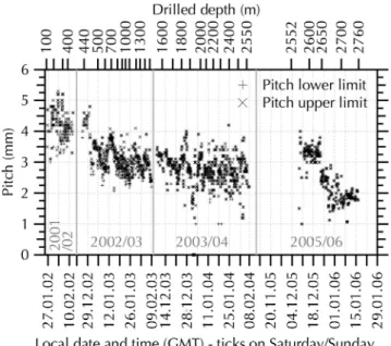
4.5. Balancing chips-generation and pumping action by adjusting cutter pitch
As described above, we attempted to limit the apparent drop of cable tension throughout the run to ensure the chips’ removal by only progressing with efficient circulation. Driving the pump from the main shaft, i.e. synchronized with the rotation of the drill head, means that the cutter pitch is the sole parameter adjusting the rate of generation of chips to what the pump is able to suck away. Figure 8 illustrates the pitch we maintained, with relatively high values (�4–5 mm) during the first season, slightly less (3–4 mm) during the second season and as low as 1–3 mm in the lowermost ‘warm ice’ part. In the warm-ice situation, we used the previously described arrangement having only one sharp cutter; this generated coarse chips at low pitch and limited heat generated by cutting action. The functional pitch is determined from helical cutter marks on the core’s surface which might, for example, change when compressed chips cake under the shoes. Normally the pitch is adjusted by varying the axial clearance to the cutter edge. To record the range of pitch throughout a run, we recorded the pitch’s upper and lower limit. Figure 9 displays the chip recovery (i.e. the weight of the spun chips) from the drill- and filter-runs. The presented chip balance (parameter) is computed by subtracting the cut annular weight for each respective run assuming an ice density of 920 kg m–3. The chips balance in the hole is usually restored entirely after careful filtering at the end of the season, as all chips have been removed from the hole. To match the weight of retrieved chips including the residual borehole liquid after spinning and the amount of theoretically produced dry chips, the annular weight has to be increased by the weight of the residual borehole liquid. Thus, the calculation determines the amount of borehole liquid in the spun chips at 12.7% (2001/02), 14.4% (2002/ 03), 11.4% (2003/04) and 9.5% (2005/06). By melting chip
samples after centrifuging them, we determine that the residual drill liquid carried out with the chips is in the range 10–14% (w/w). We see from this that the aforementioned, independently determined values coincide well. The chip balance is typically between �5 kg and never lies outside the range 24–20 kg, averaging �21 kg of chips (�24 kg when increased by the above-mentioned 14.4%) for a single maximal 4 m long run. Assuming that the weight of chips after spinning is just noted, but not strictly associated with the retrieval runs, this is within the expected range. It also accounts for the observed negative balance values, which would otherwise indicate the collection of more chips than theoretically generated.
4.6. Maintained level, consumption and loss of drilling liquid
While paying out the drill we frequently plumbed the liquid level below the top of the casing by monitoring the depth of the suddenly decreasing load; the load suddenly decreases
Fig. 8. Pitch upper and lower limit. Date format is dd.mm.yy.
Fig. 9. Chip recovery and chip balance. Date format is dd.mm.yy. Fig. 7. Core-breaking force. Date format is dd.mm.yy.
when the drill is immersed in the drilling liquid. Figure 10 illustrates the plumbed liquid level, which we maintained 100–175 m below the casing top. Refilling was usually undertaken when the volume of the 600 L single mixing container completely filled the hole and raised the liquid level by �45 m. We did not raise the liquid level too high during the active drilling season, to minimize cable spray when reeling the cable. After fitting foam pieces on the casing lid and in the trench with the aim of wiping off the cable (with limited success) we realized that a lot of liquid drips from the winch drum after a fast haul. We then installed a pan under the winch drum to collect the liquid drawn out of the hole by the cable. The effectiveness of that system is demonstrated with the data listed in Table 2, which compiles the liquid consumption for the different seasons and across the entire drilling operation. The two components D40 and HCFC 141b are mixed and filled into the hole. Some liquid was lost when we topped up the casing after the active drilling season to exert full compensation pressure over the winter, but the casing was not yet fully sealed. As calculated in Section 4.5,
some liquid remains in the chips after spinning and is discarded with the chips. We calculate this volume as a fraction from the weighed chips by dividing by the density. During the 2003/04 season we collected 1.4 m3 of liquid
under the winch drum; this reduced the difference between the consumed liquid and known losses (assumed to be the result of spray or evaporation). During the 2005/06 season we again collected liquid under the winch drum, but immediately reused it in the normal liquid cycle. For the entire drilling operation we used �16.7 L m–1, where the hole has a cross section of 13.2 dm2 (corresponding to a volume of 13.2 L m–1).
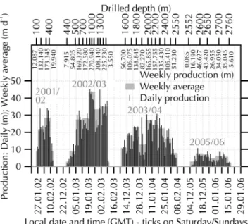
4.7. Core production
The slope of the penetration curve (Fig. 1) reflects the core production. Figure 11 presents the daily and weekly average production, as well as the weekly production. Table 1 lists the seasonal added core length. After the first season (2001/ 02), which involved a lot of setting-up time, we had obtained 337.512 m; the second (2002/03) and third (2003/04) seasons contributed 1112.980 and 999.570 m respectively. Production was increased initially by shifting to longer work hours after the whole team had been trained. The second season maintained full production until the end, while in the third season we had a less productive fourth week, where we paused some evenings of seasonal holidays. Towards the end of the third season, penetration became more difficult and we could not maintain full productivity towards the end of the season. We drilled frequently during the fourth season (2005/06), gaining 207.962 m added core length with the short-barrel version of the drill and, although we could maintain reasonable production, at some point productivity dropped to unacceptable levels. We then decided to use EWS to speed the core production rate, as our estimates indicated that we would not reach bedrock at the penetration rate we were achieving without EWS.
4.8. Core quality and length
Overall, core quality was good. This was facilitated by having a straight drill, sharp cutters and sharp core catchers. The main parameter related to our scientific analysis of the core, which we can analyse empirically, is the number of
Fig. 10. Plumbed liquid level. Date format is dd.mm.yy.
Table 2. Liquid balance
Season Total consumption Hole volume* Casing loss† In spun chips‡ Collected under winch drum§
Evaporation and spray¶
Drilling fluid consumption
D40 HCFC 141b Totaljj Corrected** m3 m3 m3 m3 m3 m3 m3 L m–1 L m–1 2001/02 6.00 1.70 4.92 0.99 0.24 1.55 22.8 19.9 2002/03 13.90 4.90 14.69 0.19 0.91 3.01 16.9 16.7 2003/04 10.50 5.60 13.24 0.42 0.65 1.40 0.39 14.7 14.3 2005/06 1.60 1.70 2.86 0.11 0.33 15.8 All 32.00 13.90 35.71 1.60 1.91 1.40 5.28 16.7 16.1 *Volume of the hole; for 2005/06 season also additional volume for upper bore reaming.
†Liquid filled higher than 81 m below top of casing and drained out between seasons. ‡
Computed from estimated weight increase 12.7% (2001/02), 14.4% (2002/03), 11.4% (2003/04), 9.5% (2005/06) multiplied by the gross chip recovery and divided by density.
§Liquid collection pan installed under the winch in 2003/04. 1.4 m3collected liquid was brought home as waste. In 2005/06 was reused. ¶Difference from other columns, lost into the air or the snow in the drill trench.
jjTotal consumption without collection under winch drum.
pieces (Fig. 12) we recorded after extraction of the core. Related to our aforementioned change in procedures (i.e. by not breaking the core and resuming penetration after initially obtaining penetration) the number of pieces should be low. The number of fragments mainly reflects the brittleness of the core, as a brittle core is more prone to breaking when pulling up the drill and handling it on the surface. We had three runs with fragmented ice in the barrel: 882, 925 and 986 m. It is not clear what happened during pull-up, but the core came to the surface shattered. We did not observe a severe ‘brittle zone’. However, the number of pieces per run reflects the brittle zone and we use the following observation to define it. During the first season (2001/02) we still employed the procedure whereby we broke the core during a run in the hope of resuming penetration, therefore we cannot use the number of pieces for this purpose. But, of course, we would not expect a brittle zone so near the surface. After only one core previously broken into three pieces, the first run below 450 m with six pieces was at �498 m depth, followed by more runs with even more pieces, up to and including the three aforementioned totally shattered runs. At 1050 m we
had one run with three pieces, after which we drilled nearly 600 m more with two pieces per run at most. Below this, drilling became more complicated again. We conclude that the core tended to be brittle between 500 and 1050 m.
Figure 13 presents the recorded core length, which is the length of the retrieved core in a single run. Figure 14 presents its distribution for the different seasons and for the entire operation. During the 2001/02 season the spread between short and long runs is greater than during the 2002/03 season when the maximal core length was slightly shorter but virtually no short runs were hauled. This is also expressed as an increased average core length. During the third (2003/04) season, drilling was more complicated: we could not regularly attain the maximal core length but instead had more medium to long runs. Even so, we avoided short runs, which characterized the drilling mode of the first season. The fourth (2005/06) season was marked by more arduous penetration and the use of a short version of the drill. That fourth season was characterized by a fairly constant core length, up to that short drill’s core-barrel length.
4.9. Piece length
Figure 15 presents the time-series variation of drilling-induced piece length, which is the difference between core break depths, within one run. If the operator breaks the core within one run, the shorter pieces will be reflected in these statistics. During the first season (2001/02), we had the
Fig. 12. Number of pieces. Date format is dd.mm.yy.
Fig. 13. Core length and use of EWS. Date format is dd.mm.yy.
Fig. 14. Core length distribution. Fig. 11. Daily and weekly average core production. Date format is
widest spread between short and long cores. Changing the drilling procedures during both the 2002/03 and 2003/04 seasons reduced the production of short core pieces in favour of the longest cores being somewhat shorter. During the fourth (2005/06) season, we employed a short version of the drill, so the statistics cannot be compared directly. We tried to obtain an integral measure characterizing the improved core quality (i.e. in terms of fewer, longer pieces). For the first three seasons, 63–64% of cores are longer than 1.75 m, but the proportion of short cores (<1 m) decreases from 33% to 26% and then to 22%. With the changed manner we avoided very short pieces, shifting those to the longer 1–1.75 m fraction.
4.10. Lessons for future work
During the later seasons, bad winch-spooling errors caused a build-up of ugly local piles of cable on the drum. On such occasions, we had to stop pulling up, unspool the cable down to the spooling error and then re-spool carefully. For the most part, spooling errors were initiated in the layer of cable immediately below the current layer, in which case the cable was not unspooled during a run; a small gap in that layer of cable was cut into by the now more tightly tensioned active layer. This resulted in the spooling irregu-larity, which was then compounded with each additional layer added during the lifting of the drill. We successfully filled such gaps by freezing-in water, and even employed slices of rubber to guide the cable into its correct position. Initially, we had incorrectly assumed that these spooling errors resulted from insufficiently high initial cable tension, so we went to the significant effort of re-spooling the cable with a friction winch at the beginning of the fourth season (2005/06). Finally, we realized that the bolts of the winch drum had become loose and it was �3 mm skew (i.e. not parallel). This is about half a cable diameter, and it was obvious that the cable could not possibly spool evenly under such conditions. Tightening the bolts with the cable on the drum solved the problem. We learnt that it is necessary to check the bolts on the drum, as well as the cable tension, in case spooling problems occur.
Assembling and maintaining electronics and mechanical drill components at the beginning of the seasons consumed a total of several weeks of field time. Our experience shows that it would be cheaper and more efficient if funding allowed deep Antarctic fieldwork to be better prepared, and if it allowed cancelling or delaying a season that requires better preparation back home.
5. DISCUSSION
The drill system discussed herein is the slightly modified one from NGRIP (Johnsen and others, 2007) and similar to that used at EDC (Augustin and others, 2007a). This paper highlights different working procedures and slight modifica-tions to the system we adopted during the EDML drilling operation. As different drill designs introduce ever greater degrees of freedom, which necessarily complicates the understanding of cause and effect, we discuss below our varied operational procedures across several seasons and in relation to the two above-mentioned sister drillings with comparable drill systems.
We observed excellent, 100% chip recovery due to closing of the openings at the lower end of the outer barrel, and to strictly limiting the permissible cable payout. Both measures reduce the likelihood of chips moving upward through the annulus between the outer barrel and the borehole wall. The drill exhibits much more resistance to advance if chips remain around the drill head. We experienced slightly decreased penetration speed due to these changes, but we could then operate the system in a stable mode wherein generated chips were removed from the hole immediately. That is to say, they did not accumulate in the fluid and did not have to be filter-bailed from time to time, so the slightly longer drilling times were traded off against less time for filter-bailing the bore. By limiting the permissible cable drop, our longest cores were somewhat shorter on average. On the other hand, we brought almost-full chip chambers to the surface at each run, and interpret this as evidence for operating the system in just the way it was envisaged to operate: the design objective had always been to collect all drilling chips as soon as they were generated.
The immediate and complete removal of chips from the hole is a prerequisite for stable drilling. Otherwise, with the densifier used, the chips tend to collect at the borehole bottom, where they stick to the drill head, resulting in poor or no penetration. The increased average core length (though at the expense of slightly shorter longest runs) during the second season reflects this. The number of lost runs (those with no penetration) was reduced. Simultan-eously, filling the drill with a long core but losing chips in the hole because the chip chamber is filled is also avoided by our new procedures. During the third season, drilling became more difficult, numerous reasons led to aborted runs and the average core length again decreased slightly.
After the first season, by limiting deliberate core-breaking during a run and controlling the allowable cable-weight drop, and cable payout, we decreased the fraction of short core pieces (the fraction of very long pieces was also reduced of course). In summary, we significantly increased core quality by preventing very short core pieces. We increased the fraction of pieces falling into the interval 1–1.75 m, while the fraction of pieces longer than 1.75 m remained constant. Achieving a stable, consistent penetration mode de-pended to a large extent on running at lower cutter pitch. This was generally possible, and when we approached the warmer part at the bottom of the glacier the drill head was arranged with a single cutter only, permitting us to run pitch as low as 1–2 mm. The single cutter resulted in having no more <0.5 m long cores. Compared with pressure-melting temperatures at NGRIP (5 K) and EDC (3.6 K), we were able to approach the pressure-melting point to within 3.1 K (Augustin and others, 2007b) at 2667 m drilled depth, when even that single-cutter arrangement failed to produce a core
length >0.5 m. The coarser chips produced with the one-cutter arrangement compared with three one-cutters may explain the enhanced performance. Those coarser chips have less surface area and are therefore less prone to adhesion of densifier and other effects that finally result in heating of the chips (Azuma and others, 2007). Proceeding in this manner allowed us to use much less EWS compared with the sister drillings, and improved the core and borehole quality.
The above-mentioned penetration problem arising at �2550 m (logging depth) at the end of the third season could be linked to changing grain size, which jumps from 1.073 mm measured in a sample from 2545.1 m, to 3.385 mm in a sample from 2596.1 m depth (Weikusat and others, 2009); there is no indication of a concomitant change in the fabric. We cannot pin the sudden change more precisely, as the sampling interval for thin-section observation is only that coarse.
The above-mentioned borehole closure below 2385 m logging depth coincides with the penultimate glacial tran-sition from MIS6 into MIS5.5 (Oerter and others, 2012, fig. 30). Due to the higher levels of impurities, the glacial ice from MIS6 is much softer compared with the interglacial ice from MIS5.5. Especially at high temperature (>260 K; Wilhelms and others, 2007) the strain rate increases drastically for a given differential stress, and so promotes borehole deformation or closure, which is also feasible as the hole seems to be slightly under-pressured.
We consistently determined the residual content of liquid in the chips in the range 10–14% and produced a detailed accounting of where the liquid finally went. We eliminated a significant source of loss from the dripping cable and, as a result, used <16 L m–1of drill fluid afterwards, significantly less drill liquid than our sister drillings (e.g. Augustin and others, 2007a; Talalay and others, 2014).
Hard and fast pulls carry the risk of wedging in the drill. Compared with the first season, we limited pulls to a preset range at which we determined cores would usually break, and thereafter did not experience any alarmingly hard pulling forces to break the core all the way down to 2500 m depth. Below that depth, the required pulling force in-creased again, most likely linked to the ice becoming more ductile at high temperature (Wilhelms and others, 2007).
6. CONCLUSIONS
Every deep-drilling operation has its own advantages and limitations, and of course we were able to carry out some aspects more efficiently than colleagues involved in earlier drilling operations with similar equipment. We benefited greatly from the experience they acquired and openly shared within the drilling community, which met on a regular basis during the period over which these different deep-drilling operations took place.
In terms of design, the intake for the chips at the bottom of the outer barrel needs attention, especially the openings. A feature to help the chips to move inside the drill and prevent them from moving into the outermost annulus is highly desirable. To ensure the chips move into the drill, we suggest setting the penetration speed based on strictly limiting the decrease of the drill’s load throughout a run as an operational measure.
We found a way to drive at very low pitch even in warm conditions. Many penetration problems at the EPICA and NGRIP sites were due to the unfavourable properties of the
HCFC densifiers. These densifiers adhere to the chips, allowing them to sink to the bottom of the hole or even aggravating the problem by spontaneous formation of HCFC clathrate (Murshed and others, 2007). With newer (e.g. ESTISOL™- and COASOL™-grade) liquids or n-butyl acetate this appears not to be a problem, so the prospect for future operations is much better in this respect.
It is generally known that the texture and fabric of the ice has a great impact on properties affecting cut ability. To provide more information on sources of drilling problems, it will be helpful to take texture and fabric samples routinely during the drilling operation, soon after the cores are on the surface, and to analyse them as quickly as possible so as to obtain better information on material-inherent reasons for bad penetration.
While EPICA drilling operations were ultimately highly successful, they were full of problems, all of which were managed thanks to the inherent spirit of cooperation and a highly motivated group of people. An important lesson is that if one is forced to engage in an operation with the same equipment in both hemispheres, even though at different times of the year, one will inevitably face additional problems. These resulted because no proper maintenance was possible between deployments due to long shipping times. Fixing of equipment in the field became necessary and that shortened the available drilling time during what were already short field seasons.
AUTHOR CONTRIBUTION STATEMENT
F.W. wrote the paper, H.M. wrote the section on the history of EPICA, M.D.G. edited the text, and all the authors contributed their ideas, endurance and commitment to retrieve this valuable ice core.
ACKNOWLEDGEMENTS
We thank Pavel Talalay and Olivier Alemany for careful reviews and valuable comments that improved the clarity of the paper. We thank the late Niels Gundestrup, Laurent Augustin, Heinrich Rufli and Jakob Schwander for continu-ing support when preparcontinu-ing the drillcontinu-ing seasons. We thank the logistic staff, particularly Jens Köhler, Holger Wohlt-mann, Ralf Witt, Günter Stoof, Adolf AckerWohlt-mann, Holger Schubert, Andreas Brehme, Jochen Krischat and Markus Weynand, for providing a reliable camp infrastructure. We thank Hans Oerter for pre-site surveying of the area, coordinating the preparation and implementation of the EPICA DML drilling project and for his valuable comments that improved the paper. Marzena Kaszmarska participated in the drill team. This work is a contribution to the European Project for Ice Coring in Antarctica (EPICA), a joint European Science Foundation/European Commission scientific pro-gramme, funded by the the European Union (EPICA-MIS) and by national contributions from Belgium, Denmark, France, Germany, Italy, the Netherlands, Norway, Sweden, Switzer-land and the United Kingdom. The main logistical support was provided by the French (IPEV) and Italian (PNRA) polar institutes (at Dome C) and AWI (at Dronning Maud Land).
REFERENCES
Augustin L and Antonelli A (2002) The EPICA deep drilling program. Mem. Natl Inst. Polar Res., Special Issue 56, 226–244
Augustin L, Panichi S and Frascati F (2007a) EPICA Dome C 2 drilling operations: performances, difficulties, results. Ann.
Glaciol., 47, 68–72 (doi: 10.3189/172756407786857767)
Augustin L and 6 others (2007b) Drilling comparison in ‘warm ice’ and drill design comparison. Ann. Glaciol., 47, 73–78 (doi: 10.3189/172756407786857820)
Azuma N, Tanabe I and Motoyama H (2007) Heat generated by cutting ice in deep ice-core drilling. Ann. Glaciol., 47, 61–67 (doi: 10.3189/172756407786857848)
Drücker C, Wilhelms F, Oerter H, Frenzel A, Gernandt H and Miller H (2002) Design, transport, construction. and operation of the summer base Kohnen for ice-core drilling in Dronning Maud Land, Antarctica. Mem. Natl Inst. Polar Res., Special Issue 56, 302–312
EPICA Community Members (2004) Eight glacial cycles from an Antarctic ice core. Nature, 429(6992), 623–628 (doi: 10.1038/ nature02599)
EPICA Community Members (2006) One-to-one coupling of glacial climate variability in Greenland and Antarctica. Nature,
444(7116), 195–198 (doi: 10.1038/nature05301)
Greenland Ice Core Project (GRIP) members (1993) Climate instability during the last interglacial period recorded in the GRIP ice core. Nature, 364(6434), 203–207 (doi: 10.1038/364203a0) Grootes PM, Stuiver M, White JWC, Johnsen S and Jouzel J (1993) Comparison of oxygen isotope records from the GISP2 and GRIP Greenland ice cores. Nature, 366(6455), 552–554 (doi: 10.1038/366552a0)
Gundestrup NS, Johnsen SJ and Reeh N (1984) ISTUK: a deep ice core drill system. CRREL Spec. Rep. 84-34, 7–19
Gundestrup NS, Clausen HB and Hansen BL (1994) The UCPH borehole logger. Mem. Natl Inst. Polar Res., Special Issue 49, 224–233
Gundestrup NS, Johnsen SJ, Hansen SB, Shoji H, Talalay P and Wilhelms F (2002) Sticking deep ice core drills. Why and how to recover. Mem. Natl Inst. Polar Res., Special Issue 56, 181–195 Johnsen SJ, Dansgaard W, Gundestrup N, Hansen SB, Nielsen JO and Reeh N (1980) A fast light-weight core drill. J. Glaciol.,
25(91), 169–174
Johnsen SJ, Gundestrup NS, Hansen SB, Schwander J and Rufli H (1994) The new improved version of the ISTUK ice core drill.
Mem. Natl Inst. Polar Res., Special Issue 49, 9–23
Johnsen SJ and 16 others (2007) The Hans Tausen drill: design, performance, further developments and some lessons learned.
Ann. Glaciol., 47, 89–98 (doi: 10.3189/172756407786857686)
Jouzel J (2013) A brief history of ice core science over the last 50 yr.
Climate, 9(6), 2525–2547 (doi: 10.5194/cp-9-2525-2013)
Murshed MM, Faria SH, Kuhs WF, Kipfstuhl S and Wilhelms F (2007) The role of hydrochlorofluorocarbon densifiers in the formation of clathrate hydrates in deep boreholes and subglacial environments. Ann. Glaciol., 47, 109–114 (doi: 10.3189/ 172756407786857659)
North Greenland Ice Core Project (NorthGRIP) Members (2004) High-resolution record of Northern Hemisphere climate extend-ing into the last interglacial period. Nature, 431(7005), 147–151 (doi: 10.1038/nature02805)
Oerter H, Drücker C, Kipfstuhl J and Wilhelms F (2012) Kohnen station – the drilling camp for the EPICA deep ice core in Dronning Maud Land. Polarforschung, 78(1–2), 1–23
Petit JR and 18 others (1999) Climate and atmospheric history of the past 420,000 years from the Vostok ice core, Antarctica. Nature,
399(6735), 429–436 (doi: 10.1038/20859)
Talalay PG (2013) Subglacial till and bedrock drilling. Cold Reg.
Sci. Technol., 86, 142–166 (doi: 10.1016/j.coldregions.2012.
08.009)
Talalay PG and Gundestrup NS (1999) Hole fluids for deep ice core
drilling: a review. University of Copenhagen, Copenhagen (doi:
10.2312/report_icedrill)
Talalay PG and Gundestrup NS (2002) Hole fluids for deep ice core drilling. Mem. Natl Inst. Polar Res., Special Issue 56, 148–170
Talalay P and 6 others (2014) Environmental considerations of low-temperature drilling fluids. Ann. Glaciol., 55(65), 31–40 (doi: 10.3189/2014AoG65A226)
Weikusat I, Kipfstuhl S, Faria SH, Azuma N and Miyamoto A (2009) Subgrain boundaries and related microstructural features in EDML (Antarctica) deep ice core. J. Glaciol., 55(191), 461–472 (doi: 10.3189/002214309788816614)
Wilhelms F, Sheldon SG, Hamann I and Kipfstuhl S (2007) Implications for and findings from deep ice core drillings – an example: the ultimate tensile strength of ice at high strain rates. In Kuhs WF ed. Physics and chemistry of ice. (Special Publication 311) Royal Society of Chemistry, Cambridge, 635–639