HAL Id: hal-00875413
https://hal-iogs.archives-ouvertes.fr/hal-00875413
Submitted on 22 Oct 2013
HAL is a multi-disciplinary open access
archive for the deposit and dissemination of sci-entific research documents, whether they are pub-lished or not. The documents may come from teaching and research institutions in France or abroad, or from public or private research centers.
L’archive ouverte pluridisciplinaire HAL, est destinée au dépôt et à la diffusion de documents scientifiques de niveau recherche, publiés ou non, émanant des établissements d’enseignement et de recherche français ou étrangers, des laboratoires publics ou privés.
X-ray-ultraviolet beam splitters for the Michelson
interferometer
Franck Delmotte, Marie-Françoise Ravet, Françoise Bridou, Françoise
Varniere, Philippe Zeitoun, Sébastien Hubert, Laurent Vanbostal, Gérard
Soullie
To cite this version:
Franck Delmotte, Marie-Françoise Ravet, Françoise Bridou, Françoise Varniere, Philippe Zeitoun, et al.. X-ray-ultraviolet beam splitters for the Michelson interferometer. Applied optics, Optical Society of America, 2002, 41 (28), pp.5905-5912. �10.1364/AO.41.005905�. �hal-00875413�
X-ray– ultraviolet beam splitters for the Michelson
interferometer
Franck Delmotte, Marie-Franc¸oise Ravet, Franc¸oise Bridou, Franc¸oise Varnie`re, Philippe Zeitoun, Se´bastien Hubert, Laurent Vanbostal, and Ge´rard Soullie
With the aim of realizing a Michelson interferometer working at 13.9 nm, we have developed a symmet-rical beam splitter with multilayers deposited on the front and back sides of a silicon nitride membrane. On the basis of the experimental optical properties of the membrane, simulations have been performed to define the multilayer structure that provides the highest reflectivity–transmission product. Opti-mized Mo–Si multilayers have been successfully deposited on both sides of the membrane by use of the ion-beam sputtering technique, with a thickness-period reproducibility of 0.1 nm. Measurements by means of synchrotron radiation at 13.9 nm and at an angle of 45° provide a reflectivity of 14.2% and a transmission of 15.2% for a 60% s-polarized light, close to the simulated values. Such a beam splitter has been used for x-ray laser Michelson interferometry at 13.9 nm. The first interferogram is discussed. © 2002 Optical Society of America
OCIS codes: 230.1360, 230.4170, 310.1860, 310.6860, 340.0340, 340.7450.
1. Introduction
Since their first realization around 15 years ago, x-ray transmissive optics permit new investigations in x-ray optics applications. Now x-ray optics tech-nology has evolved to the point at which it is possible to extend the applications field to x-ray– ultraviolet 共X–UV兲 interferometry with the objective to charac-terize optics or dense plasmas. Indeed, in the study of laser-produced plasmas, optical interferometry has played a key role in absolute measurements of elec-tron densities in a wide range of plasmas.1,2 But the
maximum electron density accessible and the size of the probed plasmas are severely restricted by absorp-tion and refracabsorp-tion of the probe beam. For these
reasons there has existed a need to develop inter-ferometers in the soft-x-ray range in which these ef-fects can be mitigated. A grating or a purely reflective x-ray interferometric system, such as the Fresnel bimirror setup, has been discussed in the literature and has been used successfully.3,4
How-ever, either technique lacks some of the advantages of standard interferometer geometries. In 1995 Da Silva and collaborators developed an amplitude-division x-ray Mach–Zehnder, successfully used to probe a dense plasma at 15.5 nm.5 This experiment
revealed internal residual stresses in X–UV beam splitters,6which induce fringe-pattern deformations
that can hamper the interpretation of plasmas’ inter-ferograms. So to reduce the fringe-pattern defor-mation, we chose to develop an X–UV Michelson interferometer consisting of only one beam splitter with its own internal stress operating at a 45° inci-dence angle at 13.9 nm.
Silicon nitride membranes have been widely used as a semitransparent substrate for x-ray transmis-sive optics in the wavelength range of 13–16 nm be-cause of their relatively high transmission.5,7,8
Indeed, to realize a beam splitter in the soft-x-ray range, one can either deposit a multilayer on a mem-brane or deposit a multilayer on a silicon nitride layer and then etch the substrate’s back side. In either case, the beam splitter can provide a good reflectivity from the coated side and a good transmission. Un-fortunately, the reflectivity from the uncoated side is
F. Delmotte共[email protected]兲, M.-F. Ravet, F. Bridou, and F. Varniere are with Groupe de Physique des Films Minces, Laboratoire Charles Fabry de l’Institut d’Optique, Centre National de la Recherche Scientifique, Unite´ Mixte de Recherche 8501, Centre Scientifique Baˆtiment 503, 91403 Orsay CEDEX, France. P. Zeitoun, S. Hubert, and L. Vanbostal are with Labora-toire de Spectroscopie Atomique et Ionique, Centre National de la Recherche Scientifique, Unite´ Mixte de Recherche 8624, Univer-site´ Paris-Sud, 91405 Orsay, France. G. Soullie is with Commis-sariat a l’Energie Atomique, BP 12, 91680, Bruye`res-le-Chaˆtel, France.
Received 2 January 2002; revised manuscript received 25 June 2002.
0003-6935兾02兾285905-08$15.00兾0 © 2002 Optical Society of America
low (typically less than 5%) owing to the absorption in the silicon nitride membrane before and after the reflection on the multilayer coating. Consequently, this kind of beam splitter is not suited for the Mich-elson interferometer, in which good reflectivities from both sides of the beam splitter are required to prevent contrast losses between the two arms of the inter-ferometer. One solution to this problem is to use free-standing multilayers as those described by Haga
et al.9 However, the development of such a beam
splitter is rather complex and involves many techno-logical steps, leading to a high cost.
As an alternative, we propose a symmetrical beam splitter with multilayers deposited on the front and back sides of a silicon nitride membrane. In this paper we describe the simulation, development, and wavelength calibration of this new kind of beam split-ter to be used in an X–UV Michelson insplit-terferomesplit-ter.
2. Experimental Technique
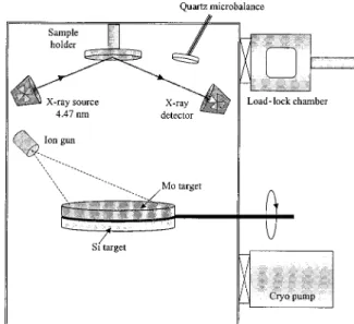
Multilayers are deposited by an ion-beam sputtering technique, in a ultrahigh-vacuum chamber cryo-pumped to a base pressure of less than 10⫺6Pa and equipped with a load-lock chamber 共Fig. 1兲. The 5-in.-diameter共1 in. ⫽ 2.54 cm兲 Mo and Si targets are successively ion beam sputtered by rotation of the target-holder system. We use a 3-cm Ion Tech ion-beam source with a mixture of 10% H2 in Ar gas.
Throughout the study, the ion-beam current and ion energy on the target are fixed at 30 mA and 650 eV, respectively. The samples are mounted on top of the chamber on a 2-in.-diameter sample holder. Depos-ited thicknesses are controlled by means of a quartz microbalance and an in situ x-ray reflectometer work-ing at 4.47 nm共Cu K␣兲. The combination of these two techniques provides good accuracy on the period thickness of the multilayer.
The specular x-ray reflectivity was measured ex
situ as a function of the incident angle with a
reflec-tometer working with the Cu K␣ emission 共 ⫽ 0.15405 nm兲 delivered by a classical x-ray tube, equipped with a graphite rear monochromator and 40-m entrance and reception slits. The angular resolution of the reflectometer is better than 0.001 deg. The reflectivity curve is obtained by our vary-ing the grazvary-ing angle while trackvary-ing the reflected beam. This kind of curve allows the determination of the parameters of the stack such as the complex indices, the thickness of each layer, and the interfa-cial roughnesses. After computation of theoretical reflectivities starting with given parameters, the ex-perimental reflectivity curve can be fitted by a trial-and-error method.10
An Akashi Topcon transmission electron micro-scope operated at 200 kV with a LaB6 filament was used for transmission electron microscopy 共TEM兲 studies. Cross-sectional specimens for TEM were mechanically polished to 80m and then dimpled in the center to 20m. This was followed by further thinning to electron transparency by Ar⫹-ion milling at 6 kV in a cooling stage.
Reflectivity and transmission measurements in the energy range of 65–150 eV have been performed at the Super ACO synchrotron facility共Orsay, France兲 on the SA23 beamline. The line is equipped with a 750-lines兾mm toroidal grating monochromator and a soft-x-ray reflectometer with an International Radi-ation Detectors, Inc. AXUV100 silicon diode as detec-tor. The monochromator resolution is approximately 0.7 eV at 100 eV and the degree of s polarization is approximately 60%.
3. Results and Discussion
A. Preliminary Study: Membrane Charaterization
In this study we use commercially available silicon nitride membranes provided by Silson Ltd. The sil-icon frame size is 10 mm ⫻ 10 mm, and the mem-brane size is 5 mm⫻ 5 mm. The Si3N4thickness is in the range of 80 –100 nm.
Silicon nitride membranes have been first charac-terized by x-ray grazing-angle reflectometry to deter-mine the thickness and the optical constant of Si3N4. The experimental data and the fit of these data are shown on Fig. 2. The fit gives a thickness of 88.5 nm and an index␦ of 9.6 ⫻ 10⫺6, i.e., approprimately 85% of the tabulated value for bulk Si3N4.
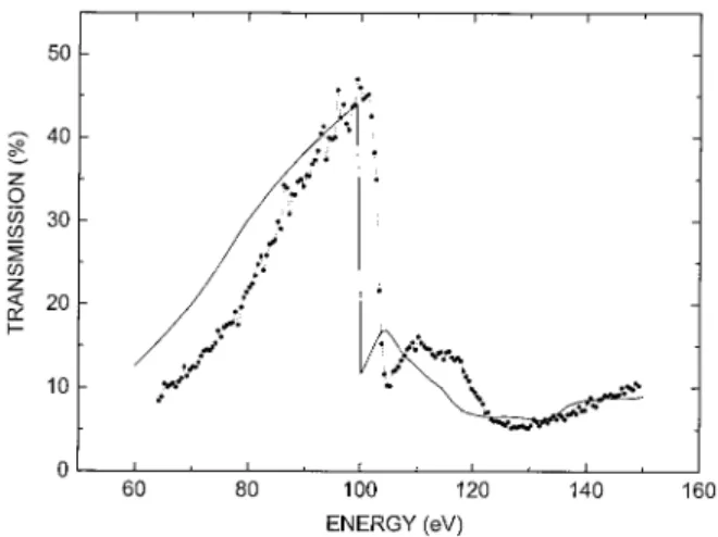
Figure 3 shows the transmission of the Si3N4
mem-brane measured at 45° in the 65–150-eV energy range. The high transmission at 89.2 eV共more than 35%兲 confirms that these membranes can be used as support for beam splitters. We have also plotted on Fig. 3 the simulated transmission of a single film of Si3N4, with a 88.5-nm thickness and a density of 2.92
g兾cm3共85% of the bulk Si
3N4density兲. We note an
energy shift in the Si absorption edge between sim-ulation and experimental data. This shift is approx-imately 3.4 eV and is interpreted as a consequence of the nature of chemical bonding in Si3N4, which is not taken into account in the simulation. Apart from this shift, the simulated curve is in good agreement
Fig. 1. Schematic diagram of the ultrahigh-vacuum deposition system.
with the experimental data, indicating that the pa-rameters chosen for the simulation are relevant. So we have decided to use this membrane model for the beam splitter simulations.
B. Optimization of the Beam Splitter Structure by Way of Simulation
In the wavelength range of interest for the x-ray laser interferometry applications 共around 13.9 nm兲, Mo and Si are common materials that present a good optical contrast, so we choose these materials to per-form the multilayer coating.
As explained in the introduction of this paper, we have developed a new kind of beam-splitter structure with multilayers deposited on the front and back sides of the silicon nitride membrane. The beam-splitter structure is shown in Fig. 4; we call it a “both-sides-coated Si3N4membrane.” Owing to the symmetry of this beam-splitter structure, the reflec-tivity from the back side should be the same as the
reflectivity from the front side. We have simulated this kind of beam splitter to optimize the relative thicknesses of Mo in the period共␥ ⫽ thMo兾thSi⫹ thMo兲
and the number of periods on each side 共NP兲. All
simulations were made in the case of s-polarized light under an incidence angle of 45° fixed by the inter-ferometer design. In fact, as the angle of incidence is the Brewster angle, the reflectivity for p polariza-tion is very low共typically, 100 times lower than for s polarization兲. So, when mounted in a Michelson in-terferometer, the beam splitter will be effective only for the s component of the x-ray source.
We have calculated the variation of the reflectivity–transmission product共R ⫻ T product兲 as a function of the relative thickness of Mo in the period with optimized NPfor each thickness and with a
pe-riod thickness of 10.2 nm. Results are optimized with ␥ values in the range of 0.2–0.3. Figure 5 shows the variation of the R⫻ T product as a function of the number of Mo–Si periods on each side with␥ fixed at 0.25: Approximately 3% of the R⫻ T prod-uct can be obtained with NPequal to 4 or 5.
On Fig. 6 we compare the reflectivities of a both-sides-coated共curve a兲 and a one-side-coated 共curves b and c兲 Si3N4membrane. In this latter case, we have
calculated the reflectivity from the coated side共curve b兲 and the reflectivity from the uncoated side 共curve c兲. For a both-sides-coated Si3N4membrane, the
re-Fig. 2. X-ray grazing-angle reflectometry curve measured at 0.154 nm on a silicon nitride membrane共circles兲 and fitted curve 共solid curve兲 obtained with a thickness of 88.5 nm and an index ␦ of 9.6⫻ 10⫺6for the silicon nitride. cps, counts per second.
Fig. 3. Transmission of the Si3N4membrane at 45° in the 65–
150-eV energy range: Circles represent the experimental values, and the solid curve is the simulated curve for a silicon nitride film with a 88.5-nm thickness and a density of 2.92 g兾cm3.
Fig. 4. Schematic diagram of a both-sides-coated silicon nitride membrane.
Fig. 5. Variation of the reflectivity–transmission product as a function of the number of Mo–Si periods on each side of the mem-brane. The relative thickness of Mo in the period共␥兲 was fixed at 0.25.
flectivity from the front and back sides would be the same owing to the symmetry of the beam-splitter structure. The oscillations that appear on the re-flectivity spectra a and c are due to the Fabry–Perot effect in the stack 共the Si3N4 membrane acts as a cavity兲. We also note that at the energy of interest 共89.2 eV for a wavelength of 13.9 nm兲, the both-sides-coated membrane presents a reflectivity of 25.8%, which is close to the reflectivity from the front side of the one-side-coated membrane 共28.4%兲 without the inconvenience of a very low reflectivity 共2.9%兲 from the back side. Calculations of the R ⫻ T product indicate an enhancement by a factor of 5 on the throughput by use of the both-sides-coated mem-brane. These results clearly show that the both-sides-coated Si3N4 membrane is well suited for
Michelson interferometry applications.
C. Fabrication of the Beam Splitter: Multilayer Deposition and Control
Before coating the Si3N4 membrane, we have to be sure of the quality and thicknesses of the deposited layers. For this study, we have deposited Mo–Si multilayers with Mo and Si thicknesses deduced from simulations on test samples共silicon or float glass sub-strates兲 with NP equal to 5. These samples were
first analyzed by grazing x-ray reflectometry at 0.154 nm.
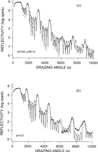
Figures 7共a兲 and 7共b兲 show the experimental curves and the fitted curves for two float glass substrates coated in the same conditions but not at the same time. The parameters determined by these fits are given in Tables 1 and 2, respectively. We note that the complex indices of Mo and Si layers at 0.154 nm are close to the tabulated ones11:
␦Si⫽ 7.6 ⫻ 10⫺6, ␦Mo⫽ 28.6 ⫻ 10⫺6,
Si⫽ 0.17 ⫻ 10⫺6, Mo⫽ 1.87 ⫻ 10⫺6.
These results suggest that deposited Mo and Si ma-terials are pure and dense. These fits also indicate
that the interfacial roughness estimated by x-ray re-flectometry is approximately 0.7 nm.
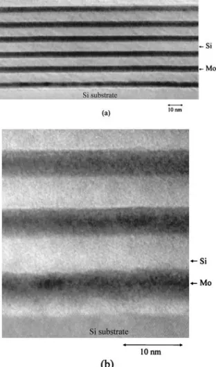
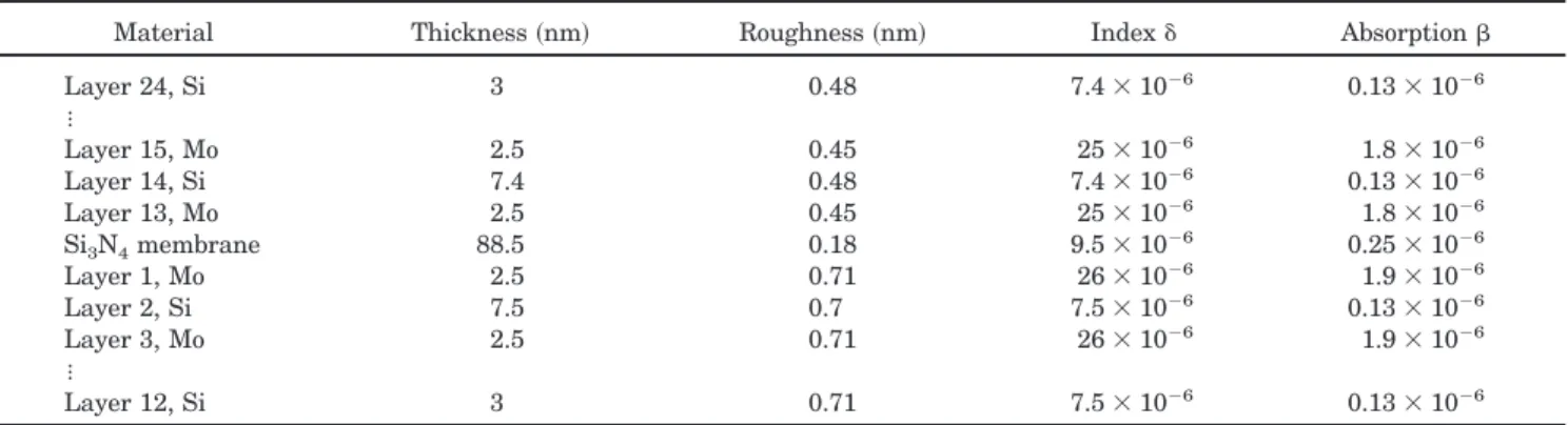
TEM and high-resolution TEM 共HRTEM兲 mea-surements are in good agreement with these results. The photographs shown in Figs. 8共a兲 and 8共b兲 reveal dense and continuous Mo and Si layers with well-defined interfacial regions. The interface between the first Mo layer and the Si substrate is rather rough probably owing to the oxide layer of the silicon sub-strate that had not been removed before deposition. The interfaces of the additional Mo layers are sharper and clearly show the effect of smoothening of the interfaces after only one period deposited. More-over, a high-resolution TEM analysis indicates that the Si and Mo layers are amorphous关Fig. 8共b兲兴. A polycrystalline structure of the Mo layers has often been reported in the literature in the case of magnetron-sputtering deposition.7,12–15 However,
the structure of Mo layers has been found to depend on the deposition method used, and amorphous Mo layers have been deposited by e-beam evaporation and ion-beam sputtering.12
One key for the success of the beam splitter is the
Fig. 6. Simulated reflectivities for a both-sides-coated Si3N4
membrane共curve a兲 and for a one-side-coated Si3N4membrane
with light coming on the coated side共curve b兲 or on the uncoated side共curve c兲.
Fig. 7. X-ray grazing-angle reflectometry curves: Experimental data measured at 0.154 nm on multilayer-coated float glass sample 共circles兲 and fitted curve 共solid curve兲. 共a兲 and 共b兲 correspond to two different samples deposited in the same condition but not at the same time.
reproductibility of the multilayer deposition on both sides of the membrane. The association of in situ reflectometry and in situ quartz microbalance allows us to control the thickness of the period within 0.1 nm between two depositions as illustrated in Figs. 7共a兲 and 7共b兲 and in Tables 1 and 2.
It is also essential to minimize the tensile stress in the beam splitter after the multilayer deposition 共ap-proximately 40 to 50 MPa兲.9,16 Ion-beam-deposited
multilayers are known to be highly stressed in a com-pressive mode: The stress of a Mo–Si multilayer similar to those used in the beam splitter 共with NP
equal to 5兲 has been calculated from the measure-ments of a Si substrate curvature before and after multilayer deposition by use of Stoney’s formula and is approximately⫺810 MPa. So we choose a highly tensile Si3N4 membrane: By varying the period thickness and number of period NP, we can adjust the
total stress value so that it remains in tensile mode. In the case of NP equal to 5, we found that beam
splitters wrinkle when the multilayer coating has a period thickness greater than 10.7 nm, whereas they remain flat when the period thickness is approxi-mately 10 nm. In the case of NPequal to 4, the beam
splitters remain flat whatever the period thickness is, in the range of 10 –10.7 nm.
D. Test and Calibration of the Beam Splitter
We have first measured grazing x-ray reflectivity of a both-sides-coated membrane at 0.154 nm to verify that the substrate nature 共i.e., the silicon nitride membrane兲 does not significantly modify the multi-layer quality. The measured data are shown on Fig. 9. The fit of these data is rather complex, so it has been made in two steps. First, we have determined the complex indices of materials by fitting the data coming from measurements on float glass witness samples that were coated at the same time as the
beam splitter 共one for each side兲. Then we have fixed the value of the complex indices, and we have fitted the data measured on the beam splitter by varying thicknesses and interfacial roughnesses. The fitted curve is shown on Fig. 9, and the results of this fit are given in Table 3. This result confirms that we have deposited very similar multilayers on both sides共period thickness of 9.9 and 10 nm兲 and indicates that the interfacial roughness in the multi-layers deposited on the membrane is not higher than those measured on float glass samples共Tables 1 and 2兲.
Beam splitters with NPequal to 4 and 5 have also
been tested on a synchrotron radiation source around the wavelength 13.9 nm 共89.2 eV in energy兲. All transmission and reflectivity measurements were made with an incidence angle of 45°. On Fig. 10共a兲 the transmission of a beam splitter with a NPof 4 and a period thickness of 10.7 nm is plotted as a function of x-ray energy. We note that two absorption edges appear on this curve: The first at approximately 100 eV is related to the absorption edge of silicon in the deposited layers, and the second at approximately 104 eV is related to the absorption edge of silicon in the silicon nitride layer, as reported on Fig. 3. The transmission value measured at 89 eV is 16.8% in this case. The reflectivity curve measured on the same beam splitter is plotted on Fig. 10共b兲. As pre-dicted by simulations, oscillations appear because of the Fabry–Perot effect in the Si3N4 membrane. At
89 eV the measured reflectivity is 10.5%. These re-sults show that, even with an unoptimized period thickness, this kind of beam splitter provides satis-fying transmission and reflectivity.
As expected, the reflectivity of a beam splitter with a NPof 5 and a period thickness of 10 nm is higher
and the transmission is somewhat lower: Measure-ments at 89 eV give 14.2% for reflectivity and 15.2%
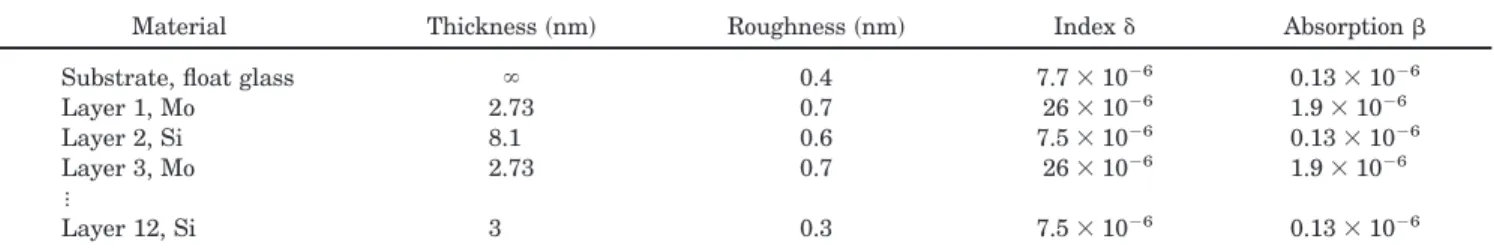
Table 1. Results of the Fit of an X-Ray Grazing-Angle Reflectometry Curve Measured on a Multilayer-Coated Float Glass Samplea
Material Thickness共nm兲 Roughness共nm兲 Index␦ Absorption Substrate, float glass ⬁ 0.4 7.7⫻ 10⫺6 0.13⫻ 10⫺6
Layer 1, Mo 2.73 0.7 26⫻ 10⫺6 1.9⫻ 10⫺6
Layer 2, Si 8.1 0.6 7.5⫻ 10⫺6 0.13⫻ 10⫺6
Layer 3, Mo 2.73 0.7 26⫻ 10⫺6 1.9⫻ 10⫺6
⯗
Layer 12, Si 3 0.3 7.5⫻ 10⫺6 0.13⫻ 10⫺6
aSee Fig. 7共a兲.
Table 2. Results of the Fit of an X-Ray Grazing-Angle Reflectometry Curve Measured on a Multilayer-Coated Float Glass Sampleb
Material Thickness共nm兲 Roughness共nm兲 Index␦ Absorption Substrate, float glass ⬁ 0.4 7.7⫻ 10⫺6 0.13⫻ 10⫺6
Layer 1, Mo 2.65 0.6 25⫻ 10⫺6 1.9⫻ 10⫺6 Layer 2, Si 8.1 0.35 7.4⫻ 10⫺6 0.13⫻ 10⫺6 Layer 3, Mo 2.65 0.6 25⫻ 10⫺6 1.9⫻ 10⫺6 ⯗ Layer 12, Si 3 0.3 7.4⫻ 10⫺6 0.13⫻ 10⫺6 bSee Fig. 7共b兲.
for transmission. From these values, and assuming a degree of s polarization of 60% on the synchrotron beamline that we have used, we can estimate that reflectivity and transmission for s-polarized x rays are, respectively, approximately 23% and 13%, which
means that the R⫻ T product is approximately 3% for this beam splitter. These values are very close to the predicted ones共see Figs. 5 and 6兲 and show that the deposition of high-quality multilayers on silicon nitride membrane has been achieved.
Finally, we have also measured the reflectivity of the back side of the beam splitter. On Fig. 11 we compare the reflectivity of the front side of a beam splitter to the reflectivity of the back side of another beam splitter deposited in the same conditions共NPof 5 and period thickness of 10 nm兲. Although the pe-riod thicknesses are quite the same, a shift appears in the Fabry–Perot oscillations. This shift could be in-terpreted either as a variation of the silicon nitride membrane thickness between the two beam splitters or as a variation of the relative thickness of Mo 共␥兲 between the two multilayers.
Figure 11 shows that the reflectivity of the back side is higher than the reflectivity of the front side 共26% against 20% if we compare the peak value兲. These features have already been reported by several authors8,9and have been related to the difference of
roughness of the silicon nitride membrane’s front side and back side 共the back side’s roughness is lower兲. Preliminary atomic force microscopy analysis have been done on both sides of our beam splitter and clearly show that the front side is much rougher than the back side. Further studies are in progress in order to know the real effect of this roughness on the beam-splitter performances and light polarization.
4. Conclusion
We have calculated and developed a new kind of X–UV beam splitter with symmetrical properties as required for an X–UV Michelson interferometer. Optimized Mo–Si multilayers have been successfully deposited on both sides of a commercially available silicon nitride membrane by use of the ion-beam sput-tering technique. The thickness-period reproduct-ibility is 0.1 nm and allows us to deposit similar multilayers on both sides of the membrane. Grazing x-rays reflectometry at 0.154 nm and TEM analysis show that the multilayers are made of dense, contin-uous, and amorphous Mo and Si layers. The inter-facial roughness estimated by x-ray reflectometry is approximately 0.7 nm and seems to be independent of the substrate type共float glass samples or silicon ni-tride membranes兲.
Synchrotron radiation measurements at 13.9 nm provide a reflectivity of 14.2% and a transmission of 15.2% for a 60% s-polarized light. From these mea-surements we can deduce that the R⫻ T product of the beam splitter is close to the simulated value of 3%. The reflectivity of the back side has been mea-sured to be somewhat higher than that of the front side. This phenomenon seems to be related to the roughness of the beamsplitter’s front side, which has been found to be higher than the roughness of the back side, as measured by atomic force microscopy.
Finally, these beam splitters have been used in a Michelson interferometer for an experiment devoted for the first time, to our knowledge, to Fourier
spec-Fig. 8. TEM and high-resolution TEM pictures of a Mo–Si mul-tilayer.
Fig. 9. X-ray grazing-angle reflectivity curves: experimental data measured on a both-sides-coated membrane at 0.154 nm 共cir-cles兲 and fitted curve 共solid curve兲.
troscopy linewidth measurement of a Ni-like silver soft-x-ray laser source operating at 13.9 nm by Fou-rier spectroscopy.17 As shown on Fig. 12, the
inter-ferogram obtained with a no-difference path between the two arms presents a contrast ranging from 76% to 92%, over the whole aperture of the beam splitter共5 mm⫻ 5 mm兲. However, we note that large defor-mations of fringes arise from residual stresses both in the Si3N4 membrane and in the Mo–Si multilayer
Table 3. Results of the Fit of an X-Ray Grazing-Angle Reflectometry Curve Measured on a Both-Side-Coated Silicon Nitride Membranea,b
Material Thickness共nm兲 Roughness共nm兲 Index␦ Absorption
Layer 24, Si 3 0.48 7.4⫻ 10⫺6 0.13⫻ 10⫺6 ⯗ Layer 15, Mo 2.5 0.45 25⫻ 10⫺6 1.8⫻ 10⫺6 Layer 14, Si 7.4 0.48 7.4⫻ 10⫺6 0.13⫻ 10⫺6 Layer 13, Mo 2.5 0.45 25⫻ 10⫺6 1.8⫻ 10⫺6 Si3N4membrane 88.5 0.18 9.5⫻ 10⫺6 0.25⫻ 10⫺6 Layer 1, Mo 2.5 0.71 26⫻ 10⫺6 1.9⫻ 10⫺6 Layer 2, Si 7.5 0.7 7.5⫻ 10⫺6 0.13⫻ 10⫺6 Layer 3, Mo 2.5 0.71 26⫻ 10⫺6 1.9⫻ 10⫺6 ⯗ Layer 12, Si 3 0.71 7.5⫻ 10⫺6 0.13⫻ 10⫺6 aSee Fig. 9.
bLayers 1 to 12 are on the front side, and layers 13 to 24 are on the back side of the silicon nitride membrane.
Fig. 10. Experimental transmission共a兲 and reflectivity 共b兲 mea-sured on a both-sides-coated membrane versus x-ray energy. X rays were coming on the front side. The angle of incidence was 45° and the degree of s polarization was approximately 60%. The multilayers have four periods and a period thickness of 10.7 nm.
Fig. 11. Experimental reflectivities measured on two both-sides-coated membranes versus x-ray energy, with x rays coming on the front side共circles兲 and on the back side 共triangles兲. The angle of incidence was 45°, and the degree of s polarization was approxi-mately 60%. The multilayers have five periods and a period thickness of 10 nm.
Fig. 12. Interferogram共screen shot兲 recorded at 13.9 nm with the Michelson interferometer with a zero-difference path difference.
coating. To prevent this kind of fringe-pattern de-formation, we are performing further studies to im-prove the x-ray beam splitter’s flatness.
The authors thank Philippe Troussel from Com-missariat a l’Energie Atomique, Bruye`res-le-Chaˆtel for the access to the reflectometer of the SA23 beam-line at the Laboratoire pour l’Utilisation du Rayonne-ment Electromagne´tique, Orsay. Financial support for this work was partially provided by the Centre National de la Recherche Scientifique program Trait-ement de surfaces et de´poˆt de couches minces.
References
1. G. Charatis, G. E. Busch, C. L. Shepard, P. M. Campbell, and M. D. Rosen, “Hydrodynamic aspects of selenium x-ray laser targets,” J. Phys. C 6, 89 –98共1986兲.
2. M. K. Prasad, K. G. Estabrook, J. A. Harte, R. S. Craxton, R. A. Bosch, G. E. Busch, and J. S. Kollin, “Holographic interfero-grams from laser fusion code simulations,” Phys. Fluids B 4, 1569 –1575共1992兲.
3. S. Chakrabarti, D. M. Cotton, J. S. Vickers, and B. C. Bush, “Self-compensating, all-reflection interferometer,” Appl. Opt.
33, 2596 –2602共1994兲.
4. J. Svatos, D. Joyeux, D. Phalippou, and F. Polack, “Soft-x-ray interferometer for measuring the refractive index of materi-als,” Opt. Lett. 18, 1367–1369共1993兲.
5. L. B. Da Silva, T. W. Barbee, Jr., R. Cauble, P. Celliers, D. Ciarlo, S. Libby, R. A. London, D. Matthews, S. Mrowka, J. C. Moreno, D. Ress, J. E. Trebes, A. S. Wan, and F. Weber, “Elec-tron density measurements of high density plasmas using soft X-ray laser interferometry,” Phys. Rev. Lett. 74, 3991–3994 共1995兲.
6. P. Celliers, F. Weber, L. B. Da Silva, T. W. Barbee, Jr., R. Cauble, A. S. Wan, and J. C. Moreno, “Fringe formation and coherence of a soft-x-ray laser beam illuminating a Mach– Zehnder interferometer,” Opt. Lett. 20, 1907–1909共1995兲. 7. D. G. Stearns, N. M. Ceglio, A. M. Hawryluk, M. B. Stearns,
A. K. Petford-Long, C. H. Chang, K. Danzmann, M. Kuhne, P. Muller, and B. Wende, “TEM and X-ray analysis of multilayer mirrors and beamsplitters,” in Multilayer Structures and
Lab-oratory X-Ray Laser Research, N. M. Ceglio and P. Dhez, eds.,
Proc. SPIE 688, 91–98共1987兲.
8. N. M. Ceglio, “Revolution in X-ray optics,” J. X-Ray Sci. Tech-nol. 1, 7–78共1989兲.
9. T. Haga, M. C. K. Tinene, A. Ozawa, Y. Utsumi, S. Itabashi, T. Ohkubo, and M. Shimada, “Fabrication of semitransparent multilayer polarizer and its application to soft x-ray ellipsom-eter,” in Ultraviolet and X-Ray Detection, Spectroscopy, and
Polarimetry III, S. Fineschi, B. E. Woodgate, and R. A. Kimble,
eds., Proc. SPIE 3764, 13–27共1999兲.
10. F. Bridou and B. Pardo, “Automatic characterization of layers stacks from reflectivity measurements. Application to the study of the validity conditions of the grazing X-rays reflecto-metry,” J. Opt.共Paris兲 21, 183–191 共1990兲.
11. B. L. Henke, E. M. Gullikson, and J. C. Davis, “X-ray interac-tions: photoabsorption, scattering, transmission, and reflec-tion at E⫽ 50-30000 eV, Z ⫽ 1-92,” At. Data Nucl. Data Tables
54, 181–342共1993兲 or http:兾兾www-cxro.lbl.gov.
12. S. Ogura, M. Niibe, Y. Watanabe, M. Hayashida, and T. Iizuka, “Comparison among multilayer soft X-ray mirrors fabricated by electron beam, DC-, RF-magnetron sputtering and ion beam sputtering deposition,” in X-Ray Multilayers for
Diffrac-tometers, Monochromators, and Spectrometers, F. E.
Chris-tensen, ed., Proc. SPIE 984, 140 –148共1988兲.
13. T. W. Barbee, J. C. Rife, W. R. Hunter, M. P. Kowalski, R. G. Cruddace, and J. F. Seely, “Long-term stability of a Mo兾Si multilayer structure,” Appl. Opt. 32, 4852– 4854共1993兲. 14. K. Holloway, K. Ba Do, and R. Sinclair, “Interfacial reactions
on annealing molybdenum-silicon multilayers,” J. Appl. Phys.
65, 474 – 80共1989兲.
15. D. G. Steams, R. S. Rosen, and S. P. Vernon, “Fabrication of high-reflectance Mo-Si multilayer mirrors by planar-magnetron sputtering,” J. Vac. Sci. Technol. A 9, 2662–2669 共1991兲.
16. C. Khan-Malek, J. Susini, A. Madouri, M. Ouahabi, R. Rivoira, F. R. Ladan, Y. Lepetre, and R. Barchewitz, “Semitransparent soft X-ray multilayer mirrors,” Opt. Eng. 29, 597– 602共1990兲. 17. S. Hubert, Ph. Zeitoun, E´ . Be´chir, D. Benredjem, F. Bridou, A. Calisti, F. Delmotte, M. Idir, G. de Lache`ze-Murel, S. Le Pape, M. F. Ravet, D. Ros, L. Vanbostal, and S. Hubert, “Line shape measurement of a Ni-like silver X-ray laser by mean of soft X-ray Fourier-transform spectroscopy,” submitted to Phys. Rev. A.