HAL Id: hal-02608221
https://hal.inrae.fr/hal-02608221
Submitted on 16 May 2020
HAL is a multi-disciplinary open access
archive for the deposit and dissemination of
sci-entific research documents, whether they are
pub-lished or not. The documents may come from
teaching and research institutions in France or
abroad, or from public or private research centers.
L’archive ouverte pluridisciplinaire HAL, est
destinée au dépôt et à la diffusion de documents
scientifiques de niveau recherche, publiés ou non,
émanant des établissements d’enseignement et de
recherche français ou étrangers, des laboratoires
publics ou privés.
An improved image processing method for particle
characterization by shadowgraphy
H. Wang, F. Felis, S. Tomas, Fabien Anselmet, M. Amielh
To cite this version:
H. Wang, F. Felis, S. Tomas, Fabien Anselmet, M. Amielh. An improved image processing method
for particle characterization by shadowgraphy. ILASS-Europe 2017 28th Conference on Liquid
Atom-ization and Spray Systems, Sep 2017, Valencia, Spain. pp.6, �10.4995/ILASS2017.2017.4614�.
�hal-02608221�
An Improved Image Processing Method for Particle
Characterization by Shadowgraphy
Hua Wang*
1, Francisco Felis
2, 3, Severine Tomas
2, Fabien Anselmet
3and Muriel Amielh
3 1Dantec Dynamics A/S, Skovlund, Denmark
2
Institut national de recherche en sciences et technologies pour l'environnement et
l'agriculture (IRSTEA), UMR G-EAU France
3
Institut de Recherche sur les Phenomenes Hors Equilibre (IRPHE), France
*Corresponding author: [email protected]
Abstract
Shadowgraphy is one of the most popular imaging techniques to characterize moving particles by their size, geometry as well as velocity, due to its simplicity. However, it requires advanced image processing to handle various image defects such as non-uniform illumination, overlapped particles, etc., which are normally only solved for individual applications. This study proposes a robust image processing method for particle shadowgraphy, aiming to process imperfect particle shadow images. The proposed method first detects qualified particles from particle shadow images, and then processes detected particles individually. Therefore different defects from different particles can be handled separately and locally. An overlapped particles detection and separation algorithm is also implemented to improve the accuracy of size and geometry characterization.
The proposed method is first proved by synthetic generated particle shadow images, followed by a proof test with shadow images from a transparent dot pattern target. Finally this method is successfully applied to a shadow image acquired from a water spray and proved to be able to handle various issues of shadowgraphy.
Keywords
Shadowgraphy, image processing, particle characterization
Introduction
Over past few years, there has been a growing interest and also increasing availability of commercial image analysis software for atomization characterization by means of shadowgraphy for spherical as well as irregular shape particles. Compared with point measurement techniques such as phase Doppler anemometry, it is easy to setup and the results are more straightforward to understand. Additionally, it can be applied for particles with any shape [1, 2] and it is not affected by multi-scattering effects [3, 4].
However, most of imaging process methods for shadowgraphy are made for individual applications and often demand high image quality [5], which cannot be achieved in many cases due to the complexity of the spray or the limitation from optical access. In general, these image processing methods are facing various challenges like too many droplets with various shapes in the field of view – which results in overlapped particles [6] or out-of-focus particles, non-uniform illumination, etc.
In this study, an advanced shadowgraphy image processing method is proposed to handle shadow images from complex sprays. The principle of this method will be firstly introduced, followed by verification from synthetic images, dot target images with known dot sizes, and then a validation with shadow images from a real spray.
Principle of shadow image processing
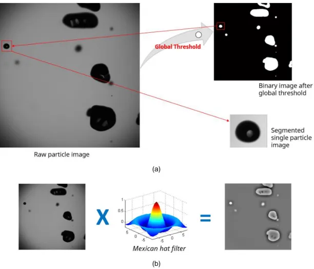
This method firstly detects particles based on a global threshold determined by the users – which depends on individual measurement. Optionally, a 2D Mexican hat filter can be applied to convolute the raw image and consequently a map of intensity gradient can be obtained, which indicates the edge of each particle. This procedure is proved to be more effective to detect particles when the back illumination is not uniform and the particles are out of focus [7]. Then each particle is segmented from the global image (gradient image in the case of optional filtering) with a bounding box which is slightly larger than itself for further process. This process is shown in Figure 1. Then, the particle segmentation is performed from this gradient image.
ILASS – Europe 2017, 6-8 Sep. 2017, Valencia, Spain
This work is licensed under a Creative Commons 4.0 International License (CC BY-NC-ND 4.0).
(a)
(b)
Figure 1. Particle detection and segmentation: (a) general routine, (b) Optional Mexican hat filter to be used instead of global
threshold
After the particle is segmented from raw image, a local threshold will be applied to the bounding box to extract the particle. The local threshold is calculated by:
𝑇ℎ𝑟𝑒𝑠ℎ𝑜𝑙𝑑𝑙𝑜𝑐𝑎𝑙= 𝑖𝑚𝑖𝑛+ (𝑖𝑚𝑎𝑥− 𝑖𝑚𝑖𝑛) ∗ 0.61 (1)
Where imin and imax are the minimal and maximum gray values in the segmented single particle image. The factor
of 0.61 is proposed by [8]. This value is the one which allows obtaining, based on point spread function, a polynomial relationship between contrast of particle image and measured particle diameter. Consequently, there is a potential to correct the measured size of those out-of-focus particles or to define a depth-of-field thickness where all particles are focused. None of these solutions is presently implemented in our algorithm.
Segmented single particle image uses this threshold to be binarized and particle will be extracted for further geometry characterization. By using a local threshold for each detected particle, the issues coming from non-uniform back illumination can be minimized. In addition, using a fixed factor to determine local threshold for particle diameter evaluation can also avoid subjectivity introduced from different users. More specifically, global threshold selected by the user would only affect the identification of particles – number of particles identified; once the particle is identified, its size only depends on the local threshold calculated from formula (1).
After the particle extraction, its diameter and other geometry information will be calculated by standard geometry characterization functions from OpenCV.
After geometry characterization, three validation methods can be applied if necessary: a) Particle area (range).
b) Particle eccentricity, which is defined as the ratio between the long axis and short axis.
c) Particle roundness, also called as inertia moment, which measures the spread of points around the centre of mass. Its definition is given by the formula below:
𝑛𝑢𝑗𝑖= 𝑚𝑢𝑗𝑖 𝑚00 𝑖+𝑗 2 +1 (3) 𝑚𝑢𝑗𝑖= ∑𝑥,𝑦(𝑥 − 𝑥̅)𝑗∙ (𝑦 − 𝑦̅)𝑖 (4)
Where x and y are coordinates of pixels within the particle, 𝑥̅ and 𝑦̅ are the centroid coordinates of the particle. All the three validations above are aiming to reject noise caused by dirt in the imaging system, which are often very small in the field of view and have different shapes from expected particles.
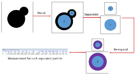
In addition, a method to detect and separate overlapped particles is also implemented here. This method assumes that overlapped particles (seen in Figure 2) can be separated into two (or more) smaller particles by shrinking from its boundary, which represents the kernels of those overlapped particles. If two (or more) smaller particles can be identified after shrinking, these particles will be identified as overlapped particles, and a expand process will be applied to those kernels to calculate the size of each separated particle. The amount of re-expand is identical as the amount of shrink. The process is described in Figure 2.
Figure 2. Method to detect and correct overlapped particles
This overlapped particles detection and correction is based on the assumption mentioned above. In some applications, particles shape can be highly irregular and therefore they are identified as overlapped particles. In this case, the proposed method is no longer suitable.
Results and discussion
The proposed shadow image processing method has firstly been evaluated by synthetic particle image, which is shown in Figure 3, together with the contour provided by shadow image processing. The synthetic particle image is a binary image made from Microsoft Paint program, with particles having diameters from 10 to 80 pixels. The diameter results provided by shadow image processing are given in Table 1.
ILASS – Europe 2017, 6-8 Sep. 2017, Valencia, Spain
This work is licensed under a Creative Commons 4.0 International License (CC BY-NC-ND 4.0).
Table 1. Comparison of the ground truth and diameter measured by shadow processing on the synthetic particles image
Ground truth (pix) Diameter measured by shadow processing (pix)
10 9.933 20 19.93 30 29.821 40 39.960 50 49.861 60 59.869 70 69.901 80 79.869
The comparison between measured diameter from shadow processing and ground truth shows a very good agreement between each other. This proves the accuracy of particle edge detection and diameter evaluation. The overlapped particles detection and separation is also firstly tested by synthetic particles image. The left side of Figure 4 shows a group of synthetic particles with slight overlapping and the right side of the same figure shows the particle contour given by shadow processing. Overlapped particles have been well detected and recovered by this method. This method has been also tested by synthetic particles images with severe overlapping but it failed to identify the overlapping.
Figure 4. Left, synthetic overlapped particles; Right, contour of each particle detected by shadow image processing
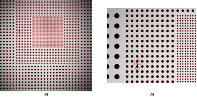
The next test has been carried out with a shadow image from a transparent target with dots pattern (Thorlabs R3L3S4P2), which is shown in Figure 5. The dots on this target have five different size groups but only three of them are shown in the field of view: 62.5 μm, 125 μm and 250 μm. The back illumination is slightly non-uniform to increase the challenges for the shadow processing. The scale in the image is 7.2 μm per pixel.
(a) (b)
Figure 5. (a) Shadow image of a transparent dot target, with three groups of dots (62.5 μm, 125 μm and 250 μm). Contour of
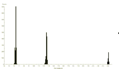
Figure 6. Diameter histogram of transparent dot target shadow image provided by shadow image processing Table 2. Summary of measurement results from shadow imaging processing on the transparent dot target shadow image
Dot Size (μm) Number of Dots Dots detected Average size measured by shadow processing
(μm)
Standard deviation of size measured by shadow
processing (μm)
62.5 1681 1681 63.98 0.92
125 1240 1239 127.75 1.08
250 400 371 255.73 0.90
Figure 6 shows the diameter histogram from shadow image processing, which indicates a very narrow distribution of each size group. Table 2 shows the comparison of target specifications and the results measured from shadow processing, which also shows a very good agreement. All small dots and middle dots are detected except only one middle dot which is missed because it is connected to a dirt on the target (shown in Figure 5.b). The missed big dots from shadow processing are due to the fact that they are very close to the frame border and are therefore rejected.
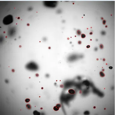
Different global thresholds have been also tested to study the influence of this parameter. Tests with various global thresholds show very similar result (variance < 1%). The slight difference is introduced by different numbers of particles identified with different global thresholds and therefore the statistical results are changed. Finally the proposed method has been tested with a shadow image acquired from a water spray, which is shown in Figure 7, together with the contour determined by shadow image processing. Typical challenges of shadow measurements on water spray can be all identified here, such as non-spherical particles, out-of-focus particles, overlapped particles, non-uniform back illumination, and so on.
Most of the particles can be detected and segmented correctly from this image with the proposed method. Particularly, that in the right bottom side (on top of a big out-of-focus particle) has been correctly detected. In addition, the two overlapped particles next to this big out-of-focus particle have also been detected and separated correctly. There are several sharp particles which are not identified, but this is because they are close to the image boundary and therefore are rejected.
ILASS – Europe 2017, 6-8 Sep. 2017, Valencia, Spain
This work is licensed under a Creative Commons 4.0 International License (CC BY-NC-ND 4.0).
Figure 7. Shadow images acquired from a water spray, together with red contour of each detected particle given by shadow
image processing
Several out-of-focus particles are also detected, which can cause a bias on the size result. Correction to these out-of-focus particles is not included in this study. Fdida and Blaisot proposed a method to correct the out-of-focus particles or to define a depth-of-field thickness where all particles are focused, based on the point spread function [8]. These methods will be implemented and investigated in the next stage of this project.
Conclusions
A new shadow processing method is proposed with advanced particle detection and segmentation algorithm, together with an overlapping particles detection and separation method. This method is firstly qualified by synthetic particle images and then further evaluated with shadow images of a transparent target with dot patterns. Later the new method is applied to shadow images from a water spray.
All test results show that this new shadow processing method can handle various issues of shadowgraphy measurement on water sprays. Particularly, this method is robust and less sensitive to parameters compared with existing shadow processing methods. In addition, this method can handle overlapped particles in the shadow image and provide more accurate results.
Acknowledgements
This work is supported by a collaboration project among IRSTEA, IRPHE and Dantec Dynamics A/S, aiming to improve characterization of moving irregular particles by shadowgraphy measurements.
References
[1] Bachalo, W. and Sankar. S., 2003, Spray diagnostics. In: Mercer, C.R. (Ed.). Optical Metrology for Fluids, Chap 5, Combustion and Solids. Springer-Verlag.
[2] Tropea, C., 2011, Annual Review Fluids Mechanics, 43, pp. 399–426.
[3] Lecuona, A., Rodriguez, P., Sosa, P., and Zequeira, R., 2000, Measurement Science and Technology, 11 (8), pp. 1152–1161.
[4] Ghaemia, S., Rahimib, P. and Nobesc, D., 2010, International Journal of Spray and Combustion Dynamics, 2 (2), pp. 103–124.
[5] Stevenin C., Tomas, S., Vallet, A., Amielh, M. and Anselmet, F., 2016, International Journal of Multiphase Flow, 84, pp. 264–278.
[6] Blaisot, J. and Yon, J., 2005, Experemental Fluids, 39 (6), pp. 977–994. [7] Yon, J., 2003, Doctoral thesis, University of Rouen.