Development of a Simplified Negative Pressure Wound Device
ByDanielle R. Zurovcik
B.S. Mechanical Engineering, 2004 Pennsylvania State University
Submitted to the Department of Mechanical Engineering in Partial Fulfillment of the Requirements for the Degree of
Master of Science in Mechanical Engineering at the
Massachusetts Institute of Technology June 2007
C2007 Danielle R. Zurovcik. All rights reserved.
The author hereby grants to MIT permission to reproduce and to distribute publicly paper and electronic copies of this thesis document in whole or in part.
Signature of Author:
Department of Mechanical Engineering May 21, 2007
Certified by: _
Alexar - . Slocum
Professor of Mechanical Engineering Thesis Supervisor
Accepted by:
MASSACIc-usrS INrSTUT
;{
TcHN~oo3
Lallit Anand Professor of Mechanical Engineering Chairman, Committee on Graduate Students
Development of a simplified Negative Pressure Wound Therapy Device
By
Danielle R. Zurovcik
Submitted to the Department of Mechanical Engineering on May 21, 2007 in partial fulfillment of the requirements for the
Degree of Master of Science in Mechanical Engineering
ABSTRACT
Many medical techniques are not readily available in the third world, in the military, for disaster relief, and in domestic environments. This can be due to a lack of electricity, high cost, and other economical constraints. For these reasons, a successful, chronic wound treatment, known as negative pressure wound therapy (NPWT), has not been readily used, although many patients would benefit. Aiming to expand this therapy, the viability of inexpensive, purely mechanical simplified negative pressure wound therapy (sNPWT) systems is explored in this thesis. Air leaks into the NPWT system are identified as the limiting factor for the possibility of sNPWT. An air leak detection system, along with proper dressing techniques, is defined.
Once sNPWT is proven to be viable, it is developed further, based on customer needs in the targeted markets and sNPWT functional parameters. Three vacuum pump embodiments are prototyped and analyzed for possible implementation: bellows pumps, bladder pumps, and rolling diaphragm pumps. The bellows pump is chosen for the final design, and is analyzed in preparation for manufacture. Once manufactured, the bellows pump will be used in clinical trials at the Shriners Bum Hospital in Boston, Massachusetts, under the guidance of Dr. Robert Sheridan.
Thesis Supervisor: Alexander Slocum Title: Professor of Mechanical Engineering
Acknowledgements
Reflecting on my graduate experience, there are many people to thank for where I stand today. Foremost, I would like to thank my mentor and advisor,
Professor Alexander Slocum. With his enthusiasm and motivation, I pursue my goals, while continuously learning from his wealth of knowledge. He inspires me to achieve new levels of intelligence and to embrace a love for design.
I would like to thank the Center for Integration of Medicine and Innovative
Technology (CIMIT) for sponsoring Professor Alexander Slocum's Precision Machine Design course and the initial work of this project. Their continued interest in the success of this project has widened its impact in the medical community. Particularly,
Dr. Jonathan Rosen and Dr. Kristian Olson have introduced me to many great opportunities.
Dr. Robert Sheridan has been the backbone of the project. Without his brilliance in medicine and dedication to his patients, this project would not exist. I am honored and proud to bring his idea for sNPWT to life. Brenden Epps, Kevin Lin, and Richard Timm played an initial role in this project during the Precision Machine Design course. Their enthusiasm and dedication also helped to bring this project to life.
I greatly appreciate Alison Hynd and the MIT IDEAS Competition for their devotion
towards innovation at MIT. In particular, I would like to thank ita Software for sponsoring the $5K IDEAS Award that has funded the second phase of the design research for this project.
Chad Foster has played a key role in the motivation and success of this project, and in my career at MIT. He has been on the project team for both the MIT IDEAS Competition
and the MIT $I OOK Competition, providing his thorough understanding of technical details.
I would like to thank all of the members of the Precision Engineering Research Group
(PERG) for welcoming me into the lab and providing their sound advice. In particular, I would like to thank Nevan Hanumara, John Hart, Melissa Read, A Trimble, Conor Walsh, Alexis Weber, and Onnik Yaglioglu for being a great group of coworkers and friends to share a lab with. I have learned a lot by sitting with such a diverse group of brilliant minds.
Additionally, I would like to thank Maureen Lynch for all of her hard work, and for helping me to find volunteers for my experiments.
The Robust Group at MIT was a great lab that I was initially a part of at MIT. Thank you to Professor Daniel Frey for advising me during that time and to Mr. Pappalardo for funding my initial research. I continue to expand on my initial work when I find time, as it continues to spark my interest. Additionally, Chad Foster, Xiang Li, Yiben Lin, Jagmeet
Singh, and Nandan Sudarsanam greatly impacted my education and experience at MIT. I continue to value their friendship and advice; their wisdom is amazing.
Friendships that I have made at MIT are priceless and will last a lifetime. It is impossible to thank everyone that I have befriended and shared many memories with; however, I must particularly thank the other two members of the "MIT Three Musketeers:" Jeff Chambers and Chris Pangilinan. It is very rare to meet friends as loyal as them. They have helped with this project in many ways, including peer review.
Last, but certainly not least, I would like to thank my family: my Dad,
Andrew J. Zurovcik, my Mom, Patricia Zurovcik, and my brother, Andrew M. Zurovcik. They inspire me to achieve great successes throughout the future. My Dad is always there to bounce ideas off of, and to provide an honest opinion, and my Mom always provides sound advice and dedication. They are the most wonderful parents.
Table of Contents
List of Figures... 9 List of Tables ... 13 Nom enclature... 15 1 Introduction... 17 1.1 Project Background ... 17 1.2 Current Study ... 18 2 Background... 23 2.1 H istory of NPW T ... 23 2.2 Proof of NPW T ... 26 2.2.1 Scientific Theory ... 26 2.2.1.1 M echanical... 26 2.2.1.2 Physiological ... 28 2.2.2 Clinical Studies ... 30 2.3 NPW T M arket ... 31 2.3.1 Current M arket ... 312.3.2 Targeted M arket Expansion ... 33
2.3.2.1 D om estic M arket ... 33
2.3.2.2 M ilitary and Disaster Relief M arkets ... 35
2.3.2.3 Third W orld M arket ... 37
2.4 Current Products... 39
2.4.1 Kinetic Concepts Incorporated ... 40
2.4.2 BlueSky M edical... 47
2.4.3 Other Products... 50
3 Physics of O peration ... 53
3.1 Physics of NPW T ... 53
3.1.1 Air Leak Elimination... 57
3.2 Physics of sNPW T ... 61
4 Strategy ... 65
4.1 D octor, Nurse, and Patient Interview s... 65
4.1.1 U .S. Dom estic Doctors and Nurses ... 72
4.1.2 U .S. M ilitary Doctors ... 73
4.1.3 Third W orld Doctors ... 74
4.1.4 U .S. Dom estic Patients... 75
4.2 Functional Requirements... 76
4.3 W eighted Attribution Charts ... 79
5 Concept... 81
5.1 Functional Requirements... 81
5.1.1 Pump Powered by Mechanical Spring (Therapy Unit Concept 1) ... 84
5.1.2 Pump Powered by Gravity (Therapy Unit Concept 2) ... 86
5.1.3 Siphon Pump (Therapy Unit Concept 3)... 87
5.1.4 Pump Governed by Evacuated Container (Therapy Unit Concept 4) ... 89
5.1.5 Low Power, Battery Operated Pump (Therapy Unit Concept 5)... 90
5.1.7 Flexible Occlusive D ressing (D ressing Concept 2)... 90
5.2 W eighted Concept Selection Charts... 91
6 Em bodim ents... 93
6.1 Functional Requirem ents... 93
6.2 W eighted Selection Charts ... 96
7 Prototypes and Testing R esults... 99
7.1 Therapy Unit ... 99
7.1.1 Plastic Bellow s (Therapy Unit Em bodim ent 1)... 99
7.1.1.1 Perform ance ... 103
7.1.1.2 Pressure A djustm ent... 106
7.1.1.3 A nalysis of the Cross-Sectional Area and Stiffness ... 109
7.1.2 Bladder Pum p (Therapy Unit Em bodim ent 2) ... 113
7.1.2.1 Perform ance and A nalysis... 115
7.1.2.2 Pressure A djustm ent... 118
7.1.3 Rolling Diaphragm Pump (Therapy Unit Embodiment 3)... 119
7.1.3.1 Perform ance and A nalysis... 122
7.1.3.2 Pressure A djustm ent... 127
7.2 D ressings ... 128
7.2.1 D ressing D escriptions... 130
7.2.2 Sealing A gent D escriptions ... 132
7.2.3 Feasibility A nalysis ... 135
7.2.4 A ir Leak Test... 139
8 D etailed Bellow s D esign... 141
8.1 D esired Param eters... 141
8.2 Analysis of the H elical Bellows ... 148
8.3 W all Thickness Analysis ... 153
8.4 A dditional Com ponents... 155
9 Field Tests ... 157
9.1 Clinical Trials... 157
10 Project Conclusion and Future W ork ... 159
10.1 Project Conclusion ... 159
10.2 Future W ork ... 161
R eferences... 163
A ppendices... 169
Appendix A : Clinical Trial Exam ples... 169
Appendix B : A dditional Pum p D ata ... 173
B.1: Bellow s... 173
B.2: Rolling D iaphragm ... 181
B .3: H elical Bellow s ... 186
List of Figures
Figure 2.1: Description of KCI porous and occlusive dressings ... 42
Figure 2.2: Im age of KCI products ... 43
Figure 2.3: Schematic of the T.R.A.C.* cross-section ... 44
Figure 2.4: BlueSky Medical Pumps... 47
Figure 2.5: BlueSky M edical Drains... 48
Figure 3.1: Schematic diagram of NPWT systems ... 54
Figure 3.2: Schematic diagram of sNPWT systems... 61
Figure 4.1: COUCHES approved U.S. domestic doctors and nurses interview survey. ... 71
Figure 5.1: Schematic of syringes governed by mechanical springs... 85
Figure 5.2: Schematic of a pump governed by gravity... 86
Figure 5.3: Schematic of siphon concept ... 88
Figure 5.4: Schematic of evacuated container charged with an attached hand pump ... 89
Figure 7.1: Exploded view of the bellows, rubber plug, and medical tubing... 100
Figure 7.2: Diagram of the function of the bellows embodiment... 101
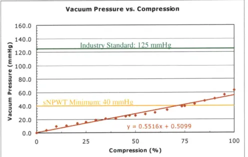
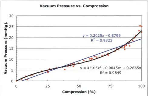
Figure 7.3: Typical vacuum pressure versus compression curve with a linear trendline; bellow s # 1... 103
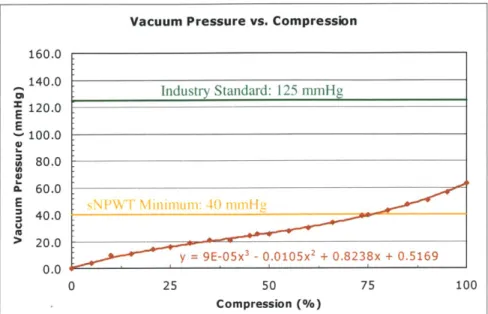
Figure 7.4: Typical vacuum pressure versus compression curve with a third-order polynomial trendline; bellows #1... . . 104
Figure 7.5: Expansion limiters manufactured from zip ties, nylon straps, and snaps ... 105
Figure 7.6: Typical vacuum pressure versus weight curve, taken at 100% compression; bellow s # 1... 106
Figure 7.7: Typical vacuum pressure versus compression curve for an added constant w eight of 67.6 N ; bellow s #1... 107
Figure 7.8: Typical vacuum pressure versus compression curve for an added constant w eight of 22.4 N ; bellow s #1... 109
Figure 7.9: Effective cross-sectional area versus compression curve; bellows #1... 110
Figure 7.10: Stiffness versus compression curve; bellows #1... 111
Figure 7.11: Image of the sequential compression of the toilet plunger-based bellows... 112
Figure 7.12: The 100cc Relivac® Evacuator ... 113
Figure 7.13: Typical vacuum pressure versus compression curve for the bladder pump... 115
Figure 7.14: Visual compression characteristics of the 100cc Relivac* Evacuator ... 116
Figure 7.15: Rolling diaphragm embodiment ... 120
Figure 7.16: Diagram of the rolling diaphragm pump variables ... 121
Figure 7.17: Diaphragm pump -typical vacuum pressure versus expansion length curve for m ultiple w eight values... ... 122
Figure 7.18: Diaphragm pump -typical vacuum pressure versus weight curve for an expansion length of 5.08 cm ... 123
Figure 7.19: Failure modes of the diaphragm ... 124
Figure 7.20: Typical cross-sectional area versus expansion length curve for rolling diaphragm pum p ... 125
Figure 7.21: TegadermTM and then... 137
Figure 7.22: Facem ask w ith frosting ... 137
Figure 7.24: Plastic grocery bag with frosting, covering a porous dressing... 138
Figure 8.1: Grip force experiment: subject placed her thumbs (left), or her palms and thumbs (right) on the side of the scale closet to her... 144
Figure 8.2: Helical bellows and dimensions ... 146
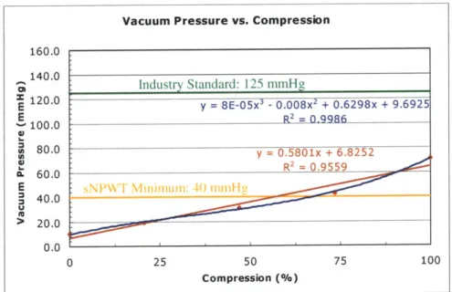
Figure 8.3: Vacuum pressure versus compression curve with a third-order polynomial trendline; helical bellow s... 148
Figure 8.4: Vacuum pressure versus compression curve for an added constant weight of 21.6 N with third-order polynomial trendline; helical bellows... 149
Figure 8.5: Effective cross-sectional area versus compression curve; helical bellows. ... 150
Figure 8.6: Stiffness versus compression curve; helical bellows. ... 150
Figure 8.7: Image of the sequential compression of the helical bellows... 151
Figure 8.8: COSMOSWorks@ model of the helical bellows. ... 153
Figure 8.9: Helical bellows with check valves (components 1 and 3), and pressure indicator (com ponent 2)... 155
Figure 8.10: Check valve in the bladder pump embodiment... 156
Figure A. 1: Photos of wounds on a patient's buttock and ankle before NWPT... 170
Figure A.2: Photos that show how the wounds on the patient's buttock and ankle... 171
Figure B .1: D im ensions of bellow s... 173
Figure B.2: Test set-up to measure bellow pressures at different compressions... 173
Figure B.3: Pressure data taken with brand new bellows #2... 174
Figure B.4: Pressure data taken with gas sterilized bellows #2... 174
Figure B.5: Typical vacuum pressure versus compression curve for an added constant w eight of 22.4 N ; bellow s # 1 ... 175
Figure B.6: Typical vacuum pressure versus compression curve for an added constant w eight of 40.9 N ; bellow s #1 ... 175
Figure B.7: Typical vacuum pressure versus compression curve for an added constant w eight of 59.5 N ; bellow s # 1 ... 176
Figure B.8: Typical vacuum pressure versus compression curve for an added constant w eight of 67.6 N ; bellow s # 1 ... 176
Figure B.9: Typical vacuum pressure versus compression curve for an added constant w eight of 80.5 N ; bellow s #1 ... 177
Figure B. 10: Typical vacuum pressure versus compression curve for an added constant w eight of 99.0 N ; bellow s # 1 ... 177
Figure B.11: Typical vacuum pressure versus compression curve for an added constant w eight of 118 N ; bellow s # ... 178
Figure B. 12: Typical vacuum pressure versus weight curve, taken at 0% compression; b ello w s # 1 ... 17 8 Figure B.13: Typical vacuum pressure versus weight curve, taken at 25% compression; b ellow s # 1 ... 179
Figure B. 14: Typical vacuum pressure versus weight curve, taken at 50% compression; b ello w s # 1 ... 17 9 Figure B.15: Typical vacuum pressure versus weight curve, taken at 75% compression; b ello w s # 1 ... 180
Figure B.16: Dimensions of rolling diaphragm pump... 181
Figure B. 17: Diaphragm pump -typical vacuum pressure versus weight curve for an expansion length of 3.05 cm ... 181
Figure B. 18: Diaphragm pump -typical vacuum pressure versus weight curve for an
expansion length of 3.81 cm ... 182
Figure B.19: Diaphragm pump -typical vacuum pressure versus weight curve for an
expansion length of 6.35 cm ... 182
Figure B.20: Diaphragm pump -typical vacuum pressure versus weight curve for an
expansion length of 8.10 cm ... 183
Figure B.21: Diaphragm pump -typical vacuum pressure versus weight curve for an
expansion length of 8.89 cm ... 183
Figure B.22: Diaphragm pump -typical vacuum pressure versus weight curve for an
expansion length of 10.2 cm ... 184
Figure B.23: Diaphragm pump -typical vacuum pressure versus weight curve for an
expansion length of 11.4 cm ... 184
Figure B.24: Diaphragm pump -typical vacuum pressure versus weight curve for an
expansion length of 12.7 cm ... 185
Figure B.25: Diaphragm pump -typical vacuum pressure versus weight curve for an
expansion length of 14.0 cm ... 185
List of Tables
Table 1.1: sNPWT therapy unit and dressing design parameters... 20
Table 1.2: sNPWT therapy unit and dressing embodiments ... 21
Table 1.3: Parameters for a bellows with a pressure range between 90 and 125 mmHg, and a therapy capacity of 300 mL volume... 22
Table 2.1: KCI therapy unit specifications... 41
Table 3.1: Average air leak rate for Experiments 1 and 2... 59
Table 4.1: Results of U.S. doctor and nurse interviews ... 72
Table 4.2: Results of U.S. military doctor interviews ... 73
Table 4.3: Results of third world doctor interviews ... 74
Table 4.4: Results of U.S. domestic patient interviews... 75
Table 4.5: Strategy FRDPARRC chart for sNPWT therapy unit ... 77
Table 4.6: Strategy FRDPARRC chart for sNPWT dressing ... 78
Table 4.7: Weighted attribution chart for sNPWT therapy unit ... 79
Table 4.8: Weighted attribution chart for sNPWT dressing ... 79
Table 5.1: Concept FRDPARRC chart for sNPWT therapy unit ... 83
Table 5.2: Concept FRDPARRC chart for sNPWT dressing ... 83
Table 5.3: Weighted concept selection chart for sNPWT therapy unit ... 91
Table 5.4: Weighted concept selection chart for sNPWT dressing... 92
Table 6.1: Embodiment FRDPARRC chart for sNPWT therapy unit... 94
Table 6.2: Embodiment FRDPARRC chart for sNPWT dressing... 95
Table 6.3: Embodiment weighted attribution chart for sNPWT therapy unit ... 97
Table 7.1: Dressing and sealing agent experiment matrix with experimental results ... 129
Table 7.2: Feasible dressing and sealing agent combinations, and their corresponding average number of hours to fill 300 mL with air leaks... 136
Table 7.3: Comparison of the TegadermTM seal with and without air leak detection ... 139
Table 8.1: Potential dimension and stiffness combinations for a bellows with a pressure range between 90 and 125 mmHg, and a therapy capacity of 300 mL volume... 143
Table 8.2: Experimental results for the female grip test... 144
Table 8.3: Optimal parameters for the helical bellows with 90 to 125 mmHg pressure range and 300 mL volum e capacity... 147
Table 8.4: Optimal parameters for the helical bellows with 90 to 125 mmHg pressure range and a m aximum length of 7.9 cm ... 147
Table C. 1: Calculations of mole flow rates for all feasible dressings ... 187
Table C.2: Calculations of volume flow rates for all feasible dressings ... 187
Table C.3: Calculations of mole flow rates for TegadermTM in air leak system comparison stu d y ... 18 8 Table C.4: Calculations of volume flow rates for TegadermTM in air leak system com parison study ... 188
Nomenclature
A effective cross-sectional area
Af cross-sectional area of frictional force
Ag cross-sectional area of gravitational force
C mathematical constant d diameter d distance traveled F applied force F frictional force Fg gravitational force
Fcs, force of linear compression spring
Fesn force of nonlinear compression spring
Fmax maximum applied force
Fss force of linear torsion spring
Ftsn force of nonlinear torsion spring
g gravitational constant
h height of column of fluid
k spring constant
K c coefficient constant for filtration
m mass
n number of moles
P pressure
P power
PC hydrostatic pressure within capillary
PMx maximum pressure
PO pressure of a fully compressed bellows with no added weight
Psystem system pressure
Pt hydrostatic pressure within interstitium
Q
flow rateQwound flow rate of wound exudate
R specific gas constant
T temperature
t time elapsed
Vsystem volume of the system
W work
W weight
x linear displacement from equilibrium
xmx difference in length between fully relaxed and fully compressed bellows
AP pressure drop
AV volume capacity
Ax stroke length
6 angular displacement from equilibrium
rCe osmotic pressure within capillary
)rt osmotic pressure within interstitium
p density
1 Introduction
1.1 Project Background
This thesis project is a continuation of a course project that originated in
Professor Alexander Slocum's Precision Machine Design course (2.75) at MIT, during the fall of 2005. At the beginning of the semester, a panel of medical doctors pitched their ideas of potential medical devices to be developed by a group of students in 2.75. The doctors that are selected by the students then play the medical role on the development teams throughout the semester. Dr. Robert Sheridan (Chief of Bum Surgery and Assistant Chief of Staff at the Shriners Bum Hospital, and Division of Burns and Trauma, Department of Surgery,
Massachusetts General Hospital [MGH]) expressed his interest in creating a sNPWT device, based on his disappointment with the current NPWT systems. With interest in the project, Brenden Epps, Kevin Lin, Richard Timm, and Danielle Zurovcik formed a team to attack the problem. They performed initial design work that explored sNPWT. Two sNPWT pump prototypes were created and analyzed, which were based on a bellows and siphon concept. Multiple wound dressings were also tested. The initial results were successful, and therefore, this thesis project was initiated.
In this study, a formal design process was implemented, as research was built on the initial results found in the Precision Machine Design course. All information presented in this thesis is from research performed after completion of the course, except for the dressing
analysis, which is explored in section 7.2 and is the 2.75 coursework contribution of
Danielle Zurovcik. Additionally, the bellows prototype tested in section 7.1.1 is a study that further analyzes the bellows prototype from the course project. Data from the course,
although providing initial concept performance data, were not detailed enough to make accurate decisions on the final design.
1.2 Current Study
The current study relates to the medical application of negative pressure wound therapy (NPWT). NPWT is a treatment that promotes wound healing by: increasing blood flow to the wound, promoting granulation tissue formation, removing interstitial fluid, decreasing bacterial counts, uniformly drawing the wound closed, and protecting the wound from the outside environment. It consists of: (1) a nonadherent, wound dressing used to fill the wound cavity (e.g., a sterilized medical sponge), (2) a drainage tube placed adjacent to or into the dressing, (3) an occlusive transparent film placed over the dressing and adhered to the skin to maintain a seal, (4) a collection container for drained fluids from the wound, and (5) a low pressure vacuum source. Using this therapy, a negative pressure between
40 mmHg and 200 mmHg is applied to the nonadherent dressing that is inserted in or over the wound (depending on wound type and depth) for a prescribed period of time. Dressings are frequently changed, as they are usually permitted a maximum application length of two to three days. Wounds approved for treatment with NPWT by the Food and Drug
Administration (FDA) that have been found to benefit from this therapy are: chronic
wounds', partial-thickness bums, pressure ulcers, acute wounds, dehisced wounds2, flaps,
traumatic wounds, diabetic ulcers, and graft-site preparation. NPWT has been clinically proven to speed the healing time by a factor of three or more, and to aid in complete
recovery. This study aims to simplify current NPWT systems for application in third world, military, disaster relief, and domestic environments through the development of simplified negative pressure wound therapy (sNPWT) devices.
A Deterministic Design Process was used to design the sNPWT devices [1]. This
design process begins with a complete background review, literature search, and kinematics study. Then, three iterative design tools: FRDPARRC Tables, weighted attribution charts, and the PREP Process, in conjunction with fundamental design principles, are used to yield creative, robust product designs. Both the sNPWT pump device and the dressing system
were analyzed using this process.
1 Wounds that do not heal conventionally within three months.
At first, the sNPWT mechanical concept was analyzed for its feasibility in replacing electrical, expensive NPWT systems. During this process, the limiting factor for sNPWT was identified as the high air leak rate into the current NPWT systems, which requires the systems to have a continuously powered vacuum pump. The main source of air leaks was found at the dressing/wound interface, and methods were explored to reduce air leak rate values to under 0.56 mL/min. This targeted air leak rate would allow the therapy to last for eight hours between resetting a mechanical pump with a 300 mL volume capacity. A
.3
300 mL volume capacity was chosen for safety reasons, relating to patient exsanguination.
Various dressings were found to satisfy this condition, as an air leak test was developed to visually detect any air leaks. Once sNPWT was proven to be viable, the FRDPARRC process was implemented.
The strategy of the project was to design for the customer needs and functional
parameters of sNPWT. With this strategy, a functional system would be produced that would enter the market with a pull, rather than push approach. Doctors, nurses, and patients from all targeted markets were interviewed to identify the customer needs, as an extensive study of NPWT was performed to further define the functional parameters. A list of identified
customer needs and functional parameters, for both the therapy unit (vacuum pump device) and dressing, is shown below in Table 1.1, with the top ranked parameters highlighted.
Table 1.1: sNPWT therapy unit and dressing design parameters (strategy components); top ranked parameters are highlighted.
sNPWT Therapy Unit sNPWT Dressing
Inexpensive Inexpensive
Accessible Accessible
Easy to Store Easy to Store
Easy to Assemble Easy to Apply
Easy to Use Applicable to Highly Contoured Surfaces
Safe (e.g., must not exsanguinate patient) Protects Wound from Erwironment
Portable Easy to Connect to Therapy Unit
Requires No Electrical Outlet Power or Wall Suction Sae (e.g., must be compatible with wound)
Apply a Constant 40 -200 mmg Vacuum Portable
Colects Exudate for Easy Disposal Evenly Distributes Vacuum Pressure
ReusablelSterilizable (Third World) Provides method for exudate removal
Dispsl oped World) Disposable
Therapy unit and dressing embodiments were then derived from these initial strategy components, from which the top ranked embodiments were prototyped and analyzed. All initial embodiments, with the top ranked embodiments highlighted, are listed in Table 1.2. The current study focused on the therapy unit, although many dressings were prototyped and tested. Designing a dressing would require significantly more FDA-related approval time and testing than the therapy unit. Therefore, the therapy unit was initially designed for use with currently available, commercial wound dressings. In this study, most efforts toward the dressing were focused on reducing air leaks.
Table 1.2: sNPWT therapy unit and dressing embodiments; top ranked are highlighted.
embodiments
After an initial analysis was performed to characterize the therapy unit embodiments, the plastic bellows pump (initial, accordion, toilet plunger-based model4) was determined to be the most desirable embodiment to meet the goals of this project. A detailed analysis was carried out to define the parameters of an optimal bellows design. The final design was
determined to have a therapy implementation from 90 to 125 mmHg (since the bellows applied vacuum pressure is not constant) and a volume capacity limitation of 300 mL. A table of potential parameters for this design is presented in Table 1.3 (a condensed version of Table 8.1). Relating to this table, the initial, accordion prototype did not have the desired dimensions. Therefore, bellows manufacturers were contacted for currently manufactured bellows with similar dimensions to the optimal design. Once obtained, the mold for this bellows can be used to vary the wall thickness, and thus the stiffness of the bellows.
4 The initial prototype system was constructed from a bellows-type toilet plunger.
sNPWT Therapy Unit sNPWT Dressing
Spring loaded syringe (constant force spring used CPR facemask with paint-on, spray-on, or
for constant pressure) manufacturer applied adhesive
Plastic beNows Round conformable rubber jar opener with paint-on, (for increased vacuum pressure, can place in spray-on, or manufacturer applied adhesive
paralel with additional spring, or can add weights in
series)
Bladder pump Round conformable rubber jar opener with no pump. Suction around wound cavity by jar opener suction seal alone. Adsorbent filler dressing placed in wound cavity
Inflating a balloon into a chamber, and opening the Sterilized plastic bag with paint-on or spray-on balloon to atmosphere adhesive to provide an occlusive dressing to cover
the wound cavity tiller dressing
Gravity governed, roling diaphragm Spray foam filler dressing with occlusive covering Siphon pump using two plastic containers and Sterilzed "kitchen" sponge with occulsive covering connection tube
Evacuated. rigid chamber with small hand pump Liquid Latex (or Liquid Latex-like) sealant to seal attached for charging occlusive dressing or conformable solid, or to act
as occlusive dressing itsel
Use a currently marketed medical dressing that works for sNPWT (such as current NPWT
dressings) and add additional sealing agents to decrease the air leak rate
Table 1.3: Parameters for a bellows with a pressure range between 90 and 125 mmHg, and a therapy capacity of 300 mL volume.
A (cm-) Ax (cm) k (N/m) F, (N) xa (cm) 54 5.6 446 89 20.0 62 4.8 599 103 17-3 71 4-2 790 119 15.0 81 3.7 1022 135 1312 92 3.3 1303 153 11.7 103 2.9 1638 171 10.4 114 2.6 2033 191 9.4 127 2.4 2496 211 8.5
In theory, with the proper dimensions and stiffness values, the optimal design can be achieved. This theory was tested with a helical bellows obtained from a bellows
manufacturer. The manufacturer claimed that the helical shape causes the bellows to have less memory when returning to their original length. However, after further analysis of the helical bellows, it was determined that the stiffness characteristics of bellows in general are dependent on their physical shape. The helical bellows had less desirable stiffness
characteristics than the accordion, toilet plunger-based model. Although this was discovered, the helical bellows are still a potential design option, if the volume capacity is reduced, or if the pressure range is expanded. Therefore, based on the project timeline, particularly for clinical trials, the helical bellows may be the best prototype option if no other bellows of the required dimensions can be obtained.
Clinical trials have been approved for the initial accordion-based bellows prototype, which has a maximum vacuum pressure of 63.1 mmHg. Once a new bellows is
manufactured achieving a pressure range of 90 to 125 mmHg, an addendum to the current clinical trials will be submitted, so that a larger patient poll will exist (typical therapy is approximately 125 mmHg). The results from the clinical trials are highly desirable, as soon as possible, as they will verify whether a non-constant vacuum pressure obtains successful therapy results and if sNPWT is beneficial.
2 Background
2.1 History of NPWT
The history of NPWT is controversial in its exact routes. There are many documented cases of negative pressure therapy in wound healing throughout history; however, their link to the present NPWT treatment is not clear. "Cupping" is the
terminology used for the earliest examples of negative pressure therapy, found predominantly in the eastern world. Cupping has been used in China for thousands of years, and its earliest documentation is in Bo Shu (an ancient book about silk, predating 28 AD), which was discovered in an ancient tomb of the Han Dynasty in 1973 (Chen Bin, Dr. He Chong, personal communications, 1995) [2].
Many different methods of cupping evolved over time. People originally used the horns of cattle for applying negative pressure, and it was often referred to as the "horn method." The horn was ignited to expel the air from inside the horn, and then it was used to withdraw pus and blood in the treatment of boils and carbuncles5. In another method, a hole was placed in the tip of the horn, and the caregiver would manually evacuate the air by mouth suction. Pressures achieved ranged from predominantly comfortable levels of low pressure to more painful higher pressures. Exact pressures are unknown [2].
Eventually, cupping spread into the western world, as the horns of animals were replaced by ceramic and glass cups, hollowed pumpkins, bamboo canes, and leeches [2]. As
the treatment grew more popular and was further investigated, its clinical applications grew to be applied in surgical practice, in the treatment of poisonous snake bites, and for bleeding diseases out of the body (also called blood letting). Cupping can still be found today in various cultures. In many cases, it has developed into a special therapeutic method, and it is currently the only poison removal method for snake bites in rural Africa [3]. Although not directly related to the modern NPWT treatments, cupping was the first to link negative pressure and wounds.
The development of modem NPWT treatments is unclear. The first widely recognized clinical use was in 1952, when Raffel introduced closed wound suction
drainage [4]. Prophylactic drainage was proven to greatly enhance wound healing, minimize postoperative complications, and reduce the duration of hospitalization following surgery [5]. Clinical studies confirmed the efficacy of wound drainage for a variety of uses, including the removal of an accumulation of fluid or cellular debris. Although the proof of concept began in 1952, it was not until the 1980s that this technology sparked a wide interest in the medical field [6].
In the early 1980s, constant pressure NPWT began to be researched by many surgeons and product manufacturers [6]. This increase in interest may be the result of healthcare systems' push to reduce costs, especially by decreasing the length of hospital stays. Both Russia and the U.S. were in the forefront of this technology. As seen in "The Kremlin Papers," Russia readily explored NPWT in the 1980s with positive clinical results in a variety of treatments. The studies showed that an intermittent therapy at low pressures, between 35 mmHg and 80 mmHg, provided the most beneficial treatment [7].
Much of the research in the U.S. was done at the Wake Forest University Baptist Medical Center, which reports their best clinical results at higher pressures (optimally
125 mmHg) with continuous suction [8]. Their NPWT system was originally developed by
Louis C. Argenta, M.D., Professor and Chairman of the Plastic and Reconstructive Surgery Department, and Michael J. Morykwas, Ph.D., Assistant Professor of Plastic and
Reconstructive Surgery Department. Wake Forest University patented their NPWT
apparatus and methods, and licensed the technology6 exclusively to Kinetic Concepts, Inc.
(KCI) of San Antonio, TX in October 1993. In 1995, KCI received 5 10(k) approval from the
FDA for their Vacuum Assistive Closure (V.A.C.®) System, which made them the sole
NPWT device manufacturer in the world.
At the turn of the century, NPWT was gaining wide acceptance in the medical field, as clinical trials continued to show positive results in increasing therapy applications. Then, 6 U.S. Patent 5,645,081, U.S. Patent 5,636,643, and Patent Serial No. PCT/US92/09649
in November 2004, the FDA approved a second device, the Versatile 1, which was manufactured by BlueSky Medical of Carlsbad, CA. They based their device on a flexible membrane technology developed in the 1980s by Dr. Katherine Jeter, D.Ed, ET, and the corresponding teachings of Dr. Mark Chariker [9]. This therapy resembles the intermittent, low pressure (optimally 80 mmHg for the Versatile 1*) practices of the Russians. Since the introduction of the Versatile 1*, Wake Forest University and KCI have sued BlueSky Medical for patent infringement and have lost all litigations to date [10].
2.2
Proof of NPWT
2.2.1 Scientific TheoryTwo scientific theories have been documented that aim to explain why NPWT promotes the healing of wounds. The first theory is based on mechanical principles, where as the second theory is based on human physiology.
2.2.1.1 Mechanical
The first theory is mechanical in nature, and suggests that the stresses and strains induced on tissue cells during negative pressure therapy (while using a porous, nonadherent dressing) promote wound healing. Research to support this theory has been funded by KCI, as it relates directly to their V.A.C.® system and the porosity of their sponge dressings. The
V.A.C.* system is in the class of micromechanical force (MMF) therapy devices. Relating to
previous studies performed with these devices, it is known that the mechanical environment of a cell causes a change in the gene expression profile of resident wound cells. However, the exact effect of mechanical forces on tissues and on wound healing is unknown.
In Dr. Dennis P. Orgill's Tissue Engineering and Wound Healing Laboratory at Brigham and Women's Hospital, Vishal Saxena sought to prove that mechanical forces are the underlying mechanism for NPWT success. He created a finite element analysis (FEA) model of the wound tissue and the V.A.C.* sponge under the operating conditions of
70 to 150 mmHg. A solid, linear elastic, isotropic, homogenous model was used to imitate
the tissues under consideration, as five parameters were varied: stiffness of the wound (Young's modulus of elasticity); compressibility of the wound (characterized by Poisson's ratio); pore diameter of the sponge (defined by the distance between two struts in the model);
pore volume fraction of the sponge; and pressure applied to the sponge (or differential thereof) [11].
Saxena's results suggest that the application of the V.A.C.* device exerts
and promoting wound healing. In a wounded tissue, the normal matrix may be degraded or severed. As Saxena's research explains, during V.A.C.® therapy, the tissue becomes seeded in the sponge, which then provides a mechanically continuous structure to overcome the loss of tissue integrity and substitute for the missing structural basis necessary for cell
proliferation. The FEA results support previous tissue research in that optimal strain levels are apparent in promoting tissue healing (-10 percent). By optimizing the sponge parameters based on the tissue parameters of a specific wound, it is hypothesized that the ideal sponge can be obtained for a particular wound to produce the optimal strains [11].
Supporting the FEA results, histologic evidence of wound tissue microdeformation in clinical wounds treated with the V.A.C.® system were compared to the FEA model
microdeformation. Histologic sections of wounds treated by the V.A.C.* system for four to seven days showed an undulating contour with protrusions and indentations corresponding to the geometry of the sponge's contact with the wound. The histologic contours resembled the contours obtained in the FEA models from compression applied at the sponge struts and tension between struts. This created an initial link between the FEA results and clinical data. Currently, the research at the Tissue Engineering and Wound Healing Laboratory aims to link the gene expression profile changes found in tissue under
2.2.1.2 Physiological
The second theory is based on human physiology, using the Starling-Landis equation, Equation (2.1), which was first hypothesized in 1896 by Starling and proven in 1926 by Landis. The Starling-Landis equation models the normal, pressure-related fluid leakage from a blood capillary into the surrounding tissue. It is also used to show that in a normal
circulatory system, pressure equilibrium exists through the capillary membrane, through the tissue spaces, and into the lymph capillary. This pressure balance dictates the equilibrium between fluid leakage from the blood capillary and fluid reabsorption into the lymph capillary in a normal circulatory system [12].
Net Filtration Across Capillary = Lymph Flow = KfC -[(P - P) - (fc K - r,)] (2.1)
In this equation, Pc and P, define the hydrostatic pressures within capillary and interstitium (i.e. tissue), respectively; and ,rc and z define the osmotic pressures within capillary and interstitium, respectively. Kc and
oe
define the coefficient constants for filtration and reflection, respectively.The filtration and reflection coefficients quantify characteristics that determine the permeability of the capillaries. The filtration coefficient, Ke, is the product of the hydraulic conductivity and the total surface area of all the capillaries in the given tissue. The rate that fluid passes through the capillary membrane increases with an increase in the filtration coefficient, for a given net pressure difference across the membrane. The reflection
coefficient, afc, represents the level of restriction of the pores in the capillary membrane to the diffusion of protein molecules; it is used to generate an effective osmotic pressure
difference. However, from a quantitative point-of-view, the reflection coefficient is often left out of the Starling-Landis equation, since normal values for non-visceral tissues are greater than 0.99, and when values reach as low as 0.80, death would have already occurred [12].
In chronic wounds, trauma to the blood capillary decreases the osmotic potential difference across the capillary wall. This increases filtration across the capillary to exceed
reabsorption at the lymph, which promotes rapid edema in the wound. NPWT applies a compression force in the wound that counteracts the increase in filtration pressure out of the blood in the capillaries and into the surrounding tissues, which improves the equilibrium between fluid leakage and fluid reabsorption [13]. Additionally, NPWT drains the accumulated edema in the wound. Therefore, by applying hypobaric oxygen conditions (negative gauge pressure) at the wound site, NPWT is believed to regain equilibrium in the wound, which promotes wound healing.
2.2.2 Clinical Studies
Extensive clinical trials have demonstrated the success of negative pressure in healing
FDA approved NPWT wound types. Evidence supporting the use of NPWT in the treatment
of chronic, non-healing wounds exists primarily in the form of nonrandomized, controlled trials; prospective and retrospective large and small case series; single-center studies; and single case studies, with few randomized, controlled clinical trials (RCT). Examples can be found in Appendix A. Proven medical benefits of NPWT treatment, based on clinical results, include:
" Promotes blood flow (perfusion) at the wound
" Removes interstitial fluid, bacteria, and infectious materials
* Increases rate of granulation tissue formation * Provides a protected, moist healing environment
" Draws the wound edges together " Reduces scar tissue formation
2.3
NPWT Market
NPWT is one of the newest, medically proven treatments for healing chronic wounds in the developed world. The market share of NPWT systems has significantly increased over the past five years (since 2000), as success rates in clinical trials have proven its healing ability. The NPWT market plays a significant role in the larger advanced wound
management market. KCI alone maintained a market share of 6.8% in 2004, and anticipated an acquisition of up to 15% [14].
2.3.1 Current Market
The current NPWT market expands into both U.S. and international healthcare systems. Based on data in Q4-05, the current U.S. domestic market entails 1.4 million patients (2.5% of U.S. chronic wound patients) who have chronic wounds that would significantly benefit from NPWT. Less than 20% of these patients were served by KCI's distribution across acute care hospitals, extended care facilities, wound clinics, home health care agencies, and patients' homes. No significant fraction was addressed by any other wound therapy company [15]. Another market segment for NPWT is the U.S. military market. KCI is a major distributor in the U.S. military wound management market, as a significant number of wounded soldiers and disaster victims receive NPWT [16, 17]. In
2005, KCI earned a total of $706 million in revenue from V.A.C.® rentals ($519.5 M) and
sales ($186.5 M) in their U.S. markets [18].
KCI also dominates NPWT international markets. KCI currently has operations in 17 countries: Australia, Austria, Belgium, Canada, Denmark, France, Germany, Ireland, Italy, Japan, the Netherlands, Singapore, South Africa, Spain, Sweden, Switzerland, and the United Kingdom. Most international revenue comes from the acute care setting. In 2005, KCI earned a total of $201.5 million in revenue from V.A.C.* rentals ($96 M) and sales
($105.5 M) in their international markets [18].
As described above, KCI is currently the key player in the NPWT market. Their agreements with group purchasing organizations (GPOs) and reimbursement under Medicare
Part B account for a significant portion of their total revenue [18]. KCI was the sole manufacturer of NPWT systems until 2005, and still captures over 99.9% of NPWT sales with their V.A.C.* system. However, new market pressures are quickly appearing. In
Q4-05, KCI expected the global V.A.C.® market to increase at an annual growth rate of 11 to
15% per year, which was significantly lower than previous years. This was due to an
increasingly competitive environment, based on direct and indirect competition, and lower reimbursement for negative pressure wound therapy supplies under Medicare Part B [18].
Despite KCI's low Q4-05 forecast, a strong global push for advanced dressings in the medical field continues to become more prominent. This is due to the projected increase in chronic wounds that require treatment, which is directly related to the increasing senior, obese, and diabetic populations. The push for advanced dressings is portrayed in the current market trends for wound healing. In general, health care systems are currently focusing on effective healing techniques to decrease the length of stay, and thereby reducing the overall cost of care incurred [14, 18, 19]. However, as experienced by KCI, the high costs of
advanced dressings, higher standards for reimbursement approval, and increased competition are major challenges to significant market penetration [19].
2.3.2 Targeted Market Expansion
This study aims to expand the NPWT markets, while positively impacting health care systems and patients with wounds. The focus for an inexpensive, purely mechanical sNPWT device increases the potential for possible NPWT application in the existing military and domestic markets. It also takes NPWT technology to a marketplace where wound therapy has not been implemented before: the third world market.
2.3.2.1 Domestic Market
The sNPWT systems could improve current domestic applications of NPWT. The inexpensive nature of sNPWT allows for an increased number of patients to afford NPWT, both in public and private care settings. Additionally, care facilities would be able to afford to store many sNPWT devices on their shelf for instant application, without the need to worry about rental timing issues or product availability. "The device is supposed to arrive within two hours," explained Dr. Sheridan at Shriners Burn Hospital, ready to administer NPWT to a patient. "We put the order in at 7:30 a.m. this morning, and here it is 12:30 p.m, and no machine has arrived yet. This is not uncommon, and is something that we have to deal with [20]."
The lightweight characteristic of sNPWT significantly increases the product value. Currently, at Shriners Burn Hospital, Dr. Sheridan explains that "children are limited in their activities, based on the heavier weight and electrical requirement of the current V.A.C.*
system used [20]." Many patients of all ages that receive NPWT are immobilized more from the NPWT device, than their medical condition. Current NPWT is found to be prohibiting, even to patients in wheelchairs. In general, the aging population is becoming more active, requiring products that allow for increased mobility [14].
While improving the current NPWT treatment, sNPWT expands the domestic NPWT market into new segments. With its low cost, easy use, and long shelf life, sNPWT devices have the potential to be distributed at local, medical, retail stores for at-home or travel use. It can be used for wound management of minor scrapes, cuts, and burns that would normally be
managed by store-bought bandages. An ideal implementation would be in first aid kits, for environments such as athletic events, construction sites, machine shops, and camping.
2.3.2.2 Military and Disaster Relief Markets
Due to its lightweight, small size, and lack of electrical requirement, the sNPWT device allows for possible application directly in the field, and increases the ability to transfer patients, especially in austere environments. Specific general instances that would benefit from sNPWT are:
" NPWT is currently unavailable on the battlefield with the nearest administration
in field hospitals. In these hospitals, power supply is a major issue, as generators are sometimes used to supply power to only six outlets.
" The National Guard frequently performs emergency rescue missions in severe
environments, and treatment cannot be started until returning to hospital facilities. * Electricity is not always reliable during battle or rescue missions, especially when
forced to rely on local utilities.
The U.S. Armed Forces would greatly benefit from the sNPWT devices. Specifically, 25,378 members of the U.S. Armed Forces were wounded in action between the initial invasion of Iraq in 2003 and 15 May 2007 [21]. There are currently no standardized or optimized methods of casualty management that prevent or minimize deficits and provide for speedy wound healing [22]. All wounds are left open for transport. Currently, negative
pressure dressings, such as vacuum-assisted closure (V.A.C.*; Kinetic Concepts, San Antonio, Texas), are frequently used in fixed facilities along the evacuation chain, but they are expensive and not approved during flight [17, 23].
The importance of NPWT in disaster relief efforts was experienced during the 2004 tsunami disaster in Southeast Asia. Victims received traumatic injuries to the head, chest, and limbs that were contaminated with drug resistant bacteria. The victims that were European citizen tourists were taken by Medical Evacuation (MedEvac) aircrafts and distributed among various care facilities. It was at these facilities that microbiological assessment showed significant contamination issues in all open-wounded patients. At the Cologne-Merheim Medical Center in Germany, these contaminants were controlled through aggressive and repetitive debridement, together with vacuum-assisted closure for the
interium [24]. With sNPWT, disaster relief can afford to stock lightweight, inexpensive sNPWT devices to administer at ground zero facilities and in other situations involving
.7
injuries with dermal disruption .
2.3.2.3 Third World Market
There are over 4.5 million third world cases of chronic, and potentially debilitating,
wounds [25]. Although these wounds may be caused by many complications, they are most
often found in patients that are malnourished or have poor blood circulation, such as diabetics. They frequently occur in the form of an ulcer that develops from trauma to the lower extremity of the body. This trauma ranges from continuous rubbing of the skin, for example the rubbing of shoes on the foot, to the scratching of an irritation, to impact trauma
wounds, such as a bruise. Also, hitting hard in the developing community are accidental puncture wounds to individuals in the prime of their working years. Small initial scrapes and
cuts continue to go untreated in unsanitary conditions, until it is debilitating to the individual. Some of these wounds take years to heal, as others may never heal, causing great emotional, physical, and financial stresses [20].
In the third world, chronic wounds are commonly left untreated until wound management is absolutely necessary and wound severity has significantly increased. Most wounds are left untreated, due to the lack of treatment methods available in the localized community and lack of affordability in seeking medical attention. As time progresses, the patient's pain increases, causing everyday activities to become a hurdle. Performing the manual labor common for third world employment becomes too difficult to satisfy quotas.
By the time the proper medical attention is received, many wounds have encountered
infection or disease, and potentially require amputation [20].
Currently, the 4.5 million chronic wounds in the third world are usually treated by debridement and then the application of various dressings. These dressings consist of inexpensive gauzes, patches, and films readily available in the clinics (private clinics treat
10% of patients) and hospitals (public hospitals treat 90% of patients). However, these have
no wound specific healing agents other than protection from the outside environment [20]. The most common treatment offered at care facilities is the application of wet-to-dry dressings (dressings that are applied moist with saline and allowed to dry before
the wound sticks to it. It is assumed that wound debridement occurs when the dressings are removed and replaced. These dressings are also commonly used in the United States. Their effectiveness and benefits are often debated [27].
It is estimated that a minimum of 2.5% of wounds in the third world are good candidates for NPWT (using the same percentage as the U.S, even though wound incidence and the potential for complications are significantly higher in the third world) [15]. NPWT is not readily available in the third world due to its current high cost, electrical need, and
economic complexity [20]. The device developed in this study would provide an affordable, applicable NPWT treatment for the austere environments encountered in the third world.
2.4 Current Products
The two market leaders of current NPWT devices are Kinetic Concepts Inc. (KCI) and BlueSky Medical. Their products fixed cost range from $15 K to $20 K for the therapy unit (approximately $120 per day to rent) and $20 to $30 per disposable dressing [28, 29]. The devices of both companies require a 100 to 240 VAC, 50 to 60 Hz, electrical supply, in order to power the pump, microprocessor systems, digital displays, and to allow for
significant air leaks in their systems.
Air leaks may occur at the dressing seal or at various connections in the system, and increased power is needed to pump this excess fluid. A threshold exists for the amount of air leaks allowed into the system, which is signified by a therapy shut-off alarm. As the alarm sounds, therapy is automatically stopped until the device is manually reset and the detected air leaks fall below the threshold value. Another key safety feature that is currently powered
by the microprocessor and sensory system is the detection of rapid blood flow into the
exudate collection chamber that powers-off the device. If a vein or artery is ruptured during therapy, negative pressure therapy has the potential to exsanguinate the patient. Thus, air
leak detection and blood flow detection are often coupled into the same sensory system.
Due to the need for a 100 to 240 VAC electrical supply, high fixed cost, seal
complexity, and microprocessor system operation, these devices are applied only by a trained professional and have a significant lack of transportability. A few designs have addressed the transportability issue with an additional battery option; however, these batteries typically only last for less than 4 hours. Batteries also introduce the issue of battery management for recharging purposes, and therefore, these new devices are not widely accepted for use in a hospital-type setting.
Besides NPWT systems, other medical dressings exist that are used for wound treatment. Although these products do not apply NPWT, they compete in the wound healing market, and are more of a direct competitor as sNPWT aims for treatment options in austere environments and in the domestic market.
2.4.1 Kinetic Concepts Incorporated
Kinetic Concepts Incorporated (KCI) is a company based out of San Antonio, Texas that manufactured the first NPWT device on the market in 1995, the V.A.C.® Therapy System. Since its initial launch, this device has been clinically proven to promote wound healing, to decrease the length of hospital stay, and to decrease the incidence of
complications. It is supported by "one of the most substantial clinical evidence bases in wound care [30]." Some of these clinical trials are discussed in Appendix A [31].
Since KCI has pioneered the NPWT industry with their V.A.C.® Therapy Systems, their product specifications and trends were thoroughly researched to understand the grounds for future advancements. The history of the industry is also represented through their
product innovations.
Since the launch of the original V.A.C.* Therapy System, Kinetic Concepts has expanded their NPWT market with additional devices, dressings, and accessories to meet their customer demands. Therapy unit innovation has focused on increasing transportability
by decreasing size and weight and increasing battery life. There has also been a focus on
medical-related technologies, as seen in the V.A.C.* Instill® System. In this system, instillations of wound healing agents are capable of being directly injected into the wound bed during V.A.C.® Therapy. Currently, KCI offers three therapy units: V.A.C.® ATS®
System, V.A.C.* Freedom® System, and V.A.C.® Instill® System, along with a separate
V.A.C. Freedom® Car Adapter accessory, for charging its battery. The descriptions and
specifications of these products are outlined in Table 2.1, and a picture of each therapy unit is shown in Figure 2.2 [32, 33, 34, 35].
Table 2.1: KCI therapy unit specifications [32, 33, 34, 35].
_ Sp cification
Products) DescriDtion W x H x D Wtt Negative Elect. Battery Life Cost per Unit CPT
I s) Pressure Range Power thrs) ($/day rental) Codes
tmmHal ___
Designed for higher acuity
VAC I ATS 0 System wounds for patients in acute 14.6"x11"x7.1" 12 3 50-200 Yes 4 $120 976W6 VA ®AT Sstm care and long-term care (70W) -10 97606
facilities.
VAC 0 Freedom ® System A norble syste alng 6.6"x3.1 x7 5" 32 50-200 Yes -12 97606
Automated delivery of topical
wound solutions to wound Yes 97605/
VAC 9 Instill 8 System sites via Instill Therapy' 15.6"x1"x7.1" 14,6 50-200 (70W) -4 97606
combined with V-A C-0 Therapy.
Dressing innovation has aimed for easier dressing application, shorter dressing changes, and patient comfort. Many of the innovations lie in dressings for specific
application in highly contoured areas of the body, which are difficult to seal. The original porous dressings were sized to fit the wound by manually cutting the foam. New dressings were invented with perforations to provide easy customization of dressing width and depth. Medical innovation was also applied to the V.A.C.® GranuFoam* Dressing by
micro-bonding metallic silver evenly throughout the dressing in the V.A.C. GranuFoam® SilverTM, introduced in 2005. Silver has been proven beneficial in wound healing for its antimicrobial properties [36].
Various iterations exist of two types of porous dressings: V.A.C.* GranuFoam® and
V.A.C.® Vers-FoamTM, which are inserted into the wound and sealed with the original
occlusive dressings: V.A.C.* Drape® and V.A.C.® Extra-Large Drape. The descriptions and specifications of these products are outlined in Figure 2.1, with information taken directly from product brochures [36, 37]. A picture of the products is shown in Figure 2.2.