HAL Id: hal-00078113
https://hal.archives-ouvertes.fr/hal-00078113v2
Submitted on 10 Nov 2006
HAL is a multi-disciplinary open access archive for the deposit and dissemination of sci-entific research documents, whether they are pub-lished or not. The documents may come from teaching and research institutions in France or abroad, or from public or private research centers.
L’archive ouverte pluridisciplinaire HAL, est destinée au dépôt et à la diffusion de documents scientifiques de niveau recherche, publiés ou non, émanant des établissements d’enseignement et de recherche français ou étrangers, des laboratoires publics ou privés.
thin metallic film
Antoine Moreau, Christophe Lafarge, Nicolas Laurent, Kofi Edee, Gérard
Granet
To cite this version:
Antoine Moreau, Christophe Lafarge, Nicolas Laurent, Kofi Edee, Gérard Granet. Enhanced trans-mission of slit arrays in an extremely thin metallic film. Journal of Optics A: Pure and Applied Optics, IOP Publishing, 2007, 9, pp.165-169. �hal-00078113v2�
hal-00078113, version 2 - 10 Nov 2006
extremely thin metallic film
A. Moreau, C. Lafarge, N. Laurent, K. Edee and G. Granet
LASMEA, UMR CNRS 6602, Universit´e Blaise Pascal, 24 avenue des Landais, 63177 Aubi`ere, France.
Abstract. Horizontal resonances of slit arrays are studied. They can lead to an enhanced transmission that cannot be explained using the single-mode approximation. A new type of cavity resonance is found when the slits are narrow for a wavelength very close to the period. It can be excited for very low thicknesses. Optimization shows these structures could constitute interesting monochromatic filters.
Since the discovery of Ebbesen that subwavelength hole arrays could transmit light,[1] much has been understood concerning the behavior of such structures. Resonances of the structure are responsible for the extraordinary transmission. Two types of resonances are usually involved : surface resonances (surface plasmons, often refered to as horizontal resonances) and cavity resonances (or vertical resonances).
Slit arrays (in the case of TM polarization) first attracted much attention, for they were considered simpler than hole arrays. Porto et al were the first to introduce the single-mode approximation which allows to understand the enhanced transmission[2]. They came to the conclusion that both surface plasmon resonances and cavity resonances were responsible for the enhanced transmission. These structures were then much been studied on this basis[3, 4, 5, 6]. The controversy began when Cao and Lalanne expressed the idea that the surface plasmons could even hinder the transmission[7]. The controversy is not closed yet[8, 9, 10].
Finally, hole arrays appear to be much better understood now than slit arrays. Surface plasmons are responsible for the transmission in the case of circular holes[5, 11, 12]. For coaxial hole arrays, the excitation of cavity modes explains the enhanced transmission[13, 14].
This paper deals with the case of subwavelength slit arrays in the visible domain. Many previous works concern the infra-red domain[2, 3, 6]. The permittivity of silver and gold in this domain is very high, so that the wavelength at which the surface plasmons can be expected are very close to the apparition of a new diffraction order. It is difficult in this case to distinguish between surface resonances and Rayleigh anomalies. Our purpose is to have a sound discussion about the different modes of the structure, using previous results on this subject[3, 4, 10]. The single-mode approximation and the limits of its validity have a central role in the discussion. In the following, we show that cavity resonances can be excited for very low thicknesses of the structure, and that there are resonances even when the one-mode assumption is not valid any more.
1. The single-mode approximation
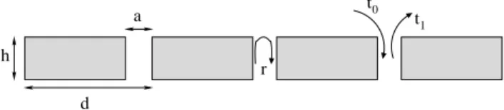
Let us consider a slit array (see figure1), whose parameters are its thickness h, its period d and the width of the slits, a. The metal considered here is silver. The optical constants of silver are taken from [15]. In the following, we will consider only the case of TM polarization, since the enhanced transmission occurs for this polarization only.
t0 t1 a d h r
Figure 1. Geometric parameters of the slit array.
always propagative. It corresponds to the excitation in each slit of the only mode which has no cut-off, in TM polarization. The slits can be considered independent.
It has been early recognized[2] that taking this only mode into account is enough to explain the enhanced transmission of the slit array. This is the single-mode approximation. Some more elaborate models have been proposed[6, 3] which rely on more assumptions about the propagating mode or the coupling between the incident wave and the guided mode. We will not use such approximations here.
The assumption that only the propagative Bloch mode is responsible for the extraordinary transmission leads to a classical Fabry-P´erot formula for the zero-order transmittance of the whole structure [2, 3, 10] :
T = t0t1eiβ h 1 − r2 e2iβ h 2 (1)
where h is the depth of the structure, and β = 2π
λg is the propagation constant of the
guided mode and λg its effective wavelength. The coefficient t0 is the transmission
coefficient between the incident wave and the propagative Bloch mode, while t1 is the
transmission coefficient between the propagative mode and the plane wave (see figure 1).
This model allows to explain the resonances of the full structure using the properties of the semi-infinite structure - that is to say the interface between air and the slit array. The coefficients r, t0 and t1 can actually be found in the scattering matrix of this
interface alone, while T belongs to the scattering matrix of the whole structure with a finite thickness. The discussion will now focus on the modes of these two structures (the semi-infinite one and the whole structure), which correspond to poles of their respective scattering matrixes[4]. The study of these poles has been early recognized as central[3] and they have recently attracted some attention[10].
The horizontal modes[4] can be defined as the modes of the semi-infinite structure, since they correspond to an enhanced field at the interface between air and the slit array. As we will see, these modes may or may not be responsible for the enhanced transmission of the whole structure. The resonances which appear for the full structure only and which cannot be related to any horizontal mode will be called “vertical resonances”.
In this work, the scattering matrix is computed using the Rigorous Coupled Wave Analysis[16, 17]. It is easy to identify the only propagative mode among the Bloch modes of the slit array, using its propagation constant β. Then the coefficient r, t0 and
t1 are taken from the scattering matrix. As was shown in previous works[3, 6] a full
numerical approach is not necessary for the determination of these coefficients since the propagative mode is very close of the propagative mode in a perfect metal waveguide. But we will not use any of these approximations here.
The one-mode assumption is very accurate[3, 6, 10]. It perfectly accounts for all the observed enhanced transmissions until now : an enhanced transmission occurs when the denominator of (1) is close to zero. This occurs when two conditions are fulfilled. First the modulus of r should not be null, and should be as close to 1 as possible. Second, if
we denote φ the phase of r, the resonance condition can be written
φ(λ) + β h = m π, (2)
where m is an integer.
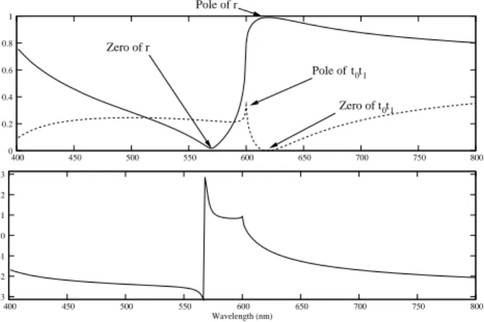
Figure 2 shows a typical internal reflexion coefficient r for a period d = 600 nm and a slit width a = 100 nm and the modulus of t0t1. These quantities are enough to fully
understand the properties of the slit array.
t t0 1 Zero of t t0 1 Pole of Pole of r Zero of r 0 0.2 0.4 0.6 0.8 1 400 450 500 550 600 650 700 750 800 −3 −2 −1 0 1 2 3 400 450 500 550 600 650 700 750 800 Wavelength (nm)
Figure 2. Typical example of |r| (top, solid line), |t0t1| (top, dotted line) and φ
(bottom, solid line) for the semi-infinite structure with d = 600 nm and a = 100 nm.
2. Horizontal resonances
We will now try to identify the resonances of the semi-infinite structure. Since it has been demonstrated that the propagative mode is the only one responsible for the enhanced transmission, one can expect the coefficients r, t0 and t1 to present poles for these
horizontal resonances.
Two poles can be identified in figure 2 : one on |r| and one on |t0t1|.
2.1. Pole of r
The pole of r has already been much studied[3, 10]. It is located at the very wavelength where a surface plasmon can be expected in normal incidence for λ > d. The wavelength of the surface plasmon resonance is given by[2, 3, 7]
λ= d Re v u u t ǫ(λ) 1 + ǫ(λ) . (3)
Since the modulus of r is close to one near this resonance, it was first considered responsible for the enhanced transmission that could occur in the vicinity of λp[3],
strengthening the conclusion that the horizontal resonances played an important role[2]. But, as underlined[7, 10], t0t1 presents a (real) zero for the same wavelength so that
reflection coefficient r is close to 1, t1 goes to zero and so does t0 because of reciprocity.
Actually t0 and t1 very slightly differ because the metal is lossy, but they present the
same poles and zeros.
This behavior can be explained by the nature of this horizontal resonance : it corresponds to the excitation of two counter-propagative surface plasmons which interfere destructively above the slits so that (i) the propagative mode of the slits is not excited and (ii) the location of the pole of r (and subsequently of the zero of t0t1) is
exactly λp and does not depend on the size of the slits. Figure 3 shows the field at the
surface of the semi-infinite structure for d = 600 nm and a = 10 nm at λ = λp. The
horizontal resonance can clearly be seen, and almost no field is present in the slits. This is the case even for higher values of a.
Figure 3. Modulus of Hy for the semi-infinite structure with d = 600 nm, a = 10 nm
and λ = λp= 618 nm. A surface resonance is clearly excited. There is almost no field
inside the slits. The borders of the structure have been represented in white.
Practically, the transmission presents a zero for λ = λp, exactly when the horizontal
mode is excited so that it is difficult to consider this resonance responsible for the enhanced transmission.
Moreover, the first works agreed that all the enhanced transmission that have been numerically observed until now occur when (2) is satisfied[3]. All the resonances then present all the properties of Fabry-Prot resonances, or cavity resonances[5]. This is why we think that they should all be labeled “vertical resonances”[4].
We think that the sharpness of a resonance should not be used as a criterium to determine whether a resonance is horizontal or vertical[2, 4, 3]. Otherwise this leads to apparent paradoxes[9].
2.2. Pole of t0t1
Let us consider the second horiizontal resonance, that has not been studied in previous works[10] mainly because t0t1 has not attracted all the attention it deserves[3].
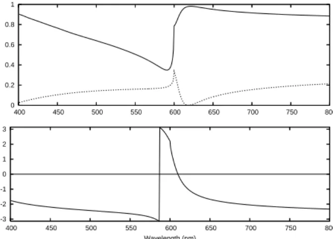
First, does the observed peak really correspond to a surface resonance ? Figure 4 and 5 show the behavior of the usual coefficients when d = 600 nm and when a becomes smaller (respectively a = 40 nm and a = 10 nm). For a = 40 nm the zero of r is the only remarkable feature which moves : it is heading towards λ = d, and off the real axis and the rapid variation of the phase is following this zero. For very low values of a, the peak of t0t1 moves towards λp and a minimum of r appears at the very wavelength of
0 0.2 0.4 0.6 0.8 1 400 450 500 550 600 650 700 750 800 -3 -2 -1 0 1 2 3 400 450 500 550 600 650 700 750 800 Wavelength (nm)
Figure 4. Modulus of of r (top, solid line), |t0t1| (top, dotted line) and phase of r
(bottom, solid line) for the semi-infinite structure with d = 600 nm and a = 40 nm. The zero of r moves towards the left, and the quick variation of the phase follows. The poles of r and t0t1do not move.
0 0.2 0.4 0.6 0.8 1 400 450 500 550 600 650 700 750 800 -3 -2 -1 0 1 2 3 400 450 500 550 600 650 700 750 800 Wavelength (nm)
Figure 5. Modulus of of r (top, solid line), |t0t1| (top, dotted line) and phase of r
(bottom, solid line) for the semi-infinite structure with d = 600 nm and a = 10 nm. The pole of t0t1 moves towards the pole of r. It is located at λ = 608 nm.
Figure 6 shows the modulus of the magnetic field in the case of the semi-infinite structure for d = 600 nm and a = 10 nm at the wavelength of the peak of t0t1
(λ = 608 nm). It has all the characteristics of a horizontal resonance : the field is enhanced near the interface. This time, there is a constructive interference of the surface modes above the slits so that (i) the propagative mode inside the slits is easily excited and thus t0 and t1 present a peak and (ii) the position of this peak strongly depends on
the size of the slits and is not located at λ = λp.
When the thickness h of the slit arrays is rather large, this horizontal resonance is responsible for a peak in the spectrum at λ = d, which is perfectly well reproduced by the one-mode model. Absolutely no cavity resonance is involved in this phenomenon for the denominator of (1) does not present any noticeable minimum in this range.
Figure 6. Modulus of Hy for the semi-infinite structure with d = 600 nm, a = 10 nm
and λ = 608 nm. A surface resonance is clearly excited. It is very well coupled to the propagative mode inside the slits.
0 0.2 0.4 0.6 0.8 1 400 450 500 550 600 650 700 750 800
Zero-th order transmittance
Wavelength (nm)
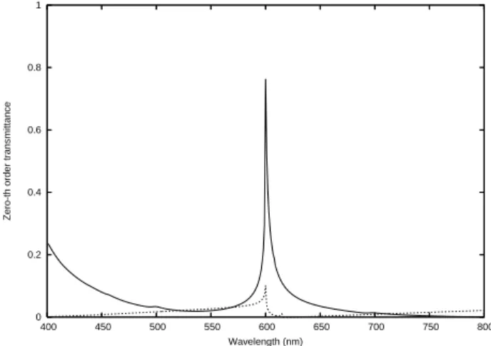
Figure 7. Zero-th order transmission of a slit array with d = 600 nm,a = 51.37 nm and h= 33.89 nm (solid line) and the single-mode approximation result (dashed line). The one-mode model is clearly inaccurate for these parameters : the enhanced transmission is due to the excitation of a horizontal resonance. The geometrical parameters have been obtained using optimization (see thereafter).
much more intense transmission for λ = d (see figure 7). This transmission cannot be explained using the single-mode approximation, since the one-mode model reproduces very poorly the enhanced transmission. This means that not only the propagative mode is excited by the surface resonance. Many evanescent modes obviously are excited. While h is large, they do no take part to the transmission, but they do when h is small enough. Such a resonance cannot have been studied up to now, since all the resonances in previous works[2, 3, 4, 10] are very accurately described by the one-mode model. The only exception, in a sense, is a recent and interesting work in the case of TE polarization[8].
3. Cavity resonances at very low thicknesses and optimization
When h is very small compared to the wavelength, no vertical resonances (or cavity resonances) are expected[2, 18, 5, 10]. This may be true when r is real, but around λ= d the phase of r takes all the values in [−π, π] so that cavity resonances should be expected for any height.
0 0.2 0.4 0.6 0.8 1 400 450 500 550 600 650 700 750 800
Zero-th order transmittance
Wavelength (nm)
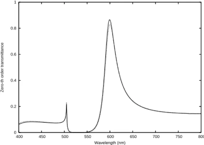
Figure 8. Zero-th order transmission of a slit array with d = 504.9 nm,a = 115.7 nm and h = 127.9 nm (solid line) and the single-mode approximation result (dashed line). The peak at λ = 504.9 nm is due to the excitation of the horizontal resonance on both sides of the structure. The parameters of this structure have been found using optimization, so that the 0 resonance has a maximum @600 nm.
If h is small, then the cavity resonances can be found either when m = 0 in equation (2) (in that case the phase of r is negative an close to zero and the resonance will be called “0 resonance”) or when m = 1 (in that case the phase is positive and close to π and the resonance will be called “π resonance”).
The 0 resonances are expected near the location where the phase is null, for a wavelength λ > λp but very close to λp. When h goes towards zero, the position of the
0 resonance will come very close to λp. Since there is a zero of t0t1 for λ = λp, the 0
resonance is almost non existent in this limit. Finally, the 0 resonances cannot produce a very enhanced transmission under a certain thickness.
A typical spectrum is shown figure 8 where a 0 resonance is clearly seen. For λ = λp a zero of the transmission can be observed. This is what happens in[3] at low
thicknesses. Let us stress that 0 resonances have been widely studied[3, 10] and are not new.
The geometrical parameters of the structure have been obtained using a genetic algorithm in order to get the best transmission possible at 600 nm. More precisely, the objective function which is minimized is |1 − T (600)| + T (400) + T (750) where the transmittance T is computed using the full RCWA (with no approximations). The thickness is limited to 150 nm in order to have only one resonance and thus a monochromatic filter. Such resonances are usually observed for relatively large values of the slit width[2] and we imposed a > 70 nm. Even if the resonance provides a very intense transmission, the slits are so wide that the propagative mode is easily excited. The transmission is quite high at any wavelength (except near the plasmon resonance). The one-mode approach is perfectly valid for these conditions.
The π resonances are found when the phase is close to π. Figure 2 shows that this happens near the zero of r. Thus for a = 100 nm no π resonance can be excited at all,
since |r| 6= 0 is required to observe a minimum of the denominator in (1). But figure 5 shows that for narrower slits the zero of r goes off the real axis. Even if |r| is not very high, this can produce a peak in the transmission which can then be attributed to a π resonance. This peak is generally very narrow because the phase varies quickly in the range where the π resonances appear.
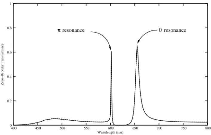
It is possible to observe a 0 resonance and a π resonance on the same spectrum. Figure 9 shows such a situation for d = 600 nm, a = 45.5 nm and h = 120 nm. The π resonance happens for a wavelength which is around 602 nm < λp. The 0 resonance is
wider and is found for a wavelength greater than λp, while there is a zero of transmission
for λ = λp. The one-mode model is found to be very accurate.
πresonance 0resonance 0 0.2 0.4 0.6 0.8 1 400 450 500 550 600 650 700 750 800
Zero−th order transmittance
Wavelength (nm)
Figure 9. Zero-th order transmission of a slit array with d = 600 nm,a = 45.5 nm and h = 120 nm (solid line) and the single-mode approximation result (dashed line). The O and the π resonance can be seen on the same spectrum.
We have performed the same optimization for π resonances than previously, except imposed a < 70 and a period d < λp to be sure of the nature of the resonance. The
obtained structure has a period of 600 nm, a slit width of a = 45.5 nm and a thickness of only 60.5 nm. The resulting spectrum is shown figure 10. It can be seen that the one-mode approach is correctly predicting the position, the width and the intensity of the enhanced transmission even if this is not the case at other wavelengths. That is why we think that the peak in the transmission spectrum can be considered as a cavity resonance, but with a cavity which is only 60 nm only thick. The resonance is found at 600 nm precisely. This is probably the optimal solution because in this case the minimum of the denominator of (1) occurs when there is a maximum of t0t1.
4. Conclusion
We have thoroughly studied the behavior of slit arrays for low thicknesses. We defined horizontal resonances as modes of the semi-infinite slit array, and vertical modes as resonances of the finite-thickness structure that cannot be related to horizontal resonances.
0 0.2 0.4 0.6 0.8 1 400 450 500 550 600 650 700 750 800
Zero-th order transmittance
Wavelength (nm)
Figure 10. Zero-th order transmission of a slit array with d = 600 nm,a = 45.5 nm and h = 60.5 nm (solid line) and the single-mode approximation result (dashed line). The parameters of this structure have been found by optimization, so that the π resonance presents a maximum @600 nm.
We identified two horizontal resonances. The first one is well known, it can be found for λ = λp the wavelength for which surface plasmons are expected. The second
one had never been studied and can be found exactly for λ = d provided the slits are wide enough.
The first one cannot lead to an enhanced transmission. The second one can lead to an enhanced transmission provided the thickness of the structure is so small that the single-mode approximation is not valid any more. Finally, any extraordinary transmission that is accurately described by the one-mode model is a vertical resonance (or cavity resonance).
We have found a new type of cavity resonance which can be excited for suprisingly low thicknesses. This type of resonnance can be excited provided the slits are narrow enough. It can be found around λ = d and always for λ < λp. It is a very narrow
resonance, so that slit arrays could constitute very effective monochromatic filters. We have optimized the transmission spectrum of the structure in that direction.
We hope this work will provide its readers with a convenient picture of the optical behavior of extremely thin slit arrays.
Acknowledgments
The authors are grateful to Philippe Lalanne for his suggestions and the attention he paid to our work.
References
[1] Ebbesen T W, Lezec H J, Ghaemi H F, Thio T and Wolff P A 1998 Nature 391 667 [2] Porto J A, Garcia-Vidal F J and Pendry J B 1999 Phys. Rev. Lett. 83 2845
[4] Collin S, Pardo F, Teissier R and Pelouard J L 2001 Phys. Rev. B 63 033107 [5] Popov E, Nevi´ere M, Enoch S and Reinisch R 2000 Phys. Rev. B 62 16100
[6] Lalanne P, Hugonin J P,Astilean S,Palamaru M and M¨oller K D 2000 J. Opt. A: Pure Appl. Opt. 248-51
[7] Cao Q and Lalanne P 2002 Phys. Rev. Lett. 88 057403
[8] Moreno E, Martin-Moreno L and Garcia-Vidal F J 2006 J. Opt. A : Pure Appl. Opt. 8 S94 [9] Jiao X, Wang P, Tang L, Lu Y, Li Q, Zhang D, Yao P, Ming H and Xie J 2005 Appl. Phys. B 80
301
[10] Lalanne P, Sauvan C, Hugonin J P, Rodier J C and Chavel P, 2003 Phys. Rev. B 68 125404 [11] Bonod N,Enoch S,Li L,Popov E and Neviere M 2003 Opt. Expr. 11 482
[12] Lalanne P,Rodier J C and Hugonin J P 2005 J. Opt. A : Pure Appl. Opt 7 422 [13] F.I. Baida and D. Van Labeke 2002 Opt. Comm. 209 17
[14] Moreau A, Granet G, Baida F I and Van Labeke D 2003 Opt. Expr. 11 1131 [15] Johnson P B and Christy R W 1972 Phys. Rev. B 6 4370
[16] Lalanne P and Morris G M 1996 J. Opt. Soc. Am. A 13 779 [17] Granet G and Guizal B 1996 J. Opt. Soc. Am. A 13 1019