HAL Id: hal-01999001
https://hal.archives-ouvertes.fr/hal-01999001
Submitted on 13 Mar 2020
HAL is a multi-disciplinary open access
archive for the deposit and dissemination of
sci-entific research documents, whether they are
pub-lished or not. The documents may come from
teaching and research institutions in France or
abroad, or from public or private research centers.
L’archive ouverte pluridisciplinaire HAL, est
destinée au dépôt et à la diffusion de documents
scientifiques de niveau recherche, publiés ou non,
émanant des établissements d’enseignement et de
recherche français ou étrangers, des laboratoires
publics ou privés.
EBIS debuncher experimental performance
P. Ujic, J.F. Cam, B.M. Retailleau, E. Traykov, L. Standylo, J. Choinski, P.
Delahaye
To cite this version:
P. Ujic, J.F. Cam, B.M. Retailleau, E. Traykov, L. Standylo, et al.. EBIS debuncher experimental
per-formance. Nucl.Instrum.Meth.A, 2019, 918, pp.30-36. �10.1016/j.nima.2018.11.043�. �hal-01999001�
P. Ujić
a,b,, J.C. Cam
c, B.M. Retailleau
a, E. Traykov
d, Ł. Standyło
e, J. Choiński
e, P. Delahaye
aaGrand Accélerateur National d’Ions Lourds (GANIL), CEA/DSM-CNRS/IN2P3, Bvd Henri Becquerel, 14076 Caen, France bVinca Institute, University of Belgrade, M. Petrovica Alasa 12 – 14, 11 000 Belgrade, Serbia
cLPC CAEN, ENSICAEN, Universitéde Caen, CNRS/IN2P3, Caen, France
dInstitut Pluridisciplinaire Hubert Curien, 23 rue du loess - BP28, 67037 Strasbourg, France eHeavy Ion Laboratory of Warsaw University, ul. L. Pasteura 5A, PL-02-093 Warsaw, Poland
A R T I C L E
I N F O
Keywords: Beam debuncher Continuous wave beam Electron Beam Ion Source EBIS
Radioactive ion beams
A B S T R A C T
The recent test of a prototype of beam debuncher device for Electron Beam Ion Source (EBIS), designed within the EMILIE (Enhanced Multi-Ionization of short-Lived Ions for EURISOL) project, is presented in this paper. For a singly ionized Li+1ion, high efficiency trapping times up to 1 s were established and a uniform ion extraction
with intensity variation of less than 30% was achieved. The test gives promising results regarding the future introduction of debuncher devices to EBIS facilities.
1. Introduction
Electron Beam Ion Source (EBIS) technology [1,2] has established itself as an important method for preparation of radioactive beams for further post-acceleration. The ion production i.e. the ion charge breeding in an EBIS is based on the electron impact ionization. The ions inside an EBIS are trapped in radial direction by the Coulomb attraction of a high-density electron beam and in axial direction by the electrostatic barriers. Depending on its energy, an electron from the beam has a certain probability to kick-off an electron from the ion and consequently to increase its ionization state. The ionization process is a stepwise process gradually increasing the ionization state of the ions. The time that takes this process is usually referred to as charge breeding time. The charge breeding time depends on different parameters such as the electron beam energy, the electron beam density and intensity, the emittance of the 1+ ion beam and the desired final ionization state of the ion. The typical charge breeding time in an EBIS varies from a few, up to several hundred milliseconds. After the breeding period the highly charged ions are extracted as an ion bunch. This mode of functioning is called the pulsed mode. An EBIS can function both in Continuous Wave (CW) mode and in pulsed mode. However, the latter mode is preferred due to its higher efficiency. The typical pulse length of extracted ions varies from 1 μs to 100 μs and the typical number of ions per bunch is up to ∼109[3].
On the contrary, for the nuclear physics experiments, CW beams are preferred to bunched beams of the same average intensity: the latter tend to induce larger dead-times, more pile-ups and random coincidences in the detectors due to the higher instantaneous counting rate at the moment of the bunch arrival. Such problem was experienced
∗ Corresponding author at: Grand Accélerateur National d’Ions Lourds (GANIL), CEA/DSM-CNRS/IN2P3, Bvd Henri Becquerel, 14076 Caen, France. E-mail address: [email protected](P. Ujić).
at ISOLDE with the MINIBALL array with intensities as low as a few 105 pps, leading to the development of a slow extraction mode [4].
2. The beam debuncher prototype
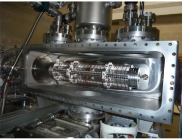
The debuncher prototype design started within the EMILIE (En-hanced Multi-Ionization of short-Lived Ions for Eurisol) project [5]. This debuncher is a linear Paul trap with a characteristic internal radius r0= 15mm and a length of 448 mm. The ions are confined in radial plane by a linear radio-frequency quadrupole (RFQ) structure consisting of 2 couples of rods and axial trapping is achieved by two DC gate electrodes at the axial ends of the debuncher. The scheme of the debuncher is shown onFig. 1and the photo of the debuncher mounted on the HV platform of the test-bench is shown onFig. 2.
The trap geometry is inspired from the ISOLDE ion COOLer (IS-COOL) [6], although in contrast to ISCOOL, the structure of the de-buncher is open, permitting an efficient pumping of the trapping volume, in order to avoid charge recombination of the highly charged ions with the residual gas. The gate electrodes (seeFig. 1) are made as four cross-positioned fingertips instead of full electrode, as SIMION®[7] simulations showed that collection and the transmission could be sig-nificantly increased with such a gate electrode geometry. The injection (entrance) DC gate of the debuncher is pulsed: at low potential during the injection period and at high potential during the trapping/extraction phase.
The DC electrode segments in the trapping region are placed inside the debuncher as it is shown in Fig. 1. These segments allow to increase the potentials inside the debuncher and to eject the ions out
https://doi.org/10.1016/j.nima.2018.11.043
Received 7 August 2018; Received in revised form 23 October 2018; Accepted 9 November 2018 Available online 23 November 2018
0168-9002/© 2018 The Authors. Published by Elsevier B.V. This is an open access article under the CC BY-NC-ND license (http://creativecommons.org/licenses/by-nc-nd/4.0/).
P. Ujić, J.C. Cam, B.M. Retailleau et al. Nuclear Inst. and Methods in Physics Research, A 918 (2019) 30–36
Fig. 1. Drawings of the debuncher prototype and its main parts. Entrance and exit gate electrodes have cross-shaped fingertips in order to increase the transmission efficiency.
of the debuncher in a controlled manner. In this debunching mode, the extraction gate potential is typically kept to a constant value.
The space charge effects limit the maximum ion density (see for instance the Ref. [8], with respect that the debuncher is a linear Paul trap) which could be estimated as:
𝑁𝑚𝑎𝑥= 1 8 𝑚𝛺2𝜀 0 𝑒2𝑍2 𝑞 2 𝑟 (1)
with 𝑚 as the mass of the ion, 𝑍 — charge state of the ions, 𝑒 — electron charge, 𝛺 = 2𝜋𝜈𝑟𝑓the angular radiofrequency and the 𝑞𝑟is the Mathieu
parameter:
𝑞𝑟=4𝑒𝑍𝑉0
𝑚𝑟2 0𝛺2
(2)
where, 𝑟0 — axis to RF electrode (rod) distance (see Fig. 1). In fact, the maximum ion density is calculated for the value when the by the repulsive electrostatic potential of ions becomes equal to trapping pseudo-potential 𝐷𝑟:
𝐷𝑟=𝑉0
8𝑞𝑟 (3)
The motion in an ideal Paul trap is stable for 𝑞𝑟<0.908. For instance, with 𝑞𝑟∼ 0.5, given 𝑟0= 1.5cm, 𝑉0= 1800V and 𝜈𝑟𝑓= 4800kHz, the ion
capacity of this prototype for Au32+is 1.2 109ions. This is more than high capacity BNL EBIS with 10 A electron gun, which can provide 0.9 109Au32+ions per bunch [9]. Regarding the fact that the full-fledged debuncher will be twice as long as the debuncher prototype and that the trapping parameters can be better adjusted, the trapping capacity could be expected to be even higher.
As it was mentioned, the ions can be also extracted by slowly lowering the extraction gate potential of the EBIS and extracted pulse lengths of ∼100 ms are reported [10]. However, in the slow extraction mode, the duty cycle is smaller since the EBIS cannot perform charge breeding while the ions are extracted. In addition, this mode of extrac-tion results in a higher energy dispersion of the extracted ions of 15– 57 eV q, depending on the trap compensation and extraction time [11]. On the other side, in the case of the extraction i.e. the ejection from a debuncher with the inside electrodes, the ions energy is well defined by the extraction gate potential.
Initial objectives that the prototype were to demonstrate [5]: • a maximum of ± 20% current fluctuation for the debunched beam,
for cycles up to 200 ms;
• an overall efficiency above 50% (∼80% as target value) for the whole process, including injection and debunching, for cycles up to 200 ms;
Fig. 2. The debuncher prototype mounted on the test-bench HV platform.
• in the long run, a pressure in the trap down to 5×10⁻¹²mbar or be-low to avoid sizeable recombination losses during the debunching process.
3. Experimental setup
The debuncher was mounted on the HV platform of the SHIRaC [12] test bench whose scheme is shown inFig. 3. The Li1+ions have been chosen for the test due to their rather low A/q-ratio, close to the one that is usually required for reacceleration in post-accelerators. As an example, the CIME cyclotron at GANIL reaccelerates ions with A/q-ratio below 10. The Li1+beam for the test is produced by a surface ion source with an energy of 5000 eV and beam intensities ranging between 0.1 and 200 nA. Beam bunches, as would be expected out of an EBIS, were emulated by switching on/off the injection DC gate of the debuncher. The beam was injected into the debuncher during a period of 10–20 μs and the extracted ions were detected by a Micro-Channel Plate (MCP) detector. The locally developed (LPC Caen) digital acquisition system FASTER [13] was used for the acquisition of the extracted beam. The ion source and the HV platform of the debuncher were not biased at the same potential. The source, placed outside of the HV cage at the ground potential, had its own power supplies which were used to bias
Fig. 3. Scheme of the SHIRaC test-bench used for the debuncher test. The debuncher was
mounted on the HV platform, instead of the RFQ cooler [12].
Fig. 4. The grouping of the 23 internal electrodes of the debuncher used in the test — see
the text for details. There are 8 groups of DC segment, each with a time-varying HVx potential.
the hot surface emitting ions and an einzel lens for beam focusing. The DC segment were wired in 8 groups (HV1–HV8) — seeFig. 4, each having its own controlled potential.
The trapping of Li+ ions was achieved with RF amplitude of 𝑉 0 = 1800V and a fixed frequency of 𝜈𝑟𝑓= 4800kHz. In that case the Mathieu parameter, Eq.(2), 𝑞𝑟= 0.48 < 0.908assures the stability of the trapping.
The pseudo-potential is 𝐷𝑟= 108V, Eq.(3).
The operation of the debuncher device requires good vacuum condi-tions since losses due to collisions and charge exchange with the residual gas must be avoided. During the test, a pressure of 10−7 mbar was obtained, which did not cause significant losses for up to 1 s for single ionized Li ions injected with a low energy into the trap (∼30 eV). In fact, lithium has very low electronegativity, its first electron ionization energy is 5.4 eV and the second electron ionization energy is 75.6 eV, which minimize the charge exchange probability for Li1+ion at given energy.
4. Methods
The first debunching signals were obtained in the frame of the EMILIE project [5] with Cs ions and the same procedure was repeated in this test. The ion extraction was conducted by successive linear ramp of potentials of the DC segment groups inside the debuncher, starting with the DC segment group at the injection side of the trap and finishing at the extraction side [5]. However, the resulting beam was not continuous but rather a succession of pulses (partially due to low energy spread of injected ions), with even worse characteristics for the lighter Li ions used in this test.
Therefore, another approach of the ion extraction was applied: simul-taneous ramps of potentials were applied to all DC segments inside the trap during the extraction phase, with a time function which is supposed to induce uniform ejection rate of the trapped ions. Mathematically, this function is an inversion of the integral of the axial momentum density distribution of the ions trapped in the debuncher. If there is no ion–ion or ion–residual gas interactions inside the debuncher, the ion
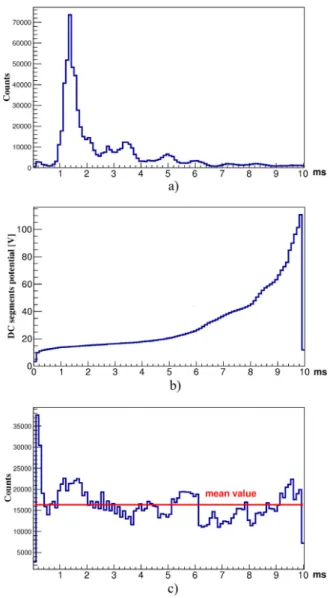
Fig. 5. (a) The energy distribution obtained by linearly increasing the DC potential of
the inner electrodes (b) inverse integral distribution (inverse function) of the response obtained in step (a), (c) the uniform beam extracted using the inverse function for the potential ramp.
axial momentum distribution effectively corresponds to the ion energy distribution.
The axial momentum distribution of the trapped ions can be probed by simultaneous linear increase of the potentials of all the DC segment electrodes. Then the integral distribution function is calculated, whether analytically or numerically, and then the inverse function is made by a simple exchange of the axis coordinates. By applying the inverse integral distribution function (hereafter called inverse function) to all the groups of segments, it is possible to uniformly extract the ions from the debuncher.
Effectively, the inverse function increases the potential ramps in inverse reciprocity to the axial momentum distribution i.e. it ejects more swiftly the ions with momenta for which the ion density is low and more slowly ions with momenta for which the ion density is high. As a consequence, the number of ejected ions per unit of time is in principle uniform.
Principles of this method are described in more details by Lapierre, 2016 [14], with respect to the fact that the method described by Lapierre is described for the ion extraction by lowering the potential of the extraction gate and in this case by linearly increasing the DC potential of the inner electrodes. Example of the method is given inFig. 5: by
P. Ujić, J.C. Cam, B.M. Retailleau et al. Nuclear Inst. and Methods in Physics Research, A 918 (2019) 30–36
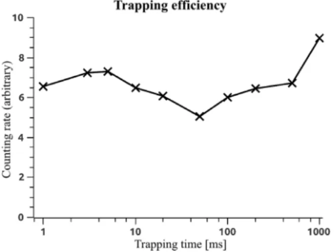
Fig. 6. The trapping efficiency test for Li+ions with a lower ion energy (30 eV) showed that there is no significant losses for trapping durations as long as 1 s.
ramping the potential of all segments linearly in time, from 0 V to 120 V during the trapping time of 10 ms, the energy or more precisely the axial momentum distribution was obtained (inset (a) ofFig. 5). The corresponding numerically calculated inverse function is shown in the inset (b) and the beam debunched with that inverse function in the inset (c).
During the experiment, it was noticed that the beam current at the debuncher exit in the shooting-through mode was not stable. Namely, the extracted beam current would gradually decrease and then suddenly recover, coming back to the original value. Very qualitatively, the frequency of these oscillations depended on the beam intensity, i.e. the higher beam intensity caused the higher oscillation frequencies, although these two quantities were not found to be completely propor-tional. Such behaviour was attributed to successive beam charging and discharging events in the debuncher. The problem was neither localized, nor resolved during the experiment, however lower beam intensities of
<1 nA, provided acceptable conditions for the experiment.
5. Results
5.1. The trapping efficiency test
A trapping efficiency test of Li1+ ions was conducted with an injection energy into the trap with a nominal energy of 30 eV and a extraction gate potential of 230 V. During trapping, the entrance gate potential was hold at 600 V. The extraction in this test was performed by dropping the extraction gate potential to 0 V.
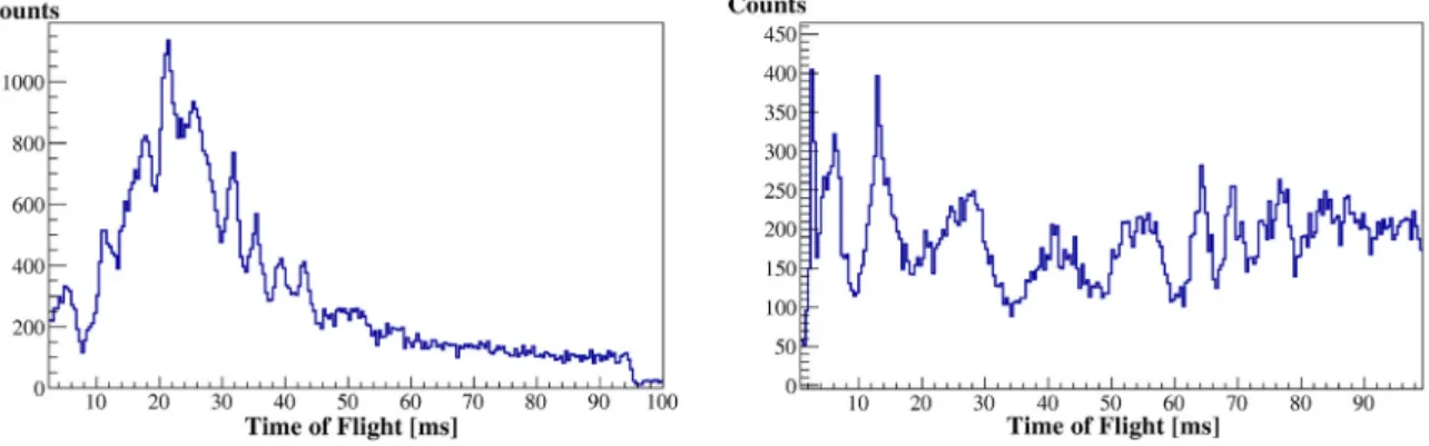
As it can be seen inFig. 6, no losses were noticed for trapping times up to 1 s. The variation of the extracted ion intensity can be attributed to the already noticed fluctuations of the Li beam coming from the ion source, or potentially due to charging/discharging of certain parts in the debuncher being hit by the deflected beam. The measurement uncertainty was significantly smaller than the beam intensity variation. It was noticed that the axial momentum of the trapped ion cloud was being reduced with the trapping time, while its time-of-flight distribution width was increasing — seeFig. 7. The SIMION simulations with the simplified model of elastic collisions between ions and the atoms of the remnant gas (nitrogen) at the room temperature showed that due to collisions the axial momentum is redistributed towards the transversal direction, which explains longer time of flight (ToF) for longer trapping periods. The momentum redistribution can occur due to the ion–ion interaction, as well.
For different ion optics setups, the injection efficiency was estimated to vary from 18% to 30%. Such low injection efficiency is a consequence of the fact that the optics of the SHIRaC workbench was not fully adapted to the debuncher. Injection efficiencies of >85% were simulated in optimized conditions.
Fig. 7. Time of flight (ToF) distributions for different trapping times. ToF was not
calibrated, thus it should be taken only in a sense that the ToF differences are correct, however the offset and thus the absolute ToF is not accurate.
5.2. The debunching
The procedure explained in Section4. was used for the debunching. In addition to the 10 ms debunching period, already presented in Sec-tion4. the procedure was tested for the 100 ms and 800 ms debunching periods.
Due to the instabilities already mentioned in the case of the 10 ms period, the axial momentum distribution of Li ions drifted more or less rapidly with time. The uniform beam extraction for trapping times of 100 ms proved to be more difficult than for the other periods.
By comparing left-hand parts ofFigs. 8and9, it can be noticed that the axial momentum distribution is not stable, neither by form, nor by position, which complicates the uniform extraction, whereby the time difference between these two runs is only 25 min. The process of the inverse function calculation and its loading to the potential generator controlling the DC segment groups was taking around 20 min. Thus, at the moment of the appliance of the inverse function, it was not optimal anymore due to the change of the energy distribution occurring during the preparation of the inverse function.
Thus, a controlled variation on the HV platform ground is introduced in order to induce a controlled energy dispersion, which could smear out and therefore decrease the influence of the parasitic potential and intensity variations. A potential generator with periodic sinh(t2) function was connected to the HV platform ground in order to partially mimic an approximately Gaussian energy distribution of the injected beam of 15–57 eV q [11]. The peak to peak amplitude of the generated sinh(t2) function potential was ∼12 V, with an average of 6 V and the period of ∼1.2 μs. The applied potential was synchronized with the injection period.
The introduction of the potential generator to the ground potential of the HV platform could not completely mask the influence of the potential variations, thus the beam intensity variations were 30%. For longer trapping times, the uniform beam extraction was proved to be easier (seeFig. 10), observing that the beam intensity variations that were induced practically only by the aforementioned instabilities smear out on longer time scales due to the ion momentum redistribution. The ion momentum redistribution occurs due to the collisions with the residual gas and/or the ion–ion interaction, whereby the initial axial momentum of the Li ions is redistributed to its radial component. Thus, the average ToF of ions is getting longer proportionally to the trapping time as well as the ToF distribution is getting wider. SIMION simulations with a simple model of hard sphere elastic scattering, between the Li ions and the residual gas, confirmed the initial redistribution of the momentum. Thus, in the case of 800 ms debunching, it can be observed that the ion axial momentum distribution function shown inFig. 10
(left-hand) is practically flat.
Nonetheless, the dynamical redistribution of the axial momentum of the Li ions introduce a nonlinearity in the application of the inverse
Fig. 8. First 100 ms debunching run: The axial momentum distribution scanned by linear ramp potential during the trapping period of 100 ms (left-hand). The beam extracted by the
inverse integral function (right-hand).
Fig. 9. Second 100 ms debunching run: The axial momentum distribution scanned by linear ramp potential during the trapping period of 100 ms (left-hand). The beam extracted by the
inverse integral function (right-hand). Although this run was recorded only 25 min after the previous one (Fig. 8), a significant difference of the distribution is visible.
Fig. 10. 800 ms debunching: The axial momentum distribution scanned by linear ramp potential during the trapping period of 800 ms (left-hand). The beam extracted by the inverse
function (right-hand).
distribution method, i.e. the energy distribution does not vary linearly with time for a linear ramp of potentials. This effect can partially explain the non-uniformity of the intensity of the extracted beam and it implicates that it is necessary to improve the vacuum conditions.
In the case of the 800 ms debunching period, the background, mostly the noise, was not negligible in contrast to the shorter trapping times (100 ms and less). It was therefore necessary to subtract the background in order to obtain the correct inverse distribution. The background is estimated using the data in the period between two debunching cycles (between 800 and 1000 ms). The background was subtracted under the assumption that it is uniform, which is not necessarily correct and such removal of the background could have introduced an additional non-linearity in the extracted beam intensity.
During the test, it was also demonstrated that it is possible to perform simultaneous beam extraction and beam injection with this debuncher prototype. This was possible due to the flexible potential arrangement of the DC segment groups. The scheme of the process is shown inFig. 11. The DC group segments are forming three principle parts, each of them connected to its own potential: 1. Main buffer (group of DC segments from HV1 to HV5), 2. Separator (HV6), 3. Auxiliary buffer (HV7 and HV8). During the injection period, the injection electrode potential 𝑉inj and those of all the segments of the main buffer are at 0 V. The separator (HV6) is at its maximum potential and the auxiliary buffer electrodes (HV7 and HV8) are increasing their potential, whereby the ions in the auxiliary buffer trapped during the previous sequence are ejected out of the debuncher.
P. Ujić, J.C. Cam, B.M. Retailleau et al. Nuclear Inst. and Methods in Physics Research, A 918 (2019) 30–36
Fig. 11. Scheme of the buffer method: The extraction of the auxiliary buffer (HV7 and
HV8) during the beam injection into the main buffer (HV1–HV5), while the separator is dividing the two buffers (a) and the extraction of the main buffer with the separator (HV1–HV6), while certain number of ions remains trapped in the auxiliary buffer (b). See the text for more details.
Fig. 12. The buffer method of simultaneous beam extraction and the beam injection. The
injection of the ion bunch occurred in the period between 18 and 20 ms.
When the injection finish, the 𝑉injjump to its maximum, all the DC segments drop to 0 V (the main buffer, the separator and the auxiliary buffer) and immediately after, the main buffer (HV1–HV5) and the separator (HV6) potentials start to rise, ejecting the ions out of the debuncher — seeFig. 11(b). During this sequence, a certain number of the ions stays trapped in the auxiliary buffer.
When these segments (the main buffer and the separator) reach the extraction potential 𝑉ext, the separator potential (HV6) jumps to its maximum which has to be higher than 𝑉extin order to insure extraction towards the exit. Immediately after, the cycle restarts (Fig. 11(a)): 𝑉inj and the main buffer drop to zero, the auxiliary buffer (HV7 and HV8) starts to increase its potential ejecting the ions. The buffer method was tested successfully and the full debunching is shown onFig. 12.
Only the feasibility of this method was tested: even though the uniform beam extraction with the inverse function is also applicable to the buffers, it was not fully applied in this case. Nevertheless, the ion extraction from the main buffer and the auxiliary buffer are separated in time, which allows a deconvolution of their ion energy distribution.
6. Conclusions
The principles of uniform ion debunching in the EBIS debuncher were successfully demonstrated for trapping times up to ∼1 s. No detectable losses were recorded for trapped ions with injection energies of ∼30 eV and for trapping times up to 1 s. Depending on the ion optics setup the injection efficiency was estimated to be up to 30%, indicating that dedicated ion optics are necessary to increase the ion injection efficiency. The debunching process was additionally delicate because of potential instabilities in the trap. The next steps would be to stabilize potentials such as the platform or ion source potential and thereby
the energy distribution of the ions introduced to the debuncher, in order to improve the uniformity of the debunching signal. Simultaneous injection and capture of a new bunch, during the slow extraction of the previous one is proved feasible. In this condition the debunching process would be essentially uninterrupted, i.e. completely continuous. While eventual space charge limitations have not been experimentally measured, considerations based on the performance of existing RF devices [15] show that the debuncher principle should be safe up to 109/1010ions per bunch, which is well in the limit of the existing EBIS devices.
In summary, the tests of the EMILIE debuncher prototype have permitted an important proof-of-principle of the debuncher concept: the debunching process works and is efficient. In order to transform the prototype into an operational machine that could be used in combina-tion with an EBIS, two elements are presently missing: an optimized ion optics and improved vacuum conditions. It should be noted that even these elements are presently missing, the results of the simulation of dedicated ion optics undertaken during the course of EMILIE, on one side, and the existing ultra-high vacuum technologies used for example in EBIS devices, on the other, give some confidence that these two aspects will not jeopardize the feasibility of the debuncher concept. As such, the proof of principle reported here clearly offers interesting perspectives for such a device to be used in combination with existing or future EBIS sources at ISOL facilities.
Such setup would be of high interest to produce continuous charge bred beams for existing and future EBIS sources used for charge breeding at continuous machines (i.e. cyclotrons or superconducting CW Linacs, which are already in use in numerous labs reaccelerating radioactive ion beams). For such facilities, the debuncher would be an efficient method to drastically reduce the detection and data handling problems caused by the pulsed beam structure of the EBIS. At longer term, the benefit of such a device would be even more obvious for the intense beams to be produced at EURISOL.
Acknowledgements
This project has received funding from the European Union’s Hori-zon 2020 research and innovation programme, France under grant agreement No. 654002. The authors would like to thank Dr Frederik Wenander and Dr. Yorick Blumenfeld for their precious support.
References
[1] M.A. Levine, R.E. Marrs, J.R. Henderson, D.A. Knapp, M.B. Schneider, The electron beam ion trap: A new instrument for atomic physics measurements, Phys. Scr. T22 (1988) 157.
[2] F. Wenander, Charge breeding of radioactive ions with EBIS and EBIT, J. Instrum. 5 (10) (2010) C10004.
[3] C.J. Gardner, et al., Operation of the RHIC Injector Chain with Ions from EBIS, in: Proceedings of IPAC2015, Richmond, VA, USA, 2015, THPF046.
[4] Pierre Delahaye, ECRIS and EBIS charge state breeders: Present performances, future potentials, Nucl. Instrum. Methods Phys. Res. B 317 (2013) 389–394.
[5] P. Delahaye, A. Galatà, J. Angot, J.F. Cam, E. Traykov, G. Ban, L. Celona, J. Choinski, P. Gmaj, P. Jardin, H. Koivisto, V. Kolhinen, T. Lamy, L. Maunoury, G. Patti, T. Thuillier, O. Tarvainen, R. Vondrasek, F. Wenander, Optimizing charge breeding techniques for ISOL facilities in Europe: Conclusions from the EMILIE project, Rev. Sci. Instrum. 87 (2016) 02B510.
[6] H. Frånberg, P. Delahaye, J. Billowes, K. Blaum, R. Catherall, F. Duval, O. Gianfrancesco, T. Giles, A. Jokinena, M. Lindroos, D. Lunney, E. Mane, I. Podadera, Off-line commissioning of the ISOLDE cooler, Nucl. Instrum. Methods Phys. Res. B 266 (19–20) (2008) 4502–4504.
[7] SIMION®, Scientific Instrument Services, Inc., Idaho National Laboratory, USA. [8] R.E. March, J.F.J. Todd, in: J.D. Winefordner (Ed.), Quadrupole Ion Trap Mass
Spec-trometry, Chemical Analysis, in: A Series of Monographs on Analytical Chemistry and its Applications, Series, Wiley, 2005.
[9] J. Alessi, E. Beebe, S. Binello, C. Gardner, O. Gould, L. Hoff, N. Kling, R. Lambiase, R. Lockey, V. LoDestro, M. Mapes, A. McNerney, J. Morris, M. Okamura, A. Pendzick, D. Phillips, A.I. Pikin, D. Raparia, J. Ritter, T. Shrey, L. Smart, L. Snydstrup, C. Theisen, M. Wilinski, A. Zaltsman, K. Zeno, Performance of the new EBIS preinjector, Proceedings of PAC-2011, 2011, THP055.