HAL Id: tel-01988955
https://tel.archives-ouvertes.fr/tel-01988955
Submitted on 22 Jan 2019
HAL is a multi-disciplinary open access
archive for the deposit and dissemination of sci-entific research documents, whether they are pub-lished or not. The documents may come from teaching and research institutions in France or abroad, or from public or private research centers.
L’archive ouverte pluridisciplinaire HAL, est destinée au dépôt et à la diffusion de documents scientifiques de niveau recherche, publiés ou non, émanant des établissements d’enseignement et de recherche français ou étrangers, des laboratoires publics ou privés.
gamma rays
Michal Rąpala
To cite this version:
Michal Rąpala. Study of nuclear fission by spectrometry of the prompt gamma rays. Nuclear Ex-periment [nucl-ex]. Université Paris Saclay (COmUE), 2018. English. �NNT : 2018SACLS390�. �tel-01988955�
Thès
e de doc
torat
CEA-Saclay
NNT: 2018SACLS390
Etude de la fission nucléaire
par spectrométrie des rayons
gamma prompts
Study of nuclear fission by
spectrometry of the prompt
gamma rays
Thèse de doctorat de l’Université Paris-Saclay
préparée à l’Université Paris-Sud
École doctorale n
◦576 : particules hadrons énergie
et noyau : instrumentation, image, cosmos et
simulation (Pheniics)
Spécialité de doctorat : Structure et réactions nucléaires
Thèse présentée et soutenue à Saclay, le 15 octobre 2018, par
M. Michał R ˛
apała
Composition du Jury :
M. Jonathan Wilson Directeur de Recherche (IPN) Président du jury
MmeLouise Stuttgé Directrice de Recherche (IPHC) Rapporteure
M. Igor Tsekhanovich Professeur (CENBG) Rapporteur
M. Mourad Ramdhane Professeur (LPSC) Examinateur
M. Alain Letourneau Ingénieur de Recherche (CEA) Directeur de thèse
M. Thomas Materna Ingénieur de Recherche (CEA) Co-Directeur de thèse
Contents
1 Introduction 1
1.1 History of a discovery . . . 1
1.2 Fission process . . . 3
1.2.1 Liquid Drop Model . . . 3
1.2.2 Scission . . . 4
1.2.3 Fission fragments mass distribution . . . 5
1.2.4 Fission fragments de-excitation . . . 8
1.3 Nuclear reactors . . . 10
1.4 γ-heating process . . . 12
1.5 Fission fragment de-excitation process simulation . . . 14
1.6 Outline . . . 15
2 FIFRELIN Monte-Carlo simulation code 17 2.1 Introduction . . . 17
2.2 Characteristics of primary fission fragments . . . 18
2.2.1 Mass, charge and kinetic energy . . . 18
2.2.2 Spin and parity . . . 20
2.2.3 Excitation energy . . . 21
2.3 De-excitation process . . . 26
2.3.1 Nuclear realization . . . 26
2.3.2 Competition between neutron and γ-ray emission . . . 27
2.4 Spin cutoff models . . . 30
2.4.1 CONSTANT model . . . 30
2.4.2 BSFG model . . . 31
2.5 Level density . . . 33
2.5.1 Constant temperature model . . . 34 I
2.5.2 Fermi gas model . . . 35
2.5.3 Composite Gilbert-Cameron model . . . 36
2.5.4 Hartree-Fock-Bogoliubov . . . 37
2.6 Photon strength functions . . . 37
2.6.1 Introduction . . . 37
2.6.2 Standard Lorentzian model . . . 39
2.6.3 Enhanced Generalized Lorentzian model . . . 40
2.7 Neutron transmission coefficients . . . 42
2.8 Simulation with the FIFRELIN code . . . 42
2.8.1 Elements selection . . . 42
2.8.2 Models and free parameters selection . . . 43
2.8.3 Results comparison . . . 44
3 EXILL experiment 47 3.1 Introduction . . . 47
3.2 EXILL campaign description . . . 47
3.2.1 General information . . . 47
3.2.2 Experiment setup . . . 51
3.2.3 Data preprocessing . . . 56
3.2.4 Detection system efficiency calibration . . . 57
3.3 Triple-γ coincidence method . . . 61
3.3.1 Introduction . . . 61
3.3.2 Triple-γ coincidence requirements . . . 62
3.3.3 γ-γ-γ cube . . . 62
3.3.4 γ-γ-γ cube analysis . . . 63
3.3.5 Limitations of the analysis method . . . 69
4 New EXILL analysis technique 73 4.1 Introduction . . . 73
4.2 Concepts of the new analysis method . . . 74
4.3 Illustration on EXILL data . . . 77
4.4 Semi-automatic spectra fitting process . . . 79
4.4.1 Fitting procedure . . . 79
4.4.2 Detection system response . . . 83
III Contents
4.5.1 Gate slices fitting . . . 87
4.5.2 No contamination . . . 87
4.5.3 Contamination in the horizontal slice . . . 92
4.5.4 Contamination in both slices . . . 94
4.5.5 Contamination anywhere in the plane . . . 95
4.5.6 Other cases . . . 96
4.6 Performance of the new analysis method . . . 98
4.6.1 Motivations of the 142Ba selection . . . 98
4.6.2 Experimental data extraction . . . 99
4.6.3 Analysis results . . . 99
5 Studies on 100Zr 111 5.1 Introduction . . . 111
5.2 EXILL results and comparison with existing data . . . 114
5.2.1 EXILL results . . . 114
5.2.2 Comparison with existing data on 235U(n th, f ) . . . 116
5.2.3 Comparison with existing data on spontaneous fission . . . 117
5.2.4 Discusion based on FIFRELIN simulations . . . 120
5.3 Evolution with the mass of the fission partner . . . 123
5.3.1 EXILL results . . . 124
5.3.2 Long-lived isomers in Te . . . 127
5.3.3 The CONSTANT spin cut-off model . . . 131
5.3.4 The BSFG spin cut-off model . . . 133
5.4 Spin-distribution dependence . . . 135
5.4.1 Selection of the best models in FIFRELIN . . . 135
5.4.2 Influence of the spin-distribution . . . 141
5.4.3 Comparison of the two models . . . 147
5.5 Dependence with the temperature . . . 149
5.6 Summary of the100Zr analysis . . . 155
General conclusions and perspectives 159 Conclusions . . . 159
Perspectives . . . 161
Résumé 171
R.1 Introduction . . . 171
R.1.1 Processus de fission . . . 171
R.1.2 L’échauffement γ . . . 172
R.1.3 Simulation du processus de désexcitation de fragments de fission 173 R.1.4 Plan du document . . . 173
R.2 Le code de simulation Monte-Carlo FIFRELIN . . . 174
R.2.1 Introduction . . . 174
R.2.2 Caractéristiques des fragments de fission primaires . . . 175
R.2.3 Le processus de désexcitation . . . 176
R.2.4 Les différents modèles implémentés dans FIFRELIN . . . 176
R.2.5 Multiplicité des neutrons prompts . . . 177
R.3 L’expérience EXILL . . . 178
R.3.1 Introduction . . . 178
R.3.2 Description de la campagne EXILL . . . 178
R.3.3 Méthode de coïncidence γ-γ-γ . . . 179
R.4 Nouvelle technique d’analyse . . . 181
R.4.1 Introduction . . . 181
R.4.2 Concepts de la nouvelle méthode d’analyse . . . 181
R.4.3 Analyse de 142Ba . . . 183
R.5 Études sur 100Zr . . . 185
R.5.1 Introduction . . . 185
R.5.2 Résultats et interprétation . . . 186
Appendix A 189 A.1 Experimental results - EXILL data analysis . . . 189
A.1.1 134Te . . . 190 A.1.2 92Kr . . . 192 A.1.3 142Ba . . . 194 A.1.4 94Sr . . . 196 A.1.5 140Xe . . . 198 A.1.6 138Xe . . . 200 A.1.7 104Mo . . . 202 A.1.8 130Sn . . . 204
V Contents A.1.9 144Ba . . . 206 A.1.10 γ-ray intensity dependence with different fission bands of the
fission partner . . . 208
Appendix B 211
B.1 Uncertainty calculation . . . 211 B.1.1 Uncertainty on an intensity from gate slices fitting . . . 211
B.1.2 Uncertainty on a background from gate slices fitting . . . 213
B.1.3 Uncertainty on a number of events coming from the desired
γ-transition in the restricted 2D region of the central gate . . . 213 B.1.4 Uncertainty on the absolute efficiency . . . 214
List of Figures
1.1 Scheme of the neutron induced fission of236U [Gön14a]. . . . 3
1.2 (a) Potential energy surface of a deforming nucleus. (b) The potential
energy along the most energetically favorable fission path. The red "x" marks the saddle point [BL80]. . . 4 1.3 Potential energy as a function of deformation. Q is the nucleus potential
energy at the ground state, Sn is the neutron separation energy, EB is
the fission barrier and ∆V is the potential energy difference between
saddle and scission point [Gön14a]. . . 5
1.4 Pre-neutron emission experimental fission fragment mass yield
distribu-tion following 235U(n
th, f ) [Oku+18]. . . 6
1.5 Multimodal and total fission mass distribution following235U(nth, f ) at
neutron energy En=0.5 MeV [Ham+03]. . . 7
1.6 Multimodal fission mass distribution following 235U(n
th, f ) at neutron
energy En=0.5 MeV [Möl+09]. . . 8
1.7 Fission fragments de-excitation scheme with emission of the prompt and
delayed particles [Lem15]. . . 9
1.8 The design of the HTMR-100 generation IV reactor with a complex
reflectors system [Boy15]. . . 12
1.9 Sources of heating in the nuclear reactor as a function of the distance
from the center of the core [Col+13]. . . 13 1.10 Stages in a process of improvement of the generation IV nuclear reactors
simulation. . . 14
2.1 An example of FIFRELIN input data. The pre-neutron emission
dis-tributions of: fission fragment mass yields (top), average kinetic energy
(middle) and its standard deviation (bottom) [Lit+17]. . . 19
2.2 The de-excitation scheme in [E∗, J ] representation [LS10; Lit+17]. . . . 23
2.3 Neutron emission probability as a function of energy E and angular
momentum J of144Ba [Reg13]. . . . . 23
2.4 Temperature ratio law RT(A). The deformation of the fission fragments
is briefly presented by the pictographs above the boundary points [Lit+17]. 25
2.5 Neutron/γ-ray cascade simulated in FIFRELIN with the coupled
ap-proach. (a) shows three regions of the excitation energy with limits. (b) presents two different de-excitation paths: realized only by γ-rays (red)
and with additional neutron emission (green) [Lit+17]. . . 29
2.6 Spin distributions dependence on the spin cutoff value [Lit+17]. . . 31
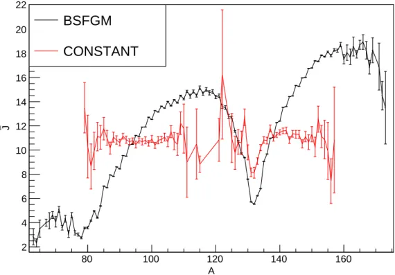
2.7 Average spin ¯J as a function of the fission fragment mass A using the
BSFG or the CONSTANT spin cutoff models. . . 32
2.8 Cumulative number of levels for the 239U compound nucleus. CTM is
used to reproduce the known part of the nuclear level scheme (exper-imental level scheme). The final level scheme sampled by FIFRELIN combines the experimental level scheme at low energy with the theoret-ical level scheme coming from models at high energy. In the presented figure, the CTM spin cutoff model was used in the whole energy range
for the FIFRELIN simulation [Lit+17]. . . 35
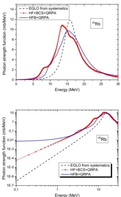
2.9 Photon strength functions of 93Rb calculated with different models:
EGLO, QRPA with Hartree-Fock+Bardeen-Cooper-Schrieffer (HF+BCS+QRPA) and QRPA with Hartree-Fock-Bogoliubov (HFB+QRPA). The upper
plot is a linear-linear representation. The lower plot is a log-log repre-sentation more adapted to see the differences between the models in the energy range involved in fission [Lit+17]. . . 41
3.1 Fission fragments mass distribution coming from the neutron induced
fission of235U and241Pu and the spontaneous fission of 248Cm and 252Cf.
Data taken from [KBM09], graph taken from [Jen+17]. . . 49
3.2 The detector configuration I used during the first reactor cycle of the
EXILL campaign [Jen+17]. . . 52
3.3 The target collimation system layout. It is followed by the target
cham-ber surrounded by the detector array and the beam dump [Jen+17]. . . 53
IX List of Figures
3.5 The detection system absolute efficiency curve fitted with the simple
efficiency Equation 3.6 [Rą15]. The uncertainties on the experimental efficiency points are smaller than the marker size. . . 59
3.6 The detection system absolute efficiency curve fitted with the modified
efficiency Equation 3.7. The absolute efficiency experiment data was corrected for the true coincidence effect. . . 60
3.7 Schematic presentation of the fission fragments de-excitation process.
Fission fragment emits prompt γ-rays in the form of a cascade. The energies of these γ-rays are unique for each nucleus. . . 61
3.8 Prompt γ-ray spectrum without coincidence of 235U(nth, f ) measured
during the EXILL experiment after Compton rejection. . . 65
3.9 Schematic view of gates placement when "double gates" are used. Two gates are placed in the fission fragment A. In the coincidence spectrum one will see the complete de-excitation cascade of its fission partner B. Also cascades of other fission partners will be visible. . . 66 3.10 Schematic view of gates placement when "mixed gates" are used. The
first gate is placed in the fission fragment A, the second one in its fission partner B. In the coincidence spectrum one will not see the complete de-excitation cascade of the fission partner B. Nevertheless, the spectrum will be much cleaner because no cascade of other fission partners will be present. . . 66
3.11 Level scheme of92Kr [RU+00]. The 769.0 keV γ-ray was selected as the
first gate in the presented example. . . 67
3.12 Level scheme of 142Ba [Urb+97]. The 359.5 keV γ-ray was selected as
the second gate in the presented example. . . 67
3.13 Prompt γ-ray spectrum of235U(n
th, f ) in coincidence with the 769.0 keV
γ-transition from92Kr, with the background subtraction. . . . 68
3.14 Prompt γ-ray spectrum of 235U(n
th, f ) in coincidence with the 769.0
keV and 359.5 keV γ-transitions from92Kr and 142Ba, respectively, with
the double subtraction of the background. The γ-rays with the highest intensities emitted by 92Kr and 142Ba can be easily identified. . . . 69
3.15 First gate and background selection with standard γ-γ-γ coincidence
3.16 Second gate and background selection with the standard γ-γ-γ
coinci-dence method. The peak at 199.2 keV comes from the144Ba. . . 70
3.17 Prompt γ-ray spectrum of235U(n
th, f ) in coincidence with the 401.6 keV
and 199.2 keV γ-transitions from90Kr and144Ba, respectively, with the
double subtraction of the background. . . 71
4.1 Schematic representation of the standard way of analyzing the data. To
obtain the intensity of a transition in coincidence with the transitions TAand TB, with energy EAand EB, one builds the spectrum of γ-rays in
coincidence with a small region around (EA, EB), then subtracts γ-rays
in coincidence with the regions around (EA0 , EB) and around (EA, EB0 )
and adds γ-rays in coincidence with a region around (EA0 , EB0 ). . . 75
4.2 Schematic representation of the new way of 2D gate scanning around
(EA, EB). Each square corresponds to a 2D gate with (∆A, ∆B) size. . 77
4.3 2D scan of the gates in the Polish cube. Each dot denotes one pair of
gates. The point at the intersection between the horizontal, the vertical and the diagonal slices (red dot) denotes the exact energies of the initially selected gates. Each number of counts comes from fitting the same γ-ray peak in the particular triple-γ coincidence spectrum. The measured γ-ray is at 475.0 keV in 142Ba. The initial gates are the transition at 769.0 keV in92Kr and the transition at 359.5 keV in142Ba. . . 78
4.4 2D scan of the gates in the GANIL cube. Each dot denotes one pair of
gates. The point at the intersection between the horizontal, the vertical and the diagonal slices (red dot) denotes the exact energies of the initially selected gates. Each number of counts comes from fitting the same γ-ray peak in the particular triple-γ coincidence spectrum. The measured γ-ray is at 352.0 keV in 100Zr. The initial gates were the transition at 212.6 keV in100Zr and the transition at 1279.3 keV in 134Te. . . 79
4.5 All the gated spectra generated with the scan of gates, zoomed on the
γ-ray peak at 475.0 keV in142Ba. The central gate (E
A, EB) is set around
XI List of Figures
4.6 All the gated spectra generated with the scan of gates, zoomed on the
γ-ray peak at 475.0 keV in142Ba. The central gate (EA, EB) is set around
the 769.0 keV transition in 92Kr and the 359.5 keV transition in 142Ba. All γ-ray peaks were found and fitted. Blue triangles indicate the peak positions. . . 81
4.7 Peak positions in all triple-γ coincidence spectra generated with the 2D
scan of gates. The initial gates were the γ-ray at 769.0 keV in92Kr and
the γ-ray at 359.5 keV in 142Ba. All γ-ray peaks were found and fitted
in the region around the desired γ-ray at 475.0 keV in142Ba. Red lines
are the (weighted) averaged energy of peaks. Gate pair 0 is the pair of central gates, gate pairs 1-14 are horizontal gates, gate pairs 15-28 are
vertical gates, 29-42 are diagonal gates, starting from the lowest energy. 82
4.8 All triple-γ coincidence spectra generated with the 2D scan of gates.
The initial gates were the γ-ray at 769.0 keV in 92Kr and the γ-ray at
359.5 keV in142Ba. All γ-ray peaks were found and fitted in the region
around the desired γ-ray at 475.0 keV in 142Ba. The position of each
peak is synchronized in all spectra based on their (weighted) averaged energy from the initial fit. Blue triangles indicate the synchronized peak positions. Green triangles indicate the peak positions from the first fit of the peaks (Figure 4.6). . . 83
4.9 Partial level scheme of 92Zr with some of the transitions populated in
the 91Zr(n, γ) reaction. . . . 84
4.10 Fit function shape used to fit the γ-transition peaks (black curve). It is composed of three Gaussian functions (red, green, blue curves) and, of a smooth step function that models the Compton tail (not represented). The black curve is the final response function. . . 85 4.11 Peak of92Zr at 1405.1 keV used to adjust the new fit function. The red
curve is the fit function. The green curve is the fit function integrated over the bins. Experimental data are in dark blue, almost invisible due to relatively good fit. . . 86
4.12 Histogram visualizing the horizontal (a), vertical (b) and diagonal (c)
slice in the Polish cube. Dark blue lines denote the data (partially
covered by the green lines), red lines denote the fit function and green lines denote the fit function integrated over the single gate size. The fit was performed on the γ-ray transition at 475.0 keV in142Ba. The initial
gates are the transition at 769.0 keV in92Kr and the transition at 359.5
keV in 142Ba. The same peak areas in the form of a cross can be seen in
Figure 4.3. This fit was used in the142Ba analysis is Section 4.6. . . . . 88
4.13 Schematic representation in the case of no contamination. . . 89
4.14 Coincidence matrix built from the fitted peak area at 475.0 keV. Details are explained in the text. . . 90 4.15 Schematic representation in the case of a contaminating peak in the
horizontal slice. . . 92 4.16 Schematic representation in the case of contaminating peaks in the
hor-izontal and the vertical slice. . . 94 4.17 Schematic representation in the case of a contaminating peak anywhere
in the (E1, E2) plane. . . 95
4.18 Schematic representation in the case of a contaminating peak in the vertical slice and another one anywhere in the (E1, E2) plane. . . 97
4.19 Schematic representation in the case of three contaminating peaks: in the vertical slice, in the horizontal slice and the third one anywhere in the (E1, E2) plane. . . 97
4.20 The selection process of the first gate and the background with the standard technique. The gate is put at the γ-transition at 769.0 keV
from92Kr. The horizontal axis is not placed at the zero counts. . . . . 102
4.21 The selection process of the second gate and the background with the standard technique. The gate is put at the γ-transition at 359.5 keV from142Ba. The horizontal axis is not placed at the zero counts. . . 103
4.22 The spectrum without coincidence. The first gate is put at the
γ-transition at 359.5 keV from 142Ba. The horizontal axis is not placed
XIII List of Figures 4.23 The spectrum in simple coincidence with the γ-transition at 359.5 keV
(142Ba) obtained with the standard technique. The second gate is put
at the γ-transition at 769.0 keV from 92Kr. The horizontal axis is not
placed at the zero counts. . . 104 4.24 The tiple-γ coincidence spectrum zoomed at the desired γ-ray at 706.8
keV (142Ba). The selected gates are the γ-transitions at 769.0 keV (92Kr)
and at 359.5 keV (142Ba). The horizontal axis is not placed at the zero
counts. . . 105 4.25 The representation of the region of interest for the γ-transition at 706.8
keV (142Ba). The main gates are the γ-transitions at 769.0 keV (92Kr)
and at 359.5 keV (142Ba). . . 106 4.26 The fits of the region of interest for the γ-transition at 706.8 keV (142Ba)
for all spectra in triple coincidence. The main gates are the γ-transitions at 769.0 keV (92Kr) and at 359.5 keV (142Ba). . . 106 4.27 The fit of the horizontal (a), vertical (b), and diagonal (c) gate slices
for the γ-transition at 706.8 keV (142Ba). The main gates are the
γ-transitions at 769.0 keV (92Kr) and at 359.5 keV (142Ba). . . 107
4.28 91Kr level scheme taken from [RU+17a]. . . . 108
5.1 Level scheme of 100Zr built with the data coming from the spontaneous
fission of252Cf [Hwa+06]. . . . 113
5.2 Level scheme of100Zr built with the data coming from the EXILL
experi-ment. Transition energies (in keV) and transition intensities (normalized to the 212.5 keV transition) are indicated on each arrow. . . 115
5.3 Ratio of γ-transition intensities in 100Zr between the EXILL and the
252Cf data [Hwa+06]. Fitted value is equal to 0.597(23). . . . 119
5.4 Partial level scheme of100Zr built with the data coming from the FIFRE-LIN simulation using EGLO photon strength functions, CGCM level density model and CONSTANT spin cut-off model. Transition energies (in keV) and transition intensities (normalized to 100 on the 212.5 keV transition) are indicated on each arrow. Only the transitions with an intensity higher than 3.5% are shown. . . 121 5.5 The level scheme of 132Te from [Hop+72]. . . 124
5.6 The level scheme of 133Te from [Bha+01]. Level energies are expressed relative to zero for the 11/2− isomeric state which is at 334.26 keV. . . 124 5.7 Level scheme of 134Te from [Sah+01]. . . 125
5.8 Evolution of γ-transition intensities in 100Zr with Te mass number
ob-tained from the EXILL experiment data. The dashed lines show the fits with a first degree polynomials function. . . 126 5.9 Schematic view of gates placement when "mixed gates" are used and
a nanosecond isomer is present. The first gate is placed in the fission fragment A below the long-lived isomer, the second one in its fission partner B. One can obtain correct intensities of the prompt γ-rays in both fission fragments A and B (marked in green). . . 128 5.10 Schematic view of gates placement when "double gates" are used and
a nanosecond isomer is present. Two gates are placed in the fission fragment A, both below the nanosecond isomer. One can obtain correct intensities of the prompt γ-rays in the fragments B (marked in green). . 128 5.11 Schematic view of gates placement when "double gates" are used and
a nanosecond isomer is present. Two gates are placed in the fission fragment B. One cannot obtain correct intensities of the prompt γ-rays in fragments A (marked in red) because the intensities of the γ-transitions below the long-lived state is reduced due to used acceptance time window.130 5.12 Schematic view of gates placement when "mixed gates" are used and
a nanosecond isomer is present. The first gate is placed in the fission fragment A above the long-lived isomer, the second one in its fission partner B. One cannot obtain correct intensities of the prompt γ-rays in fragments A (marked in red) because the intensities of the γ-transitions below the long-lived state is reduced. . . 130
5.13 Evolution of simulated γ-transition intensities in 100Zr with Te mass
number when the CONSTANT spin cut-off model is used. . . 132
5.14 The process of neutron evaporation superposed on the100Zr level density ρ(E, J ). The gray line marks the mean value of the level density as a function of the excitation energy taken from RIPL-3. . . 133 5.15 Evolution of the simulated γ-transition intensities in100Zr with Te mass
XV List of Figures
5.16 Light fragment neutron energy in the 100Zr cascade when the CTM
model is used. . . 139
5.17 Light fragment neutron energy in the 100Zr cascade when the CGCM
model is used. . . 139 5.18 Initial distribution of excitation energy (XE) and spin (J ) for light
fission fragments when the CONSTANT spin cut-off model is used and ¯
σL= ¯σH = 9.5. . . 142
5.19 Evolution of simulated γ-transition intensities in 100Zr depending on
the spin cut-off value. The CONSTANT spin cut-off model was used. Dashed lines show intensity values from the EXILL experimental data, dotted lines errors on them. . . 143 5.20 χ2values containing main band γ-ray transitions in 100Zr for FIFRELIN
simulations with different spin cut-off values. In each simulation ¯σLwas
equal to ¯σH. . . 144
5.21 χ2value containing main band γ-transitions in100Zr for FIFRELIN
sim-ulations with different scaling factor values (fσ). . . 145
5.22 Initial distribution of excitation energy (XE) and spin (J ) for light
fission fragments when the BSFG spin cut-off model is used, fσ = 1.8
and RmaxT = 1.23. . . 146
5.23 Initial distribution of excitation energy (XE) and spin (J ) for light
fission fragments when the BSFG spin cut-off model is used, fσ = 1.15
and Rmax
T = 1.23. . . 146
5.24 Evolution of simulated γ-ray transition intensities in100Zr depending on
the spin cut-off value. The BSFG spin cut-off model was used. Dashed lines show intensity values from the EXILL experimental data, dotted lines errors on them. . . 147 5.25 ¯νL and ¯νH obtained with FIFRELIN simulations as a function of RmaxT
and for different RminT . Full lines show ¯νL. Dashed lines show ¯νH. Red
lines show the experimental values. Only 3 different RminT values are
presented: minimum (0.5), maximum (0.95) and one from the analysis of the BSFG spin cut-off model (0.75). . . 150 5.26 Prompt-neutron multiplicity sawtooth as a function of a fission fragment
mass number, coming from the published experimental data [Bat+05; MRC67; Nis+98; Vor+10]. . . 151
5.27 ¯ν(100) obtained with FIFRELIN simulations as a function of RmaxT and
for different RminT . Only 3 different RminT values are presented: minimum
(0.5), maximum (0.95) and one which was used in the previous analysis of the BSFG spin cut-off model (0.75). Dashed, red lines mark minimal and
maximal ¯ν(100) coming from the published experimental data (Figure
5.26). . . 152
5.28 Temperature curve showing the relation between Rmin
T and RmaxT . Dashed,
red line marks a position of 100Zr. . . 152
5.29 χ2 value containing main band γ-transitions in100Zr for FIFRELIN sim-ulations with different scaling factor values (fσ) for RmaxT = 1.0. . . 153
5.30 Initial distribution of excitation energy (XE) and spin (J ) for light
fission fragments when the BSFG spin cut-off model is used, fσ = 1.2
and Rmax
T = 1.0. . . 155
R.1 Représentation schématique de la méthode standard d’analyse des don-nées. Pour obtenir l’intensité d’une transition en coïncidence avec les transitions TA et TB, avec l’énergie EA et EB, on construit le spectre
des rayons γ en coïncidence avec une petite région autour de (EA, EB),
puis on soustrait les rayons γ en coïncidence avec les régions autour de (EA0 , EB) et autour de (EA, EB0 ) et ajoute les rayons γ en coïncidence
avec une région autour (EA0 , EB0 ). . . 183 R.2 Représentation schématique de la nouvelle façon de scanner les portes
2D autour de (EA, EB). Chaque carré correspond à une porte 2D avec
la taille (∆A, ∆B). . . 184
A.1 Level scheme of 134Te from [Sah+01]. . . 190
A.2 χ2 value containing γ-transitions: 115.7 keV, 297.1 keV, 706.3 keV, 978.5
keV, 2322.0 keV in 134Te, for the FIFRELIN simulations with different
scaling factor values (fσ). The χ2 was calculated according to Equation
5.1. Models and free parameters set used in the simulations: EGLO photon strength functions, CTM level density model, BSFG spin cut-off model, Rmin
T = 0.75, RmaxT = 1.23. . . 190
A.3 Evolution of γ-transition intensities in 92Kr with Ba mass number
ob-tained from the EXILL experiment data. Lines show the fits with the constant function. . . 193
XVII List of Figures
A.4 χ2 value containing γ-transitions: 359.7 keV, 475.3 keV, 631.5 keV,
693.4akeV in142Ba, for the FIFRELIN simulations with different scaling
factor values (fσ). The χ2 was calculated according to Equation 5.1.
Models and free parameters set used in the simulations: EGLO photon strength functions, CTM level density model, BSFG spin cut-off model, Rmin
T = 0.75, RmaxT = 1.23. . . 194
A.5 Evolution of γ-transition intensities in 142Ba with Kr mass number ob-tained from the EXILL experiment data. Lines show the fits with the constant function. . . 194
A.6 Level scheme of 94Sr from [RU+09]. . . 196
A.7 Evolution of γ-transition intensities in 94Sr with Xe mass number ob-tained from the EXILL experiment data. Lines show the fits with the constant function. . . 197
A.8 Level scheme of 140Xe from [Ham+97]. . . 198
A.9 Evolution of γ-transition intensities in 140Xe with Sr mass number ob-tained from the EXILL experiment data. Lines show the fits with the constant function. . . 198
A.10 Level scheme of 138Xe from [Kor+00]. . . 200
A.11 Level scheme of104Mo from [Jon+05]. Different fission bands are denoted by the numbers in brackets at the top of each band. . . 202
A.12 Level scheme of 90Kr from [RU+17b]. . . 206
A.13 Level scheme of 144Ba from [Urb+97]. . . 206
A.14 Level scheme of 87Kr from [dAn07]. . . 208
List of Tables
2.1 Simulated numbers of γ-rays emitted by 100Zr at the selected energies.
Each simulation used a different random seed value thus different set of the nuclear realizations. Transition energies were taken from RIPL-3 database. . . 27 2.2 Models and free parameters used to simulate235U(nth, f ). . . 44
2.3 Dependence of the prompt-neutron multiplicity values on the number of
simulated events. In both simulations, models and free parameters are the same, see Table 2.2. The discrepancy between the simulated and
experimental multiplicities are less than 1% for both simulations. . . . 44
3.1 Experiments performed during the EXILL campaign. The experiments
marked in bold were analyzed in this work [Jen+17]. . . 48
4.1 Relative intensities (Iγ) of the γ-ray transitions (keV) in 142Ba,
normal-ized to the 4+1 → 2+
1 transition (475.0 keV). 248Cm data comes from
[Urb+97]. EXILL data analyzed with the standard technique (EXILL data old) comes from [Rą15]. The fission partner of142Ba for the EXILL
data analyzed both with the standard and the new technique (EXILL
data new) was92Kr, for [Urb+97] it was a complementary Zr fragment.
To the intensities measured with the standard technique from the EXILL data additional 10% uncertainty has to be added due to the uncertainty of the background selection. . . 101
5.1 The most produced elements in the235U(n
th, f ) reaction and their charge
yields according to JEFF-3.3. . . 112 XIX
5.2 Relative intensities (Iγ) of the γ-ray transitions measured in 100Zr
ob-tained in this work at EXILL compared to the ones obob-tained at CIRUS [Muk+12]. Intensities are normalized on the 352.0 keV transition to 100.
In both experiments the235U(n
th, f ) was analyzed. . . 116
5.3 Relative intensities (Iγ) of the γ-ray transitions (keV) in 100Zr,
normal-ized to the strongest transition (212.5 keV). 252Cf data coming from
[Hwa+06],248Cm data coming from [Dur+95]. The fission partner of
100Zr was not specified for [Hwa+06] and [Dur+95]. . . 118
5.4 Models used to simulate 235U(n
th, f ) and 252Cf(sf ). . . 120
5.5 Parameters used to simulate 235U(nth, f ) and 252Cf(sf ). . . 120
5.6 Relative intensities (Iγ) of the γ-ray transitions (keV) in 100Zr,
nor-malized to the strongest transition (212.5 keV). Data coming from the
FIFRELIN simulation of the 235U(n
th, f ) and 252Cf(sf ). The analyzed
fission fragment pairs are100Zr -134Te (235U(n
th, f )),100Zr -150Ce (252Cf(sf )(2n))
and 100Zr - 148Ce (252Cf(sf )(4n)). The model/parameter setup used in
these simulations can be found in Tables 5.4 and 5.5. . . 122 5.7 χ2values containing main band γ-transitions in100Zr for FIFRELIN
sim-ulations utilizing different models. The best results for the CONSTANT and BSFG spin cut-off models are written in bold text. . . 137 5.8 Relative intensities (Iγ) of the γ-ray transitions (keV) in 100Zr,
normal-ized to the strongest transition (212.5 keV). Comparison of the EXILL experimental data with the simulations using the EGLO and HFB pho-ton strength functions, the CTM level density model and the CON-STANT spin cut-off model, without collective neutron behavior. These simulations give the correct neutron multiplicity. . . 138 5.9 Relative intensities (Iγ) of the γ-ray transitions (keV) in 100Zr,
normal-ized to the strongest transition (212.5 keV). Comparison of the EXILL
experimental data with the simulations having the lowest χ2 value,
us-ing CONSTANT (¯σL=¯σH=9.5) and BSFG (fσ=1.8) spin cut-off models
and the CTM level density model. These simulations give the correct neutron multiplicities (¯νL, ¯νH, ¯νT ot). . . 140
5.10 Parameters used to simulate 235U(n
th, f ) with the CONSTANT spin
cut-off model giving the best agreement with the EXILL data for the γ-intensities and the correct ¯νT ot. . . 141
XXI List of Tables
5.11 Parameters used to simulate 235U(nth, f ) with the BSFG spin cut-off
model giving the most accurate intensities and correct ¯νT ot. . . 144
5.12 Relative intensities (Iγ) of the γ-ray transitions (keV) in100Zr,
normal-ized to the strongest transition (212.5keV). Comparison of the EXILL experimental data with the simulations scanning the spin cut-off value or fσ which gives the lowest χ2. . . 148
5.13 Average prompt-neutron multiplicities for the simulations which give the
lowest χ2 value. For CONSTANT, the spin cut-off parameter is equal
to 5.5. For BSFG, fσ is equal to 1.15. The adopted experimental values
are taken from [Nis+98]. . . 149 5.14 Relative intensities (Iγ) of the γ-ray transitions (keV) in100Zr,
normal-ized to the strongest transition (212.5 keV). Comparison of the EXILL experimental data with the simulations using BSFG which give the low-est χ2 value for different RmaxT . . . 154
A.1 Relative intensities (Iγ) of the γ-ray transitions (keV) in 134Te,
nor-malized to the 2+1 → 0+
1 transition (1279.3 keV). 248Cm data comes
from [Sah+01]. The fission partner of 134Te for the EXILL data was
100Zr, for [Sah+01] it was 110Ru, 111Ru or 112Ru. For 248Cm data,
ex-cept for the weakest lines, the intensities should be accurate within 20% [Sah+01]. Models and free parameters set used in the FIFRELIN sim-ulation: EGLO photon strength functions, CTM level density model, BSFG spin cut-off model, RminT = 0.75, RmaxT = 1.23, fσ = 1.5
(opti-mized, see Figure A.2). *The γ-transition intensities were not corrected to take into account that the excited state at 1692.1 keV is long-lived (164 ns). . . 191 A.2 Relative intensities (Iγ) of the γ-ray transitions (keV) in 92Kr,
normal-ized to the 2+1 → 0+
1 transition (769.0 keV). The fission partner of 92Kr
for the EXILL data and the FIFRELIN data was 142Ba. Models and
free parameters set used in the FIFRELIN simulation: EGLO photon strength functions, CTM level density model, BSFG spin cut-off model, Rmin
T = 0.75, RmaxT = 1.23, fσ = 1.8. These parameters were used in
the reference FIFRELIN simulation (Table 5.7) which gave the correct prompt-neutron multiplicity. . . 192
A.3 Relative intensities (Iγ) of the γ-ray transitions (keV) in 142Ba,
normal-ized to the 2+1 → 0+1 transition (395.5 keV). 248Cm data comes from
[Urb+97]. The fission partner of 142Ba for the EXILL data measured
with the new analysis technique (EXILL data) was 92Kr, for [Urb+97]
it was a complementary Zr fragment. Models and free parameters set used in the simulations: EGLO photon strength functions, CTM level
density model, BSFG spin cut-off model, Rmin
T = 0.75, RmaxT = 1.23, fσ
= 1.05 (optimized, see Figure A.4). . . 195
A.4 Relative intensities (Iγ) of the γ-ray transitions (keV) in 94Sr,
normal-ized to the 4+1 → 2+
1 transition (1308.9 keV). 248Cm data comes from
[RU+09]. The fission partner of94Sr for the EXILL data measured with
the new analysis technique (EXILL data) was 140Xe. [RU+09] results
were obtained from spectra doubly gated in94Sr on different γ-ray peaks.
Models and free parameters set used in the simulations: EGLO photon strength functions, CTM level density model, BSFG spin cut-off model, RminT = 0.75, RmaxT = 1.23, fσ = 1.8. . . 197
A.5 Relative intensities (Iγ) of the γ-ray transitions (keV) in 140Xe,
nor-malized to the 4+1 → 2+1 transition (457.4 keV). 252Cf data comes from [Ham+97], intensity uncertainties are around 15%. The fission partner
of 140Xe for the EXILL data measured with the new analysis technique
(EXILL data) was 94Sr, for [Ham+97] it was a complementary Ru
frag-ment. Models and free parameters set used in the simulations: EGLO photon strength functions, CTM level density model, BSFG spin cut-off model, Rmin
T = 0.75, RmaxT = 1.23, fσ = 1.8. . . 199
A.6 Relative intensities (Iγ) of the γ-ray transitions (keV) in138Xe,
normal-ized to the 8+1 → 6+
1 transition (729.6 keV). The fission partner of 138Xe
for the EXILL data and the FIFRELIN data was 96Sr. Models and
free parameters set used in the FIFRELIN simulation: EGLO photon strength functions, CTM level density model, BSFG spin cut-off model, Rmin
XXIII List of Tables A.7 Relative intensities (Iγ) of the γ-ray transitions (keV) in 104Mo,
normal-ized to the 2+1 → 0+1 transition (192.0 keV). 248Cm data comes from
[Gue+96; Smi+02]. The fission partner of 104Mo for the EXILL data
measured with the new analysis technique (EXILL data) was130Sn, for
[Gue+96] it was 140Xe. [Smi+02] results were obtained from spectra
doubly gated in 104Mo on different γ-ray peaks. Models and free
pa-rameters set used in the simulations: EGLO photon strength functions,
CTM level density model, BSFG spin cut-off model, Rmin
T = 0.75, RmaxT
= 1.23, fσ = 1.8. . . 203
A.8 Relative intensities (Iγ) of the γ-ray transitions (keV) in 130Sn,
normal-ized to the (4+1) → (2+1) transition (774.4 keV). The fission partner of
130Sn for the EXILL data measured with the new analysis technique
(EX-ILL data) was104Mo. Models and free parameters set used in the
sim-ulations: EGLO photon strength functions, CTM level density model, BSFG spin cut-off model, RminT = 0.75, RmaxT = 1.23, fσ = 1.8. . . 204
A.9 Relative intensities (Iγ) of the γ-ray transitions (keV) in 144Ba,
normal-ized to the 4+1 → 2+
1 transition (330.7 keV). 248Cm data comes from
[Urb+97]. The fission partner of 144Ba was 90Kr gated at 655.6 keV.
Most of the transitions from [Urb+97] were measured in the spectra
double-gated in144Ba. Models and free parameters set used in the
sim-ulations: EGLO photon strength functions, CTM level density model,
BSFG spin cut-off model, Rmin
T = 0.75, RmaxT = 1.23, fσ = 1.8. . . 207
A.10 Relative intensities (Iγ) of the γ-ray transitions (keV) in 146Ba,
normal-ized to the 4+1 → 2+1 transition (332.7 keV). The fission partner of146Ba
was87Kr. In both presented measurements one of the gates was at 181.1
keV (2+1 → 0+1) transition in 146Ba, second either at 1577.5 keV or at
1419.8 keV in 87Kr. Transitions at 1577.5 keV and at 1419.8 keV go to
the ground state of87Kr but they belong to different bands, see Figure
Chapter 1
Introduction
According to Encyclopædia Britannica, the most basic definition of nuclear fission is: subdivision of a heavy atomic nucleus, such as that of uranium or plutonium, into two fragments of roughly equal mass. The process is accompanied by the release of a large amount of energy [Ste18]. In plain words, it is a split of an atomic nucleus into smaller parts (at least two lighter nuclei).
1.1
History of a discovery
In 1938, Otto Hahn, Lise Meitner, and Fritz Strassmann began performing an exper-iment during which uranium was bombarded with neutrons. After chemical analysis, O. Hahn concluded that some of the products of this bombardment was barium. L. Meitner interpreted it as an evidence of nuclear fission - split of an uranium nucleus into two lighter nuclei. She explained this behavior with the mass disappearance phe-nomenon. The combined mass of the two division products would be lighter than the original uranium nucleus by about one-fifth of the proton mass. This missing mass,
according to Einstein’s formula E = mc2, would be equal to 200 MeV. L. Meitner
pre-dicted that about this amount of the repulsion energy would be needed to drive apart two nuclei after separation [MF39]. In this way, she created a theory which matched the observed phenomenon. The results were published in 1939 [MF39] and, in 1944, O. Hahn was granted the Nobel Prize in Chemistry for the discovery of the fission of heavy nuclei [Nob].
This discovery would not have been possible without earlier studies on the atom structure and radioactivity. Henri Becquerel in 1896 discovered radioactivity, while
working with phosphorescent materials. The uranium salts caused a blackening of the plate covered with a phosphorescent material. He identified it as a sort of invisible radiation. His further studies along with Pierre Curie and Maria Skłodowska Curie showed that the observed radioactivity was more complex than already known X-rays. In 1903, they received the Nobel Prize in Physics for the discovery and research on spontaneous radioactivity.
In 1900, Paul Villard observed a powerful ray while studying radiation emitted
from radium. But only in 1903, Ernest Rutherford concluded that these rays are
fundamentally different from already known types and he called them γ-rays.
In 1911, Ernest Rutherford presented a model which assumed that an atom consists of a tiny, dense and positively charged nucleus of protons and it is surrounded by orbiting, negatively charged electrons. In 1913, Niels Bohr developed this model by adding the quantum behavior of electrons creating the Bohr model.
Another event which led to the nuclear fission detection was the discovery of the neutron in 1932 by James Chadwick [Cha32]. He used the energetic alpha particles emitted from polonium to irradiate beryllium which led to the emission of a strongly penetrating radiation. He rejected the hypothesis that the observed effect was caused by γ-rays and proposed a new particle named neutron - uncharged, having a mass almost the same as the proton. He received the Nobel Prize in Physics for this discovery in 1935. Enrico Fermi quickly (1934) used the new particle to conduct an experiment on bombarding uranium with neutrons. He claimed to create new elements with 93 and 94 protons. Not all scientists were convinced with his discovery and later a very similar experiment was used to discover the nuclear fission.
In 1933, Leó Szilárd proposed the concept of a nuclear chain reaction, and in 1934 together with Enrico Fermi, patented the concept of a nuclear reactor (a chain reaction pile). After the discovery of the nuclear fission, Frédéric Joliot, Hans Von Halban and Lew Kowarski proved in 1938 that a nuclear chain reaction is possible by neutron multiplication in uranium. In 1939, they filed three patents: two describing power production from a nuclear chain reaction and one using it to create a bomb. This opened a road to harness the enormous amounts of the energy released during the nuclear fission for both peaceful and military purposes.
3 1.2. Fission process
1.2
Fission process
Nowadays, our knowledge about the nuclear fission is much wider. Our interest in the process reaches much deeper than a simple energy exploitation and we try to understand and study all the phenomena which lead to fission and that occur after
scission. In this work we analyze data coming from the thermal neutron induced
fission of 236U (235U(n
th, f ) reaction).
1.2.1
Liquid Drop Model
The neutron induced fission process starts with the creation of the fissioning system. A
nucleus (235U) in the ground state captures a neutron and forms a compound nucleus
(236U). Its lifetime is close to a femtosecond [Vor+77]. The compound nucleus vibrates
and deforms, obtaining a configuration where two groups of nucleons are connected by a neck, see Figure 1.1.
Figure 1.1: Scheme of the neutron induced fission of 236U [Gön14a].
The deformation of the compound nucleus rises and it reaches the saddle point -the critical deformation of no return to -the mono-nucleus. At this point -the compound nucleus overcomes the potential barrier called "fission barrier".
The concept of the fission barrier was proposed by Bohr and Wheeler (1939). They created the theory of the electrically charged liquid drop - Liquid Drop Model (LDM). In LDM the nucleus is treated as a drop of very dense, incompressible fluid. The nucleons behave like the molecules in a drop of liquid.
In LDM the nuclear "fluid" is assumed to be incompressible thus when the liquid drop becomes deformed only the surface and the Coulomb energy are affected. The surface energy takes into account that the nucleons at the surface are less bounded
than the interior nucleons of the nucleus. The Coulomb energy accounts for the electric repulsion between protons inside the nucleus. Bohr and Wheeler succeeded to evaluate
the potential energy of deformation as a function of the deformation parameters β2
(the quadrupole deformation) and β4 (the hexadecapole deformation). In the (β2,β4)
plane (Figure 1.2) the saddle point is reach at specific β-parameter values. The fission proceeds along the energetically most favorable path (dashed line in Figure 1.2).
Figure 1.2: (a) Potential energy surface of a deforming nucleus. (b) The potential energy along the most energetically favorable fission path. The red "x" marks the saddle point [BL80].
1.2.2
Scission
Starting from the saddle point, the Coulomb repulsion force between protons starts to overcome the strong force - the attractive force that binds nucleons together. The deformation becomes even stronger and the neck more elongated, see Figure 1.3. Scis-sion happens when the deformation is so strong that the neck joining the two nascent fragments becomes unstable and breaks apart. In the majority of cases, two excited nuclei, so called primary fission fragments, are created. The Coulomb repulsion force
5 1.2. Fission process accelerates them in the opposite direction (along the fission axis). This process is very fast, the fragments obtain 90% of their final velocity thus final kinetic energy in
around 5·10−21 s [Gön14a]. During acceleration deformed primary fission fragments
are reorganized and obtain configurations close to their ground states. This process is called the relaxation phase. When the fission fragments obtain their final velocity, the sum of their kinetic energies is between 150 and 200 MeV, which is the essence of the energy released during the fission process. Additionally, each fission fragment has an excitation energy between 0 and 40 MeV [Reg13]. In solid nuclear fuel used in the conventional nuclear reactors such fragments can travel only microscopic distances. The kinetic energy is converted into heat and used to produce electricity.
Figure 1.3: Potential energy as a function of deformation. Q is the nucleus potential energy at the ground state, Sn is the neutron separation energy, EBis the fission barrier
and ∆V is the potential energy difference between saddle and scission point [Gön14a].
1.2.3
Fission fragments mass distribution
The fission fragments created during scission have similar but not equal masses. Their experimental mass yields (Figure 1.4) show that very rarely two fission fragments have identical masses. This effect is caused by the influence of shell effects in the nascent fragments [Pom+18; MS71; CIZN16].
Figure 1.4: Pre-neutron emission experimental fission fragment mass yield distribution following 235U(n
th, f ) [Oku+18].
The asymmetry in charge or mass splits is proved to be a general feature in the (n, f ) reactions and spontaneous fission of the actinides. For all of these reactions, the mass center of the heavy group stays about constant [Gön14b]. In this group the yields start to rise at the fission fragments mass of A=130 (Figure 1.4). This is associated with the magic charge Z=50. The mass center of the light group moves toward a higher mass with the increase of the compound nucleus mass [Gön14b]. This phenomenon is linked to the complex structures of the potential energy surfaces at the scission point [Paş+18].
A description of mass and energy distributions requires the introduction of different types of fission called fission modes. U. Brosa, S. Grossmann and A. Müller proposed a model of scission containing three modes [BGM90]. They are: the superlong symmetric mode (SL) and two asymmetric modes standard I (S1) and standard II (S2). The position of S1 is centered at the heavy mass A=135 and S2 at A=142. The S1 is driven
by the doubly magic132Sn and S2 by the deformed neutron shell with N=88 [Gön14b].
7 1.2. Fission process
Figure 1.5: Multimodal and total fission mass distribution following 235U(n
th, f ) at
neutron energy En=0.5 MeV [Ham+03].
The transformation from symmetric to asymmetric mode can be assigned to the interplay between the liquid-drop surface energy and the nucleus-nucleus interaction potential at the scission-point configurations. This interplay indirectly depends on the shell corrections [Bal+10]. The correlation of different fission modes depends on the configuration and position of the saddle and scission points on the energy surface [Pas89; FG94].
The fission barriers for the actinides are double-humped, see Figure 1.6. They emerge when both tri-axial and asymmetric deformations are taken into account. The symmetric and asymmetric modes follow the valleys of low potential toward scission. They are well separated by the ridges of high potential. The first barrier is symmetric. The asymmetry of the second barrier is considered to be the reason why the mass asymmetry occurs in the actinides [Gön14b]. The fission barrier for symmetric fission is higher than for asymmetric fission thus it is more energetically favorable to follow paths which lead to asymmetric fission.
Figure 1.6: Multimodal fission mass distribution following 235U(n
th, f ) at neutron
en-ergy En=0.5 MeV [Möl+09].
1.2.4
Fission fragments de-excitation
The nuclear fission leads to the formation of the primary fission fragments. As men-tioned earlier, during the relaxation phase most of the energy of the fission process is transferred into kinetic energy. The remaining energy is divided between the two nascent fragments in the form of excitation energy distributed between collective and individual excitations. Each primary fission fragment gains in this way from 0 up to 40 MeV. To remove this energy and de-excite to their ground states, fission fragments within picoseconds emit first prompt neutrons and then prompt γ-rays (Figure 1.7). When the excitation energy is above the neutron separation barrier (Sn), one can also
observe a competition between neutron and γ-ray emission but this effect is negligible.
Below Sn neutron emission becomes energetically impossible and a fission fragment
de-excites further by γ-emission. The emitted γ-rays form a cascade, which can be arranged in different fission branches depending on the deformation of the fission frag-ment.
The created fission products are still unstable due to the excess of neutrons. This metastable state last microseconds, much longer than the previous processes. It is the time that fission products need for recombination. They decay by emitting β particles,
9 1.2. Fission process neutrons and γ-rays. These processes are labeled as delayed due to the fact that they occur much later during the de-excitation: β particles from microseconds, up to few months and neutrons in the range between milliseconds up to 55 seconds for the long-lived precursors. Even though, these neutrons represent only a very small fraction of the emitted neutrons (tenths of neutrons) during the nuclear fission process, they play the crucial role in the controlling of the chain reaction in nuclear reactors. It results in a long-term interest and numerous studies of these delayed processes, which translate into abundant and reliable data on the delayed neutrons and γ-rays.
Figure 1.7: Fission fragments de-excitation scheme with emission of the prompt and delayed particles [Lem15].
Our understanding of the mechanisms responsible for the fission fragment creation occurring just after the scission point is incomplete. Many fundamental questions are left open:
• how are the excitation energy and the initial spin shared between primary fission fragments?
• what is the part of intrinsic and collective excitations in the excitation energy of the primary fission fragments?
The γ-spectroscopy is able to provide new experimental data on prompt γ-rays which can help to understand the fission process by answering these questions. γ-transitions are electromagnetic transitions created by the movement and rearrange-ment of nucleons in the excited nucleus thus the γ-ray cascade is sensitive to both collective and intrinsic excitation during the fission process. Studying the evolution of the prompt γ-ray cascade in a particular fission fragment as a function of different fission partners or different fissioning systems can address the issue of the spin distri-bution in the primary fission fragment. Part of my thesis is devoted to obtain such data by analyzing the de-excitation of the fission fragments in the 235U(n
th, f ) process.
1.3
Nuclear reactors
The undeniable success which was closely connected to the discovery of the nuclear fission and the nuclear chain reaction was the construction of a nuclear reactor. The first man-made nuclear reactor was Chicago Pile-1 which started to operate in 1942
under the supervision of Enrico Fermi. It was part of the military project called
Manhattan Project, which aimed to create an atomic bomb.
Not long after World War II, the nuclear fission energy started to be used for civilian purposes. The first reactor which produced electricity was EBR-I near Arco in Idaho, USA, which in 1951 output about 100 kW. The first reactor which was intended to long-term electricity production and was connected to the power grid was AM-1 at the Obninsk Nuclear Power Plant in the USSR. It started to operate in 1954 and its electrical capacity was 6 MW.
The most common nuclear reactors use the nuclear fuel containing uranium. The fresh fuel is enriched to around 5% of 235U content [Bla12; IAE15].
The energy of the nuclear fission, released as all sorts of radiations is converted into thermal energy in the irradiated materials of the nuclear fuel elements. Nowadays, in the majority of the operating reactors this energy is taken away by the coolant -light water. In the pressurized water reactors (PWR), which are the most widespread reactors around the World, this energy is transfered to the second loop via steam generators where the steam to drive turbines is created. The mechanical energy of the turbine movement is used to produce electricity in the generators.
During the last decades many types of reactors were developed but the newest ones completed at the time this thesis was written - generation III+ PWR reactors in
Tais-11 1.3. Nuclear reactors han, China (EPR reactor by Framatome) [Fra18] and in Sanmen, China (AP1000 by Westinghouse) [Wes18], still use thermal neutrons to induce fission in the fuel contain-ing enriched uranium. Even though, the basics of the operation for this generation of reactors is the same as for the previous ones, their design features brought some new challenges. These reactors are designed to have a lifetime of around 50 (AP1000) or 60 (EPR) years [IAE15] and better fuel economy. The design life is considerable longer than the predicted 30 to 40 years for the generation II reactors [Far10]. This forced the designers to use parts which protect the core barrel and the reactor pres-sure vessel (RPV). RPV, that encapsulates the core barrel which houses the core, are both constantly irradiated by the neutrons and γ-rays. They are also considered to be irreplaceable. The RPV is one of the most significant parts which defines the safety of a nuclear reactor. Its aging due to the neutron radiation embrittlement is potentially the most important factor limiting the reactor lifetime. It has become an important question in the context of extending the operational time of existing nuclear reactors. Recently, the Nuclear Regulatory Commission has considered to extend it up to 80 years [FH18], which could be even twice the originally design lifetime of the reactor.
The solution which can extend the reactor’s lifetime is adding a heavy reflector or in the case of AP1000 a specially designed core shroud which both have an additional radiation attenuation feature [IAE15]. The heavy reflector is made of stainless steel and placed inside the core barrel outside of the core. It has a double function: it decreases the neutrons leak and improves the fuel economy by redirecting neutrons back into the core. At the same time it reduces irradiation of the core barrel and the RPV, especially by the fast neutrons which are the most devastating for these parts. The placement of the heavy reflector just next to the core, exposes it to a constant, high flux of γ-radiation.
In 2014, the Generation IV International Forum (GIF) [NEA14] presented six new concepts of reactors. Generally, the new reactors should: provide better fuel economy and long-term operability, have a clear life-cycle cost and a low investment risk, sus-tain even a higher safety level and reliability than present reactors, and limit a risk of nuclear proliferation. Four out of the proposed designs operate with fast neutrons. Their core designs would need to be heavily modified in comparison to the conventional fast neutron reactors to meet all the new criteria. This emerges as replacing the UO2
blankets placed around the core with steel or ceramic reflectors. The example of a con-cept of generation IV reactor with complex reflectors system is the High Temperature
Modular Reactor-100 (HTMR-100), see Figure 1.8.
Figure 1.8: The design of the HTMR-100 generation IV reactor with a complex reflec-tors system [Boy15].
Like in the Gen III+ reactors, the reflectors in generation IV reactors will be exposed to a high flux of γ-radiation. In both cases it will cause a rise of temperature of these parts due to a process called γ-heating.
1.4
γ-heating process
γ-heating is a process of matter heating when γ-rays cross through it. It is caused by the γ-ray energy deposition via an electromagnetic interaction with materials. There are three main interactions considered to be the most important for the γ-heating: the photoelectric effect, the Compton effect (scattering) and pair production. All of them excite molecules of the material, which directly translates into its higher temperature. The contribution of γ-heating to the total heating in a reactor is illustrated in Figure 1.9. More than 90% of the total heating in the non-fuel regions of the reactor is caused
13 1.4. γ-heating process by γ-rays [Bla+08] thus a precise evaluation of the γ-ray spectrum is mandatory if one wants to correctly estimate this effect.
Figure 1.9: Sources of heating in the nuclear reactor as a function of the distance from the center of the core [Col+13].
To provide the highest possible safety level of new nuclear reactors, simulations of all nuclear processes especially those which take place around the reactor core need to be performed with high precision. Due to transient state in the working nuclear reactor which is changing the fuel composition (fuel burn-up), one needs to have precise data on different fission fragments produced in the fission process. This allows one to correctly simulate the γ-heating effect in every state of the reactor. To be sure that the new design solutions are safe, at most 7.5% uncertainty is permissible in the calculation of the energy deposition in non-fuel regions of the reactor [Rim05]. Present uncertainties on γ-heating calculations are in the range of 15-30%. They are caused mostly by lack of data on the γ-emission yields and spectra or their high uncertainties [Bla+08]. Nuclear-data libraries still provide values for γ-energy or multiplicity based on the experiments from early 70’s where high uncertainties are expected. A second issue
is the mismodeling of functions and algorithms responsible for the γ-ray simulation, which is very often caused by not precise enough input data.
An accurate modeling of the prompt γ-rays emitted in the fission process is required to address problems related to the γ-heating in nuclear reactors. It requires precise ex-perimental data on γ-rays, especially prompt γ-rays. Average spectra and multiplicities are available but more detailed information about prompt γ-rays emitted by individual elements (fission fragments) is missing. This should be the first step in a multistage process of designing a safe and reliable generation IV nuclear reactor (Figure 1.10).
Figure 1.10: Stages in a process of improvement of the generation IV nuclear reactors simulation.
1.5
Fission fragment de-excitation process simulation
The issue with mismodeling of the γ-rays was addressed by scientists from the
DEN/DER/SPRC/LEPH laboratory at CEA Cadarache. They have developed a
Monte-Carlo simulation code on the de-excitation of fission fragments - FIFRELIN [LS10]. It is used to simulate the fission process and to estimate fission observables. It
15 1.6. Outline can help to estimate γ-heating through simulating the prompt-neutron emission along with the complete prompt γ-ray cascade which occurs during de-excitation. Informa-tion on the prompt neutrons and γ-ray spectra and multiplicity, and on the released energy can be also used to estimate the radiation embrittlement of the reactor pressure vessel.
In this work, we test (benchmark) the FIFRELIN simulation code by comparing the simulated prompt γ-ray intensities to the ones coming from our experimental data based on the EXILL experiment. Since FIFRELIN provides a selection of models which can be used during simulation, we evaluated which setup gives results closest to experimental data. Our study also comprises the analysis of the influence of particular spin-distribution models and variables like the spin cutoff parameter, initial spin or initial excitation energy on the simulation results. This comparison will provide an important feedback for the code developers.
1.6
Outline
In this thesis work we have studied the possibility to use the high-resolution γ-spectro-scopy of a fissile target to provide new experimental results which can be used to address key issues of our fundamental understanding and modelisation of the fission process. We used data coming from the neutron induced fission. A fissile target of
235U was irradiated by a cold neutron beam. The target was surrounded by an array of
germanium detectors (EXOGAM) which measured emitted γ-rays. It was a part of the EXILL campaign conducted at the research reactor of the Institut Laue-Langevin (ILL) in Grenoble, France. With the new data we could test and develop the methodology.
Part of this thesis is devoted to the Monte-Carlo simulation code FIFRELIN. It is used to study the fission process and the de-excitation of the fission fragments. The required input, the possible output, the used models and the functioning of this code are described in Chapter 2. It also contains an explanation of how the simulation is prepared and how we used the code.
The EXILL campaign and the experiment’s set-up that we used (with its char-acteristics) are described in Chapter 3. It also contains information about data pre-processing (creation of γ-γ-γ cube) and the description of the basic γ-γ-γ coincidence method used to select the fission fragment pair by correlating the γ-rays coming from the de-excitation of these fragments.
In Chapter 4 we describe the new analysis method which allowed us to move from γ-spectroscopy to γ-spectrometry. In particular, we detail the treatment of the back-ground and contamination rejection which is an improvement over the basic γ-γ-γ coincidence method. We describe the spectra fitting process and the calculation of prompt γ-ray intensities. The issues with their uncertainties are also addressed. In this chapter, the limitations of the γ-spectrometry method in terms of statistics and contamination is discussed.
In this work, we present our analysis of experimental data on235U(n
th, f ) and study
of prompt γ-ray intensities emitted during de-excitation of the most abundant fission fragments. A particular study of the (100Zr -134Te) pair is presented in Chapter 5. 100Zr
is an even-even nucleus with a dominant rotational band. Its large deformation and a simple level-scheme allow us to validate the developed analysis methodology and to test the physical foundation of some models used in FIFRELIN, e.g. spin-distribution models. We could also compare our experimental data with the other available experi-mental data and with the FIFRELIN simulation results. We present and compare data
on the prompt γ-ray intensities from the de-excitation cascade of 100Zr coming from
different fissioning systems. The origin of the observed discrepancies is also addressed. The comparison of our experimental data with the FIFRELIN simulation results al-lows us to test how accurate are the different models. The prompt γ-ray intensities generated with different model combinations are presented. We especially addressed the issue of the initial spin-distribution models. The evolutions of the prompt γ-ray cascade of100Zr as a function of different fission partners, obtained with different initial
Chapter 2
FIFRELIN Monte-Carlo simulation
code
2.1
Introduction
FIFRELIN (FIssion FRagment Evaporation Leading to an Investigation of Nuclear data) is a Monte-Carlo code which was developed in the DEN/DER/SPRC/LEPH
laboratory at CEA Cadarache [LS10; LSB15; Lit+17]. It is used to simulate the
fission process and the de-excitation of the fission fragments. For the neutron induced and spontaneous fission, it can simulate observables like: prompt neutrons and γ-rays spectra and multiplicities, post-neutron yields, released energy, γ-ray cascades in the fission fragments.
In this work we compare simulation results coming from FIFRELIN with experi-mental data from the EXILL experiment. FIFRELIN uses various models to describe the nuclear fission and de-excitation process. These models can be changed and chosen from the available pool. A closer look at the theories, assumptions, calculation meth-ods and algorithms used in FIFRELIN is needed to understand how the code works and why the usage of different models changes simulation results. One of the aims of this thesis was to benchmark the simulation code FIFRELIN and to provide feedback to the code developers. I have not developed any of the tested models thus in this chapter, I used information coming from the FIFRELIN-1.0 user guide [Lit+17], which contains a wide description of FIFRELIN.
The main assumptions made in FIFRELIN are: 17
![Figure 1.4: Pre-neutron emission experimental fission fragment mass yield distribution following 235 U(n th , f ) [Oku+18].](https://thumb-eu.123doks.com/thumbv2/123doknet/12858774.368427/33.892.184.639.166.590/figure-neutron-emission-experimental-fission-fragment-distribution-following.webp)
![Figure 1.7: Fission fragments de-excitation scheme with emission of the prompt and delayed particles [Lem15].](https://thumb-eu.123doks.com/thumbv2/123doknet/12858774.368427/36.892.170.788.402.781/figure-fission-fragments-excitation-scheme-emission-delayed-particles.webp)
![Figure 1.8: The design of the HTMR-100 generation IV reactor with a complex reflec- reflec-tors system [Boy15].](https://thumb-eu.123doks.com/thumbv2/123doknet/12858774.368427/39.892.188.639.224.628/figure-design-htmr-generation-reactor-complex-reflec-reflec.webp)
![Figure 1.9: Sources of heating in the nuclear reactor as a function of the distance from the center of the core [Col+13].](https://thumb-eu.123doks.com/thumbv2/123doknet/12858774.368427/40.892.168.803.252.680/figure-sources-heating-nuclear-reactor-function-distance-center.webp)

![Figure 2.1: An example of FIFRELIN input data. The pre-neutron emission distri- distri-butions of: fission fragment mass yields (top), average kinetic energy (middle) and its standard deviation (bottom) [Lit+17].](https://thumb-eu.123doks.com/thumbv2/123doknet/12858774.368427/46.892.158.748.156.944/figure-example-fifrelin-neutron-emission-fragment-standard-deviation.webp)
![Figure 2.3: Neutron emission probability as a function of energy E and angular mo- mo-mentum J of 144 Ba [Reg13].](https://thumb-eu.123doks.com/thumbv2/123doknet/12858774.368427/50.892.150.807.593.897/figure-neutron-emission-probability-function-energy-angular-mentum.webp)
![Figure 3.2: The detector configuration I used during the first reactor cycle of the EXILL campaign [Jen+17].](https://thumb-eu.123doks.com/thumbv2/123doknet/12858774.368427/79.892.186.654.164.497/figure-detector-configuration-used-reactor-cycle-exill-campaign.webp)
