HAL Id: cea-02339249
https://hal-cea.archives-ouvertes.fr/cea-02339249
Submitted on 14 Dec 2019
HAL is a multi-disciplinary open access
archive for the deposit and dissemination of
sci-entific research documents, whether they are
pub-lished or not. The documents may come from
teaching and research institutions in France or
abroad, or from public or private research centers.
L’archive ouverte pluridisciplinaire HAL, est
destinée au dépôt et à la diffusion de documents
scientifiques de niveau recherche, publiés ou non,
émanant des établissements d’enseignement et de
recherche français ou étrangers, des laboratoires
publics ou privés.
V. Dewynter-Marty, C. Imbert, W. Guillot, G. Touze, P. Le Tutour, X.
Bourbon
To cite this version:
V. Dewynter-Marty, C. Imbert, W. Guillot, G. Touze, P. Le Tutour, et al.. Creep and shrinkage
of Intermediate Level Long Life containers concrete comparison between gamma-irradiated and
non-irradiated material. Technological Innovations in Nuclear Civil Engineering, Aug 2018, Palaiseau,
France. �cea-02339249�
N° 000056 Creep and shrinkage of Intermediate Level Long Life
con-tainers concrete: comparison between gamma-irradiated and
non-irradiated material
Véronique DEWYNTER 1, Christophe IMBERT 1, William GUILLOT 1, Gaëtan TOUZE 1, Philippe LE
TUTOUR 1, Xavier BOURBON 2
1Den-Service d’Etude du Comportement des Radionucléides (SECR), CEA, Université Paris-Saclay, F-91191, Gif-sur-Yvette, France
2 Andra, Parc de la Croix Blanche, 1-7 rue Jean Monnet, 92298 Chatenay-Malabry cedex, France
* Corresponding Author, E-mail: veronique.dewynter-marty@cea.fr
Many of the facilities and structures involved in the radioactive waste repository call for reinforced concrete (RC) in their construction. RC is used for containers as well as for surface and deep geological structures. In this paper we will focus on concrete containers (about 2 cubic meter) which would receive 1 to 4 waste containers (steel or con-crete waste packages) of Intermediate Level Waste – Long Lived (ILW-LL). With regards to the present dis-posal concept these containers would be placed one above the others up to 4 levels in the repository cells. In such context, Andra has to demonstrate the continuous mechanical integrity of the structure all over the operating / reversibility period.
Classical mechanical properties of this concrete, as compressive strength, tensile limit and Young modulus are well known in classical non irradiated environment and must be confirmed in irradiated environment. This present study deals with the assessment of creep, shrinkage and others physical properties both under and out gamma irradiation, the samples being at the same thermal and hydric conditions.
Specific experiment has been developed to address these parameters using cylindrical concrete dedicated to creep measurement and prisms dedicated to shrinkage.
Samples are split in two groups, half irradiated and half non-irradiated. Gamma-irradiation has been carried out at the dose level representative of such ILW-LL wastes (≈ 30 Gy/h) during 8 months to reach a total dose near to 180 kGy in average.
The results show only a very small dimensional differences between irradiated and non-irradiated concrete samples in the same order of magnitude both for creep and shrinkage samples. Irradiation at such dose does not induced significate mechanical deterioration of the cementitious material.
KEYWORDS: nuclear wastes, concrete, mechanical properties, creep, γ - irradiation
Introduction
As many countries [1] France are currently studying underground repository facilities for radioactive High Level Waste (HLW) and Intermediate Level Waste – Long Lived (ILW-LL).
Andra, as a national agency for nuclear waste management, is responsible for all radioactive wastes in France and mandated to carry out studies to propose disposal solutions for all type of radioactive waste. This led to the creation of scientific experiments and technological tests to demonstrate the physical evolution with time, including the boundary conditions imposed by the waste. In 2005, Andra had re-ported that deep disposal was feasible for HLW and ILW-LL, resulting in the 2006 Planning Act [2], which confirmed that deep geological repository is the reference solution for these wastes in France. It also required that disposal should be reversible for at least 100 years. Andra has been assigned the task of studying the design of the repository and its location on the Meuse/Haute-Marne site, build in the Callovo-Oxfordian clay layer.
A Masterplan for construction and operation of the Cigéo project (Industrial facility for geological radio-active waste disposal), which will be subject to regular review from French regulatory commission, has
The HLW and ILW-LL intended for Cigéo come mainly from the nuclear industry and related research. It accounts for about 3% of existing radioactive waste in France in terms of volume and more than 99% of the total radioactivity. HLW is mainly the result of reprocessing spent fuel from nuclear power plants. It is mixed with molten glass paste then poured into stainless steel containers. On the otherwise, there are various types of ILW-LL. It can be fuel assembly structural components (hulls and end caps) or waste and residues from nuclear facility operations. They are placed in “primary waste packages” (me-tallic or concrete packages) directly or embedded in a confinement matrix (organic matrix or concrete). To be handled and managed all along the repository operational period, they would be placed in stand-ardized cubic reinforced concrete containers (Fig. 1 and 2).
For these RC, the choice is at present focused on a blended cement, containing fly ash and slag, chem-ically resistant to sulfate and with aggregates non-sensitive to the alkali-silica reaction. The concrete composition also aims to improve the resistance over time in the disposal conditions; a concrete with low water to cement ratio to limit the total porosity to prevent from weakening the concrete (high me-chanical resistances, low transfer properties). The various studies carried out by Andra have resulted in the definition of concrete formulations in the range of high performance concretes.
Several tests and qualifications have been done on these reinforced concrete containers to demonstrate their feasibility and satisfaction to the specifications regarding their chemical and mechanical properties. Among others, radiolysis measurement, to ensure the containment of non-gaseous radioactive sub-stances, limitation of the thermal power, to master of the criticality risk, limitation of the dose rate, crash test, fire resistance, handling…[3]. In disposal conditions such containers have to be placed one above the others up to 4 levels.
Figure 1: Photography of ILW-LL container Figure 2: Scheme of “model 4“ ILW-LL con-crete container
RC containers have been designed to resist to the mechanical staking in classical conditions without irradiation. Previous studies, investigate separately the specific problem of early age cracking on creep and shrinkage [4] and the effect of γ-irradiations [5]. In the context of the radioactive waste disposal, after manufacturing, the reinforced concrete containers will be cured before use during several months, so that the hydration reactions of the cement are finalized and that the concrete has reached maximal mechanical strength.
Our purpose in this experiment is to complete the RC qualification with creep measurements with and without loading under the gamma irradiation. Andra asked CEA to study mechanical response and spe-cifically creep monitoring of such formulation during gamma irradiation.
Cover spits Waste containers Reinforced concrete cover Reinforced concrete container
Description of the experiment
The creep experiment is based on 12 cylindrical samples (11 cm in diameter and 22 cm high) manufac-tured with one of the represented concrete formulation planned to be used for the ILW-LL containers (based on a CEM V, according to European standards). They were manufactured 6 months before the experiment and stored in a specific chamber at 20 °C and 80% of relative humidity.
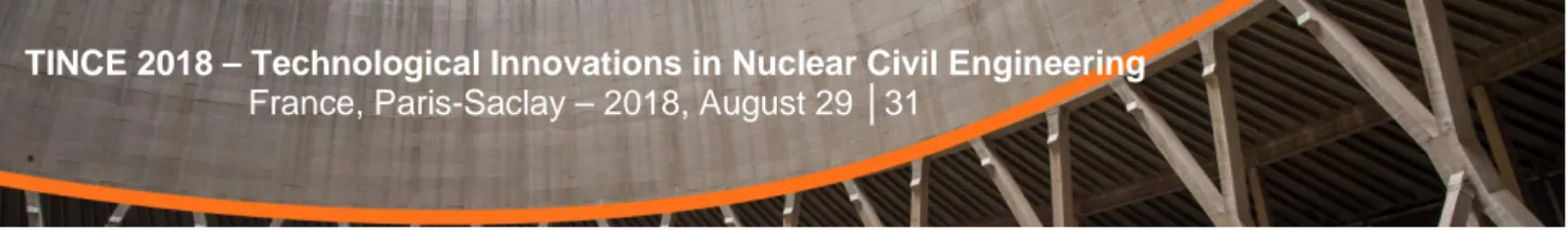
For creep experiment, they are divided in 2 groups (table 1), the first half is placed in an irradiation chamber (Fig. 3), the second one outside, close to the irradiation chamber. Temperature inside the irradiation chamber is not controlled, nevertheless samples are in the same temperature and relative humidity conditions inside and outside. At least, to be representative of the mechanical loading in the repository, 4 samples of each are compressed with a dedicated device using hydraulic jack (Fig. 5). Two samples are gathered superimposed on the same frame. The two lasts samples are free to monitor the creep without mechanical loading. The mechanical constraint is generated with a common hydraulic circuit to be sure to apply the same pressure on all samples. Mechanical load on sample is about 22 MPa which represents more or less 30 % of the compression resistance. This stress is reached with our devices with a hydraulic pressure of 310 bar.
For redundancy, each cylindrical sample is equipped with 5 strain or displacement sensors coming from two different technologies (gauges and LVDT). These sensors are distributed around the sample (some in front of the sample in the maximal γ-flux, some behind where the γ-flux is lower) to calculate the strain averages with a good accuracy (Fig. 4). Same sensors are used on passive specific device as reference to be sure that their performances are not affected by irradiation.
Moreover, twelve prismatic samples (7 cm x 7 cm x 28 cm) have also be considered for dimensional measurements and traditional mechanical tensile test. Half of them are dedicated to total shrinkage while the others are dedicated to endogenous shrinkage protected against drying (Fig. 3 and table 1). They are not instrumented and measured before and after the experiment.
Environmental parameters, temperature, relative humidity and loading are also monitored inside and outside the irradiation chamber.
The irradiation chamber is a 5 m x 5 m room with nine 60Co sticks, centred for a total activity close to
740 TBq at the beginning of the experiment. The gamma dose rate on samples is representative of the maximal dose rate from an ILW-LL in operating conditions. To be more precise, in situ measurement of gamma dose rate is ≈34 Gy/h in the core center of the samples, ≈20 Gy/h behind and ≈54 Gy/h in front of the samples, in agreement with concrete gamma attenuation (Fig. 5). Dosimetry modeling showed a difference of ± 2 Gy/h between all samples, thanks to their position relative to the sources.
Type of samples Number of samples
Gamma-irradiated Non-irradiated
Creep with loading
(cylinder Φ: 11cm H: 22 cm) 4 4
Creep without loading
(cylinder Φ: 11cm H: 22 cm) 2 2
Total shrinkage
(prism 7 cm X 7 cm X 28 cm) 3 3
Endogenous shrinkage
(prism 7 cm X 7 cm X 28 cm) 3 3
Table 1: Samples type, number and allocation
Figure 3: Photography of experiment Figure 4: Sensor location relatively to γ flux
Results
The experiment starts with the loading of the samples, which takes place step by step over 1 hour. During mechanical loading, the responses of the 5 sensors distributed around the cylindrical sample are recorded. An example, for one sample is represented figure 6. Same sensor responses separately are a guarantee of a good loading balance on the sample. Nevertheless, that condition is difficult to obtain because it requires machined surface with a very high precision, difficult to obtain on such concrete samples. In the following the creep is calculated from the average of the 5 sensors distributed around the samples.
The average strain value (measured for the 8 loaded samples) at the end of the loading stage are in very good agreement at 637 µm/m with standard deviation of 10 µm/m. All slopes are represented on figure 7, gathering 40 measurements.
Figure 6: Example of loading (strain versus stress) curves for one sample for the 5 sensors
Figure 7: Comparison of the average strain versus stress curves for the 8 samples
The creep experiment (both with loading and non-loading) lasted for 237 days representative of a total gamma dose calculated in the middle of the samples at about 180 kGy.
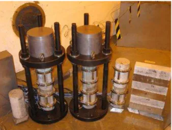
During all the experiment temperature, relative humidity and pressure in the hydraulic circuit were rec-orded. We can show on figure 8 that temperature inside the irradiation chamber and outside change daily and seasonally between 13°C and 27°C. Temperature inside the chamber is in average 1°C higher than outside. The thermal inertia of the thick concrete walls of chamber reduces the amplitude of some quick thermal changes (daily variations) especially when the external door of the building is open. There is no significant changes in the relative humidity (Fig. 9). The measured difference around 2% is in the range of the sensor accuracy. At last, the pressures in for hydraulic circuit both on the inside and outside circuits are shown on figure 10.
Of course, both temperature and pressure changes during the experiment have an influence on the creep measurement. We discuss in the following the impact of these two parameters.
Firstly it is important to note that all the mechanical components of the experiment (steel loading bench, tubes for hydraulic circuit, hydraulic jack…) are sensitive to temperature variations. Because the mod-elling of the whole thermal impact on the mechanical / hydraulic device is impossible, we have preferred to determine experimentally the thermal sensitivity of each sensor and take it into account to determine the effective creep. The curves representative to the average creeps compensated of thermal daily and seasonally changes are shown on figure 10.
To be precise:
• the average creep with loading is based on the measurements of 4 samples (each equipped with 5 sensors).
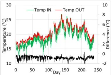
Discontinuity at the day 86, on creep with loading curves, is due to a manually pressure adjustment in the hydraulic circuit needed to maintain the global load at 22 MPa, as it can be seen on figure 10. Secondly, to avoid the impact of pressure variations in the circuit, we have represented the classical compliance parameter (creeps to stress ratio) on figure 12.
Average strain for non-loaded and γ-irradiated samples reaches -294 µm/m in comparison with - 270 µm/m for non-loaded and non-irradiated samples. At the same time, average strain on loaded and γ -irradiated samples reaches -806 µm/m in comparison with -784 µm/m on loaded and non--irradiated samples. These very low differences respectively 22 µm and 24 µm are always in favour of non-irradi-ated samples, nevertheless they are a little bit higher than the dispersion of the measurements and have to be considered as significant.
These experimental results are consolidated by a good agreement of the reference sensors under irra-diation in comparison with the same outside. Moreover, detailed results analyse shows that the meas-ured strain is independent of the sensor distribution around the sample versus the γ-flux.
Figure 8: Record of temperature in and out irradiation chamber during the experiment
Figure 9: Record of relative humidity in and out irra-diation chamber during the experiment
during the experiment
Figure 11: Average creeps for loaded and unloaded samples located under and outside the irradiation
chamber (error bars in lighter colors represent ±2σ)
Figure 12: Average compliances for loaded samples located under and outside the irradiation chamber
(error bars in lighter colors represent ±2σ)
Some classical dimensional parameters as shrinkage measurement, mass loss; and some mechanical parameters as Young modulus and compressive strength have been experimentally determined on the different kinds of samples at the end of the irradiation. These results are summarized in table 2.
Average creep with loading
— Outside irradiation chamber
— Inside irradiation chamber Average creep without loading
— Outside irradiation chamber
— Inside irradiation chamber
— Outside irradiation chamber
Parameter measured Comparison between γ-irradiated and non-irradiated
non-irradiated γ-irradiated
Creep without loading
(cylinder Φ: 11cm H: 22 cm) -270 µm/m < -294 µm/m Creep with loading
(cylinder Φ: 11cm H: 22 cm) -784 µm/m < -806 µm/m Total shrinkage
(prism 7cm X 7 cm X 28 cm) -87 µm < -98 µm
Endogenous shrinkage
(prism 7cm X 7 cm X 28 cm) -7 µm < -12 µm
Mass loss on total shrinkage
(prism 7cm X 7 cm X 28 cm) -50,2 g < -53,7 g Mass loss on endogenous shrinkage
(prism 7cm X 7 cm X 28 cm) -0,5 g ≈ -0,7 g
Tensile strength on 3 point bench
(prism 7cm X 7 cm X 28 cm) 9,3 MPa ≈ 8.9 MPa
Young’s modulus
(cylinder Φ: 11cm H: 22 cm) 36,8 GPa ≈ 36,5 GPa Compressive strength on loaded samples
(cylinder Φ: 11cm H: 22 cm) 98,7 MPa < 96,2 MPa Compressive strength on non-loaded samples
(cylinder Φ: 11cm H: 22 cm) 100,1 MPa = 100,1 MPa
Table 2: Average results for mechanical and dimensional parameters after the irradiation
Discussion
Within the experimental conditions (T, RH, dose rate) gamma irradiation has not impact on the mechan-ical properties of the tested concrete (compressive strength, tensile strength, Young’s Modulus). The differences are less than the uncertainties of the measurements.
The total shrinkage presents a difference close to 10% under or out of irradiation. The difference could be attributed firstly to a temperature inside the irradiator of 1°C more and secondly to water consumption due to radiolysis. Endogenous and total shrinkage are in accordance to the mass loss and thus a drying shrinkage can explain the radiolysis impact measured during this experiment.
Creep for irradiated and non-irradiated samples (with or without a mechanical load) are in the same order of magnitude. The differences are in accordance to the mass loss discrepancies and without any significant impact of the γ-irradiation.
Considering the conditions and the T and RH discrepancies between the irradiation chamber and the external environment, considering the dose rates used in this experiment, both samples under irradiation or not, present the same mechanical behavior. The differences measured are associated to a drying process not exactly the same in and out of the irradiation chamber.
Conclusion
Creep with loading (22 MPa, representing 30% of the compressive stress) and creep without loading has been studied on samples manufactured with representative concrete of ILW-LL containers. A ded-icated instrumented experiment has been designed and carried out in a γ-irradiator. This parameter has been complete with usual dimension and mechanical characterizations. Half of the samples were irra-diated during 8 months to an average dose-rate of 34 Gy/h up to the γ-dose 180 kGy. The conclusion is that in such irradiation conditions, our experiments show no significant effect on the mechanical prop-erties of the concrete planned to be used for ILW-LL containers.
References
1) “Geological Disposal Overview of international siting processes 2017”, Nuclear Decommissioning Authority (UK), ref: NDA Report no. NDA/RWM/157, November 2017
2) “Dossier 2005 Argile-architecture and management of a geological disposal system, Tome Architecture and management of a geological repository” ref C.RP.ADP.04.000
3) Dossier d’options de sûreté partie exploitation (DOS-EXPL), technical report Ref CG-TE-D-NTE-AMOA-SR1-0000-15-0060/A, April 2016
4) B. Craeye, G. De Schutter, H. Van Humbeeck and A. Van Cotthem, “ Early age behaviour of concrete super-containers for radioactive waste disposal”, Nuclear Engineering and Design, 239, 23-25 (2009)
5) B. Craeye, G. De Schutter, C. Vuye and Gerardy, “ Cement-waste interactions : Hardening self-compacting mortar exposed to gamma radiation”, Progress in Nulear Energy, 83, 212-219 (2015)