HAL Id: hal-01970790
https://hal.inria.fr/hal-01970790
Submitted on 7 Jan 2019
HAL is a multi-disciplinary open access
archive for the deposit and dissemination of
sci-entific research documents, whether they are
pub-lished or not. The documents may come from
teaching and research institutions in France or
abroad, or from public or private research centers.
L’archive ouverte pluridisciplinaire HAL, est
destinée au dépôt et à la diffusion de documents
scientifiques de niveau recherche, publiés ou non,
émanant des établissements d’enseignement et de
recherche français ou étrangers, des laboratoires
publics ou privés.
Selective Padding for Polycube-Based Hexahedral
Meshing
Gianmarco Cherchi, Pierre Alliez, Riccardo Scateni, Max Lyon, David
Bommes
To cite this version:
Gianmarco Cherchi, Pierre Alliez, Riccardo Scateni, Max Lyon, David Bommes. Selective Padding for
Polycube-Based Hexahedral Meshing. Computer Graphics Forum, Wiley, 2019, �10.1111/cgf.13593�.
�hal-01970790�
Selective Padding for Polycube-based Hexahedral Meshing
G. Cherchi1, P. Alliez2, R. Scateni1, M. Lyon3and D. Bommes4
1University of Cagliari, Italy.
2Inria Sophia Antipolis - Mediterranée and Université Côte d’Azur, France. 3RWTH Aachen University, Germany.
4University of Bern, Switzerland.
Figure 1: Overview. Our pipeline takes as input a model and its polycube mapping (a); we compute the relative hex-mesh and locate the surface areas in need of padding analyzing the mapping quality (b); we set and solve a binary problem to find a set of facets to extrude in order to create a selective padding layer (c); we compute and analyze the mapping with the new hex-mesh structure (d).
Abstract
Hexahedral meshes generated from polycube mapping often exhibit a low number of singularities but also poor quality elements located near the surface. It is thus necessary to improve the overall mesh quality, in terms of the minimum Scaled Jacobian (MSJ) or average Scaled Jacobian (ASJ). Improving the quality may be obtained via global padding (or pillowing), which pushes the singularities inside by adding an extra layer of hexahedra on the entire domain boundary. Such a global padding operation suffers from a large increase of complexity, with unnecessary hexahedra added. In addition, the quality of elements near the boundary may decrease. We propose a novel optimization method which inserts sheets of hexahedra so as to perform selective padding, where it is most needed for improving the mesh quality. A sheet can pad part of the domain boundary, traverse the domain and form singularities. Our global formulation, based on solving a binary problem, enables us to control the balance between quality improvement, increase of complexity and number of singularities. We show in a series of experiments that our approach increases the MSJ value and preserves (or even improves) the ASJ, while adding fewer hexahedra than global padding. Categories and Subject Descriptors(according to ACM CCS): I.3.5 [Computer Graphics]: Computational Geometry and Object Modeling—Curve, surface, solid, and object representations
1. Introduction
Volumetric meshes are an ideal tool for physically-based simulations, especially in the fields of mechanical simulation and computational fluid dynamics. While tetrahedral meshes are very simple to obtain and flexible in adapting to the computational domain, hexahedral meshes have better numerical properties and lower complexity. One straightforward way to generate a hexahedral mesh on a given do-main passes through polycube mapping.
Polycubes are three-dimensional domains formed by connecting axis-aligned cuboids face to face. The simplicity of their structure
ex-plains their popularity for several computer graphics problems such as quadrilateral and hexahedral meshing (e.g., [HXH10,GSZ11]), efficient texture mapping (e.g., [THCM04,CL⇤10]), morphing (e.g.,
[FJFS05]), spline fitting (e.g., [WHL⇤07]), etc.
When the volumetric domains to partition in hexahedra are regular enough (e.g., with limited range of levels of details like mechani-cal and CAD models), polycubes are an ideal tool for generating hexahedral meshes, by computing volumetric mappings with their corresponding domains. However, the quality of the hexahedra di-rectly depends on the mapping distortion. While the distortion is
typically negligible inside the domain (because of the regularity of the lattice we use to grid the polycube), it can be excessive near the boundary. For instance, when a convex boundary edge of the polycube with a folding angle of 90 degrees, maps to a flat part of the domain boundary, with 180 degrees.
A common solution consists in “padding” the entire domain by adding extra layers of hexahedra, in a way that pushes inside all 90-degree edges and replaces them with edges incident to two hexahedra. Padding offers a means to trade deformation for number of elements, and increases the overall quality of the domain.
In this paper, we present an automated method able to insert padding elements only where they are needed to increase the overall quality. Our algorithm works selectively on the volumetric domain, keeping untouched the parts that are directly derived from the poly-cube mapping having already a good quality. It reaches this goal op-erating selective insertion of sheets of hexahedra inside the domain. We review next the previous work relating to padding strategies, and we position our solution in terms of complexity and quality of the final hexahedral mesh.
2. State of the Art
Polycubes and Parameterization-based hex-meshing. Intro-duced in 2004 [THCM04], polycubes attracted a great attention from the Computer Graphics community, for several applications. An important field in which polycubes have immediately spread is the one of volumetric applications and hexahedral meshing, in particular for domains with limited range of levels of details [LVS⇤13,HJS⇤14,YZWL14,GSZ11,FXBH16]. Shortly after their
formalization, it was clear that the use of polycubes for purposes different from texture mapping needed an algorithmic strategy for their generation [LJFW08,HWFQ09,GSZ11]. Recent approaches improve the polycube quality by reducing the mapping distortion, lowering the number of corner singularities [LVS⇤13,HJS⇤14] and
preserving axis-rotation invariants [FBL16]. However, most of these approaches do not address the quality of polycube-generated hex-meshes.
A wide range of approaches aim at generating well-structured vol-umes, based on skeletons (e.g., [LMPS16]), gridding (e.g., [LJLJ15]) or expanding methods (e.g., [TBM96]). Parameterization-based methods are another important class of hex-meshing methods. They map the input volume to another parametric space where the final mesh connectivity is generated. With the polycubes spread, new approaches were proposed for meshing [GSZ11,LVS⇤13] and
opti-mization [CLS16,GDC15]. The added value of these approaches is clear: reasoning with a simple structure (together with a mapping function with the original shape) yields several advantages in terms of efficiency and simplicity of implementation, as a polycube can be trivially hex-meshed with a regular grid. Nevertheless, most algo-rithms devised for polycube generation overlook the quality of the elements of the final mesh.
The structure of the final mesh is defined by the shape of the polycube and the lattice in which it has been gridded (the corners of the polycube become singularities in the mesh). Such a structure is regular with high quality elements inside the domain, but it may exhibit very low quality elements near the domain boundary. For this
reason, polycube-based hex-meshes often require a post-processing step referred to as padding (or pillowing [MT95]) on the entire do-main boundary. As detailed by Shepherd [She07,SJ08], the padding operation starts with an initial mesh from which a subset of hexa-hedra is defined to create a shrink set. The shrink set is separated from the original mesh and shrunk. The void left by such a shrinking process is filled by adding a new layer of hexahedra.
The motivation for our approach stems from the observation that, for specific shapes, the padding operation is not necessary for the whole boundary. In addition, it may in some cases worsen the mesh quality. We explore the possibility to perform such a padding operation via local sheet insertion.
Hex-mesh refinement A wide range of local refinement algorithms have been proposed both for quadrilateral and hexahedral meshes [SDW⇤10]. A common objective is to change the mesh resolution,
to decrease the valence of inner vertices or to adapt the mesh density in specific areas as required by FEM simulations.
Zhu et al. [ZCWG14] proposed a method to improve the quality of CAD-based hex-meshes. While the user deforms the CAD model, the associated hex-mesh is automatically improved by adding or removing hexahedral sheets by using dual operations, in order to keep the resolution and the quality of the mesh constant. In our setting the regularity of the mesh is guaranteed by the polycube properties. We can hence limit our topology changes to the mesh boundary.
Chen et al. [CGWW16] introduced an approach to achieve com-plex sheet inflation under various constraints, in order to improve the mesh quality. The method takes as input a set of user-defined boundary mesh edges and a set of hexahedra. The edges specify the boundary position where the new sheets should be inserted, and then the algorithm computes, through an iterative solving of a Max-Flow and optimization steps, the whole layer position. In our meshes, even if we allow the sheet insertion in all the mesh, we restrict the quality analysis to the mesh surface, because polycube-based hex-meshes always have regular and good-quality inner elements. For this reason, it is easier, in our case, to automatically detect the position where the insertion of a new hexahedral sheet can improve the mesh structure.
Wang et al. [WSC⇤17] proposed an automated block
decompo-sition method based on sheet operations, which generates a block decomposition from which a high-quality hex-mesh stems. They start from a B-rep solid model, compute the relative tet-mesh and finally extract a hex-mesh. They insert and collapse whole sheets of hexahedra to improve the obtained hex-mesh by solving an integral linear problem. We instead rely on the good polycube-based inner structure and insert sheets of hexahedra to improve the quality of the near-surface elements in the final hex-mesh. It is interesting enough that they agree on the importance to develop an algorithm for a robust insertion of boundary hexahedral layers, which is what we propose in this paper.
Owen et al. [OSE17] contributed a template-based approach for generating locally refined all-hex meshes. Using a restitched set of split configurations, a local refinement of the hex-mesh structure is performed, yielding elements with minimum Scaled Jacobian of 0.3. Our approach hinges upon a similar set of templates. Since we
apply the sheet insertions in polycube based hex-meshes, we can afford to use a restricted set of dual operators to achieve the desired result. Indeed, since we only have edges belonging to 1 to 4 facets in polycube-based hex-meshes, we can obtain our goal just by using the set of operators that increase by one the valence of the hex-mesh edges, where it is needed.
Wang et al. [WGZC18] presented a method to improve the topol-ogy of hex-meshes via frame field optimization and sheet operations. Starting from a hex-mesh in which they build an initial frame field, they optimize the field in order to obtain a high-quality one, that can be used to identify the most problematic areas in the mesh. Then, they adjust the structure of the mesh via a set of sheet operations. Even if we work with different topologies and perform other types of analysis, Section6compares our approach with this work as we are adopting different methods to achieve similar goals. Indeed, working with polycube-based hex-meshes, we can afford to focus our analysis on the mesh boundary, while they need to analyze the whole structure to perform the optimization.
2.1. Positioning and Contributions
In this work we present an algorithm to perform selective and lo-calized padding into polycube-based hex-meshes. The introduction of distortion when mapping an object with curved surfaces or non-right angles into an axis-aligned shape like a polycube (e.g., a sphere mapped to a cube) is inevitable. We, thus, aim here to improve the quality of the mapping by adding hexahedral elements only in se-lected and limited areas of the hex-mesh topology.
State-of-the-art padding operation - global padding in the whole hex-mesh surface - can sometimes have the opposite effect of locally worsening the quality of the mesh instead of improving it. Our idea is to analyze the quality of the mapping between the polycube space and the object space, and then to identify where a selective insertion of sheets of hexahedra can improve the quality of the final mesh. We change the topology of the mesh only where it is needed, and we leave it untouched in areas where the quality is already acceptable. 3. Rationale and Overview
The starting point of our approach is the mapping quality of the hexahedral mesh elements. We choose as error metric the Scaled Jacobian (SJ) which computes, for each hexahedron, a value be-tween 1 and 1. When SJ = 1 the hexahedron is a perfect cube with highest possible quality. When SJ 0 the hexahedron is flipped and thus unfit to further processing. The quality of a hexahedron is judged low when SJ is smaller than a user-specified threshold.
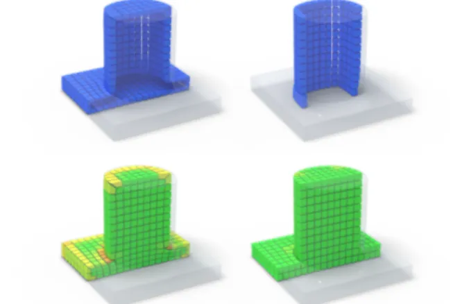
We now select a simple example to convey the intuition behind our approach. Assume a box-cylinder object formed by a right box and a cylinder on top, as depicted by Figure2. When computing the hex-mesh of such an object by gridding its polycube, the distortion is localized in the cylinder portion of the object, where the polycube forms right angles.
Performing global padding on this model decreases the quality of elements which are of high quality in the input model, as shown by second row of Figure3. By analyzing the local mapping distor-tion and performing selective padding instead, we insert a sheet of
Figure 2: Introducing distortion. From left to right: the tet-mesh of the input model, its polycube (tet-mesh) and the final hex-mesh with distortion highlighted. Here and in the other figures we use the color ramp on the right as a quality indicator where red stands for highly distorted elements, yellow for medium quality, and green stands for good quality elements.
hexahedra only around the cylinder, and straight through the box to avoid creating too many unnecessary elements and singularities (edge and vertex turns, see Figure3, top right). The additional el-ements provided by sheet insertion offer a means to improve the SJ-distortion of the low-quality elements, after vertex relocation.
Figure 3: Global vs selective padding applied to the box-cylinder model. Top: global (left) and selective (right) padding. Bottom: we show the quality of the elements induced by the two padding strategies.
It is forthwith evident the local negative effect of global padding where it is not necessary. Performing global padding increases the quality around the cylinder surface but also decreases the quality of the right box, while adding 850 elements. Our selective padding instead increases the quality only where it is needed (improving both the minimal SJ and the average SJ) and adds only 336 elements.
Figure4depicts a sub-set of three template configurations used to extrude the facets of a hexahedron element. To minimize the number of added hexahedra, we allow the new layers of hexahedra to turn, around an edge (edge turn) or a vertex (vertex turn). Note that an edge turn introduces 2 singular edges, while a vertex turn introduces 7 singular edges. For this reason, in the following sections, we pro-pose a way to balance between introduced elements and introduced singularities.
Figure 4: Padding via facet extrusion. Top to bottom: padding a single facet (one added hexahedron), padding two facets (two added hexahedra and one edge turn) and padding three facets (three added hexahedra and a vertex turn).
Overview. Our approach takes as input a volumetric mesh and its polycubes generated by the Polycut algorithm [LVS⇤13]. It
pro-ceeds in two main steps: mapping analysis (Section5) followed by selective padding (Section4). The selective padding step refines the mesh structure to provide additional elements, and hence degrees of freedom, for existing mesh optimization approaches.
More specifically, the role of the mapping analysis step is to identify a set of facets delineating hexahedra with high mapping distortion. According to an analysis of the dihedral angles between facets of bad quality hexahedra, we determine the set of facets used as padding constraints for the global solver.
Starting from these facets, our goal is to selectively pad the mesh with just-enough hexahedra to reduce distortion where needed. Our solution to preserve the structure of the hexahedral mesh is to pro-ceed by sheet insertion, the sheets being decomposed into a series of consistent facet extrusion operators.
We formulate a model with a constrained objective function with binary variables: one variable per facet; one variable per edge (to count edge turns) and one variable per vertex (to count vertex turns). The goal of the optimization is to find a satisfactory balance between quality, number of elements and number of singularities.
4. Selective Padding
We pose the local padding problem as a binary all-linear problem with a set of constraints that preserve the consistency of the topo-logical hex-mesh structure. Given a set of Hard-constrained Facets (HF) which should be padded, the solution of the binary problem yields a set of facets which allow a consistent padding that includes at least the facets from HF. Our formulation enables the user to trade the number of additionally padded facets for the number of singularities introduced via padding.
4.1. Simple Binary Problem
Let M = (V,E,F,H) be the polycube-based input hex-mesh com-posed of vertices, edges, facets and hexahedra. We create a binary variable x fifor each facet specifying whether this facet should be padded (through extrusion) or not. By definition, every inner edge of a polycube-based hex-mesh has four incident facets. If we need to change the mesh by extruding facets (as explained in Section4.3), we can extrude, for an inner edge, only two or four facets without creating topological inconsistencies. The outer edges, on the other hand, can be incident to 1, 2 or 3 hexahedra. We denote by E1H, E2H and E3H these sub-sets of edges.
Our first objective is to pad as few facets as possible: Epadding=|H|
2 3
Â
fi2F\HF
x fi (1)
where the term |H| 23 is added to achieve resolution independence.
We enforce two constraints during optimization. Firstly, all facets in HF must be padded:
x fi=1 8 fi2 HF (2)
Secondly, in order to achieve a valid, hex-topology preserving padding, we require the number of padded facets around each edge, but the ones belonging to E1H and E2H, to be even:
Â
fi2F(ej)
x fi=2kj 8ej2 E \ (E1H [ E2H) (3)
where kjis an integer variable defined for each edge involved in this constraint, and F(ej)is the set of the facets incident to edge ej. We need to treat them in different ways with respect to the constraint. 1. Edges in E1H can have 0, 1 or 2 selected incident facets. All
these configurations are suitable.
2. Edges in E2H can only have three incident facets, two on the surface and one inside. Almost all the possible paddings are legal: (i) the padding of the inner facet, (ii) the padding of both surface facets, (iii) the padding of one of the surface facets along with the inner one, causing an edge turn, and (iv) the padding of all three facets. We insert in the model a custom constraint to avoid the case of padding only one of the surface facets that would cause a topological inconsistency.
3. Edges in E3H are covered in the general constraints of Eq3. We are aware that in this way we are excluding legal cases but, considering how we define the insertion of new layers via facet extrusion, they would not generate valid solutions. We are, more-over, not limiting the possibility to reach an optimal solution. Figure5illustrates an example solution of this simple binary problem. We extend next our formulation in order to reduce the number of inserted singularities.
4.2. Binary Problem Extension
Minimizing Epaddingalone under constraints2and3yields a valid solution with the lowest number of extra elements. In practice, however, this may not always be the desired solution. As depicted by
c 2018 The Author(s) .
Figure 5: An example of our padding strategy. In (a) the red set of facets has to be extruded; in (b) the solution obtained with the basic formulation; the mesh in (c) is similar but, in this case, padding straight to the bottom would insert many hexahedra. Our simple formulation finds the solution in (d) with fewer added hexahedra by introducing edge and vertex turns inside the mesh.
Figure5d, the padding may introduce singularities inside the mesh. While adding few more hexahedra is often better than introducing extra singularities, turns of the padding layer provides us with a means to avoid generating many extra elements. A trade-off between extra elements and extra singularities is required.
We thus extend our problem formulation with a binary variable teifor every edge ei2 E, recording a turn configuration at the location of ei(cf. Figure4middle) and thus the introduction of a pair of valence 3 and 5 edges. Additionally, we add a binary variable tvlfor every vertex vl2 V , recording a vertex turn configuration (cf. Figure4bottom). Using these edge and vertex variables we can formulate the additional objective of keeping the number of introduced singularities low (e.g., minimizing the number of layer turns) via: Ecomplexity=|H| 1 3
Â
ej2E⇤\E1H tej +Â
vl2V⇤\V 1H tvl (4)where E⇤and V⇤are the sub-sets of edges and vertices that are incident to two orthogonal facets of HF since these layer’s turns are unavoidable and will be in the final solution. As for edges, V 1H denotes the sub-sets of vertices incident to only one hexahedron. As before we add the term |H| 13 to the left sum to render the
formulation independent from the hex-mesh resolution.
In order to ensure that the indicator variables teiare 1 if and only if an edge turn configuration is present, we add the following constraint:
tej=|x fi x fk| 8ej2 E⇤\ E1H,
~fi= ~fk and fi,fk2 F(ej) (5)
where F(ej)denotes the set of facets incident to edge ej. According to Equation5, to detect a possible edge turn in the edge ej we
Figure 6: Detection of an edge turn. Left: two selected facets with similar orientation. Middle: |x fi x fk| = 0 hence no edge turn is detected. Right: |x fi x fk| = 1 hence an edge turn is detected.
consider a pair of facets fi,fk2 F(ej)having the same orientation (~fi= ~fk). As can be observed in Figure6, the value of the subtraction |x fi x fk| determines whether an edge turn is present in ej.
Similarly, to ensure that the indicator variables tvlare 1 exactly when a vertex turn configuration is present we add the following constraint:
tvl=|tei tek| 8vl2 V⇤\V 1H,
~ei= ~ek and ei,ek2 E(vl) (6)
where E(vl)denotes the set of edges incident to vertex vl. According to Equation6, to find a vertex turn we consider a pair of edges ei,ek in the set of edges incident to vlin E(vl)having the same orientation (~ei= ~ek). We subtract, in absolute value, the te variables of the selected edges and can thus detect whether a vertex turn is present in vl.
Finally, under constraints2,3, 5and6, we optimize a linear combination of Epaddingand Ecomplexity:
min E = Epadding+l · Ecomplexity (7)
Adjusting the coefficientl provides the user with a means to trade the number of extra elements for the number of extra singularities. Figure12illustrates the output solution for three different values of l.
Note also that, satisfying Equation2for all surface facets is a feasible solution, so we can say that a solution satisfying the aforementioned constraints always exists.
4.3. Sheet Insertion
The output of the solver is a set of facets PF representing the ar-eas where one or several hexahedral sheets must be inserted. We generate the padding layer by extruding each facet fi2 PF and transforming it into a hexahedron. The set of extruded facets forms the new layer. We extrude each facet in both directions, considering a fraction of the edge lengths of incident hexahedra as a reference, except for the surface facets which are extruded only towards the in-side. The final structure of the mesh, including the new elements, is deduced from analyzing the global configuration of facets in PF. As shown by Figure7, the extra singularities are decided in accordance to the adjacent facets.
Figure 7: Example of padding configurations and associated sheet insertions. When four facets are selected (a) the resulting new layer of hexahedra introduces new singularities, depicted with red circles (b). If the same four facets are selected, together with four more ones (c) the final layer is different (d), and there are no extra singularities added.
5. Mapping Analysis
In the previous section we described a method which, given a set of facets HF that need to be padded, finds a complete set of facets which can be extruded while preserving the hex-mesh structure. We now detail how we find a suitable set HF such that the completed padding improves the quality of the hex-mesh.
5.1. Distortion per Facet
As polycube-based hex-meshes are commonly well shaped inside the domain, our main idea is to analyze the boundary hexahedra in order to identify the ones which would benefit from being padded. The quality of a hex-mesh is commonly measured via the Scaled Jacobian (SJ). For each hexahedron in the hex-mesh we compute the minimum determinant of the Jacobian matrix, evaluated at each of its 8 corners, and the center of the element, divided by the corre-sponding edge lengths. According to the Verdict manual [SEK⇤07],
a “good” quality hex-mesh should have only hexahedra hi such
that SJ(hi) 0.5. As we observed in our experiments, improving the quality of the mesh beyond this value is sometimes possible. Therefore, we decided to limit our analysis to the boundary hexa-hedra whose Scaled Jacobian is lower than T = 0.6, considering the remaining ones as already good. This value may be, of course, adjusted to fit application-specific requirements.
The quality of a boundary hexahedron can often be improved by padding. However, padding all its facets is not suitable (cf. Figure3). We must therefore transition from a distortion measure per hexahe-dron to a distortion measure per facet, where a high facet distortion indicates that padding is required. The set HF of facets which must be padded can then be simply defined as those facets whose distor-tion measure exceeds a user-specified threshold T derived from the quality requirement of a specific application.
We do the transition in two steps. First, we define a distortion measure per boundary edge based on the dihedral angle between incident facets. The distortion of a facet is then defined as the max-imum of the distortion of the four facet edges. In Section4.1, we introduce the sub-sets of edges E1H, E2H and E3H as the edges respectively incident to 1, 2 and 3 hexahedra. Since padding the facets incident on the edges of E2H introduces two new hexahedra which again share a E2H edge, distortion is unlikely to improve. We therefore only consider boundary edges in E1H and E3H, both shown in Figure8.
Figure 8: Example of E1H edge (left) and of E3H edge (right). For each boundary singular edge, belonging to either E1H or E3H, we compute the dihedral angles between its incident boundary facets asq = !ni· !nj (see Figure8to identify niand nj), and we measure how much they deviate from their ideal values (90 for the E1H edges or 270 for the E3H ones). For E1H surface edges,
we define D(e) =q if q 0.5 and 0 otherwise. For E3H surface
edges, we computeq based on the two incident inner facets fiand fj, because they determine the angle we need to split in case of high distortion. We define D(e) = |q| if q 0.5 and 0 otherwise. We finally assign a value D( f ), between 0 and 1, to the surface facets, to record how much it is necessary to extrude them in order to improve the quality of the mesh. We define D( f ) as the maximum distortion of the four incident edges: D( f ) = maxe2 fD(e). In this step we ignore areas of the mesh composed only by hexahedra with SJ T . 5.2. Padded Facets
Each facet of the polycube hex-mesh surface is now assigned a distortion value. In our experiments, we observed that the direct use of these values to determine the set of constrained padding facets HF is not ideal as they may form a fragmented set with isolated low distortion facets in the middle of high distortion patches, and vice-versa (see Figure10). To obtain a more consistent set of uniform patches of facets HF we first smoothly propagate the distortion values, then define HF via the solution of a Max Flow - Min Cut problem.
Figure 9: Example of propagation of the D( f ) values on the domain boundary, with k = 4.
To propagate the distortion values associated with the surface facets, we apply a simple iterative flooding algorithm that starts from facets with D( f ) 6= 0 and fills the adjacent empty ones. The process is iterated for a maximum number of steps denoted by k in the following formula:
D( fi)n+1=D( fj)n· e 2n 8 fi2 Nb(fj), 0 n k (8)
c 2018 The Author(s) .
where n is the current iteration, e 2nis a term to favor a soft
prop-agation of the deformation values (see Figure9), and Nb(fi)is the set of neighboring boundary facets of fi. The described formula is applied only to facets with D( f ) = 0, while the facets with a value different from 0 are not changed.
The Max Flow - Min Cut graph is defined by two nodes for the two used labels (L1for facets f 2 HF and L0for the other facets), a node for each surface facet, an arc between adjacent surface facets and an arc between facet nodes and label nodes. We then formulate the Max Flow - Min Cut problem as follows:
E(L) =
Â
f 2SHPf(Lf
) +
Â
h fp,fqi
Ppq(Lp,Lq) (9)
where SH is the set of hexahedra with at least one face on the boundary. Pf(Lf)represents a penalty for cutting an arc between a facet fiand the label Lfi. We define Pfias:
Pfi(Li) =1 |li D( fi)| (10)
where li=0 for Pfi(L0)and li=1 for Pfi(L1). Assume D( fi)is
close to 1: Pfi(L0)' 0 and Pfi(L1)' 1. Therefore, it is convenient
to cut the arc between fiand L0and to assign to fithe label L1. Note that assigning the facet fito the label L1corresponds to inserting fi in the HF set of hard constraints.
The right sum represents the penalty for cutting an arc between two adjacent facets fpand fq. In other words, it assigns a price to assigning two labels Lpand Lqto two adjacent facets fpand fqand Lp6= Lq. We define Ppqas:
Ppq(Lp,Lq) = [1 |D( fp) D( fq)|] · [D( fp) +D( fq)] (11) where [1 |D( fp) D( fq)|] measures the difference between D( fp) and D( fq), and [D( fp) +D( fq)]favors cuts between arcs in low distortion areas.
The solution of the Max Flow - Min Cut returns a collection of facets ready to be used as hard constraints (HF) in the binary prob-lem formulation described in Section4. As shown by Figure10they are organized in consistent patches with neither holes nor isolated facets.
While the above steps may appear ad-hoc, they offer a robust way to produce homogeneous patches of hard constraints. We also considered the alternative solution to compute one distortion value per facet then use such values as soft constraints by modifying the objective function. However, considering the negligible time required by the graph-cut solve step (fractions of a second), we decided to keep this method in order to provide the solver with a set of hard constraints. By using hard constraints obtained as described above, we achieve better results (concerning both quality and singularity count) in considerably lower time. Moreover, by visual inspection of the hard constraints, users are provided with the guarantee that they will be part of the final solution.
6. Results
All our experiments are conducted on a computer equipped with an Intel Core i7 4GHz processor, 16GB of RAM and Linux OS. We
Figure 10: Computing hard constraints. Left: D( f ) values associ-ated to each facet after the first step; notice, on the top model the isolated high-distortion elements, on the bottom model the isolated low-distortion elements (pointed by the arrows). Middle: D( f ) val-ues after the propagation. Right: final constraints resulting from solving the Max Flow - Min Cut formulation, which have filled the gaps.
used the data structures of the Cinolib [Liv17] library for developing our C++ suite of code, the Max-Flow algorithm proposed in [BK04] to compute the hard constraints set, and Gurobi [GO16] as numerical solver. We used Polycut [LVS⇤13] to produce polycube-maps,
im-plemented the meshing pipeline described in [GSZ11] to produce all the polycube-based hex-meshes, and used the hex-mesh optimizer described in [LSVT15] to optimize the showed results. For a fair comparison, we apply the optimizer in the no-padded version and in the ones with global and selective padding, to show the differences in using it to the different meshes. During optimization we set the surface attraction as high as possible to preserve the original shape of the model. In this way, we always obtain, for each one of the models in this paper, a maximum Hausdorff distance lower than 0.009 w.r.t. the bounded box diagonal.
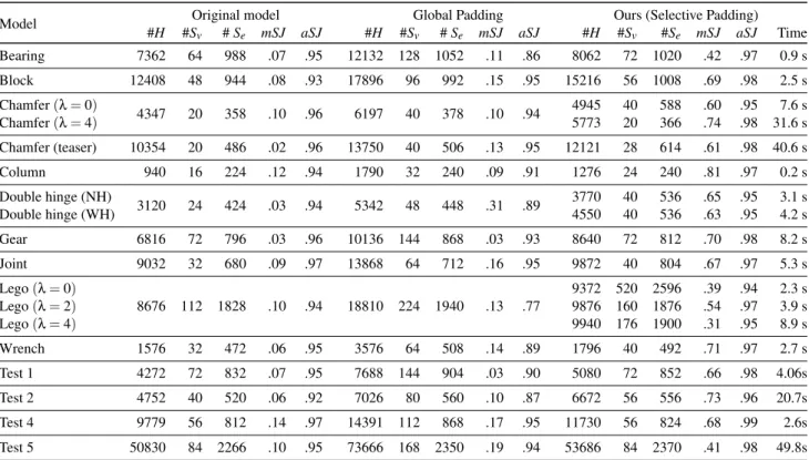
In all the figures depicting results we use the following color-code: the mesh separatrices are depicted in red, and the quality of the mesh elements ranges from green (good) to red (bad). For each model we compare the hex-mesh directly derived from the polycube with the hex-meshes with global and selective padding applied. Table1reports the most relevant data for our models: hexahedra count; quality of hexahedra in terms of minimum and average Scaled Jacobian; number of singularities (vertices and edges); time required by the solver to identify the set of facets to extrude. The sheet insertion operation takes less than a few seconds and thus we do not report it, since it is negligible.
Model #H #SOriginal model Global Padding Ours (Selective Padding)
v # Se mSJ aSJ #H #Sv # Se mSJ aSJ #H #Sv #Se mSJ aSJ Time
Bearing 7362 64 988 .07 .95 12132 128 1052 .11 .86 8062 72 1020 .42 .97 0.9 s Block 12408 48 944 .08 .93 17896 96 992 .15 .95 15216 56 1008 .69 .98 2.5 s Chamfer (l = 0) 4347 20 358 .10 .96 6197 40 378 .10 .94 4945 40 588 .60 .95 7.6 s Chamfer (l = 4) 5773 20 366 .74 .98 31.6 s Chamfer (teaser) 10354 20 486 .02 .96 13750 40 506 .13 .95 12121 28 614 .61 .98 40.6 s Column 940 16 224 .12 .94 1790 32 240 .09 .91 1276 24 240 .81 .97 0.2 s Double hinge (NH) 3120 24 424 .03 .94 5342 48 448 .31 .89 3770 40 536 .65 .95 3.1 s Double hinge (WH) 4550 40 536 .63 .95 4.2 s Gear 6816 72 796 .03 .96 10136 144 868 .03 .93 8640 72 812 .70 .98 8.2 s Joint 9032 32 680 .09 .97 13868 64 712 .16 .95 9872 40 804 .67 .97 5.3 s Lego (l = 0) 8676 112 1828 .10 .94 18810 224 1940 .13 .77 9372 520 2596 .39 .94 2.3 s Lego (l = 2) 9876 160 1876 .54 .97 3.9 s Lego (l = 4) 9940 176 1900 .31 .95 8.9 s Wrench 1576 32 472 .06 .95 3576 64 508 .14 .89 1796 40 492 .71 .97 2.7 s Test 1 4272 72 832 .07 .95 7688 144 904 .03 .90 5080 72 852 .66 .98 4.06s Test 2 4752 40 520 .06 .92 7026 80 560 .10 .87 6672 56 556 .73 .96 20.7s Test 4 9779 56 812 .14 .97 14391 112 868 .17 .95 11730 56 824 .68 .99 2.6s Test 5 50830 84 2266 .10 .95 73666 168 2350 .19 .94 53686 84 2370 .41 .98 49.8s
Table 1: Statistics. We compare three meshes: input, with global padding and with our selective padding method. For each model we report the number of hexahedra (#H), the number of singular vertices and edges (#Svand #Se), and the minimum and average Scaled Jacobian (mSJ and aSJ). For the Chamfer and Lego models we record the results obtained with differentl values, to measure the impact of l over the final mesh. For the “Double hinge” model we report the version without padding the holes (NH) and the one with padded holes (WH). It shows that padding concave angles, sometimes, does not significantly improve the final quality. We apply our algorithm on the models Test 1, 2, 4 and 5 taken from [WGZC18].
As we commented in the introduction, the padding operation usually improves the global quality of a volumetric mesh. We are able to show that our selective padding allows to obtain a substantial quality improvement over the global padding. In Table1we also show that, on the top of obtaining a better quality, our method adds fewer extra elements than global padding. The only trade-off to pay is, sometimes, the increased number of singularities.
Table2records a brief comparison between the results of our algorithm and the one described in [WGZC18], applied to the same domains. As we have not been granted access to the original soft-ware, we performed comparisons on a series of results produced by their algorithm. Therefore, starting from the same shape, we extract and optimize a polycube-based structured hex-mesh, while they analyze and optimize an unstructured one. This allows us to start from a regular structure of good quality inside the shape, and apply our algorithm just on the surface. We obtain comparable or better results for both the minimum and average Scaled Jacobian. Extra elements vs extra singularities. The improvement of the hex-mesh structure requires to find the right trade-off between the number of extra elements and the number of extra singularities. The user-specifiedl parameter controls the number of turns of the inserted sheets and therefore the addition of singular vertices to the
Model [mSJWGZC18aSJ] mSJOursaSJ
Test 1 .35 .94 .66 .98
Test 2 .34 .88 .73 .96
Test 4 .64 .96 .68 .99
Test 5 .39 .89 .41 .98
Table 2: A comparison between results obtained with our approach and those obtained with [WGZC18].
mesh structure. Figure12shows the differences in the final result for the Lego model, depending on the usedl value. With a low l value the solver can insert turns everywhere in the mesh structure, with the goal of padding as few facets as possible. With a highl value the number of turns – and new singularities – is limited at the price of adding more extra elements. Finding the well-balancedl value allows to reach a reasonable compromise between extra elements, extra singularities and final quality, as it is shown in Figure12d.
Figure 11: A gallery of results obtained with our method compared to the input mesh and global padding. GP stands for global padding and SP for selective padding (ours). In red are singular edges. Colors indicates quality as described in Figure2. In the front half of the mesh we show only the hexahedra with a Scaled Jacobian below 0.75, the others are transparent.
(a) Input mesh (b) Global Padding
(c) Ours (l = 0) (d) Ours (l = 2) (e) Ours (l = 4)
(f) Ours (l = 0) (g) Ours (l = 2) (h) Ours (l = 4)
Figure 12: Padding the “Lego” mesh. Global padding (b), and selective padding (c, d, e). The padding layers are shown in blue in (f, g, h).
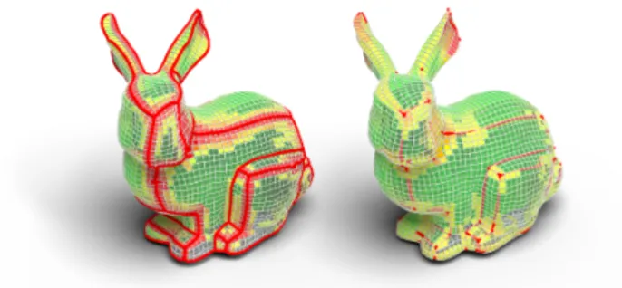
Timing. The solver’s timing depends on the number of elements in the mesh and its shape. The solution space varies depending on the input structure of the mesh. We usually use “coarse” meshes to solve the padding problem since a refinement step is always possible in post-processing (e.g., splitting each hexahedron in eight sub-hexahedra). When a model is complex enough not to allow to start from coarse hex-meshes, the solver can require up to several minutes of computation to produce the set of facets to extrude. Mechanical parts vs. organic shapes. As mentioned in Section1, polycubes are an ideal tool for generating hexahedral meshes of quite regular shapes with a limited set of details. In this class of objects, mechanical pieces and CAD models are relevant subsets. As it is clear from our results, we focus our attention on this class of objects. Indeed, the application of our selective padding on organic and free-form polycube-based shapes produces the same result of global padding. In Figure14, we show the use of our algorithm on the Bunny model. It is evident that, to improve the mesh quality, we need to push inside all the singular edges of the mesh.
6.1. Limitations
While our experiments show excellent results, improving the quality of both the original and the global padding models, we cannot prove that our approach reaches the maximum possible quality for the chosen application field. Searching for the best trade-off between complexity and distortion would require either trying all possible l values and then selecting the one yielding the best results, or
(a) Input (b) Global Padding
(c) Ours (padding holes) (d) Ours (not padding holes)
(e) Ours (padding holes) (f) Ours (not padding holes)
Figure 13: Padding the “Double hinge” mesh. Global padding (b), and selective padding, including holes (c) and without holes (d). The padding layers are shown in blue in (e , f).
proceeding by dichotomy. According to our experiments, the value of thel parameter which leads to the best results depends on the shape of the model. It is thus not possible to suggest the silver bullet value ofl that could work for any model. The choice of l can be a fine-tuning task and we let the user set it interactively.
Our method can detect distortion in the proximity of all concave tunnels in models with genus greater than 0. For simplicity, we refer to these particular shapes as “Holes”. However, padding the holes is not always relevant for improving the overall quality. Experiments carried out on the Double hinge model (Figure13) show that the quality can even decrease.
In the end, we produce a new hex-mesh topology suitable for obtaining a good quality final mesh, but the final quality is strictly dependent on the hex-mesh optimizer. We use the approach from [LSVT15] but, considering that the untangling is still an unsolved task in 3D, our results may not have the desired quality despite their good structure.
c 2018 The Author(s) (a) Input mesh (b) Global Padding
(c) Ours (l = 0) (d) Ours (l = 2) (e) Ours (l = 4)
(f) Ours (l = 0) (g) Ours (l = 2) (h) Ours (l = 4)
Figure 12: Padding the “Lego” mesh. Global padding (b), and selective padding (c, d, e). The padding layers are shown in blue in (f, g, h).
Timing. The solver’s timing depends on the number of elements in the mesh and its shape. The solution space varies depending on the input structure of the mesh. We usually use “coarse” meshes to solve the padding problem since a refinement step is always possible in post-processing (e.g., splitting each hexahedron in eight sub-hexahedra). When a model is complex enough not to allow to start from coarse hex-meshes, the solver can require up to several minutes of computation to produce the set of facets to extrude. Mechanical parts vs. organic shapes. As mentioned in Section1, polycubes are an ideal tool for generating hexahedral meshes of quite regular shapes with a limited set of details. In this class of objects, mechanical pieces and CAD models are relevant subsets. As it is clear from our results, we focus our attention on this class of objects. Indeed, the application of our selective padding on organic and free-form polycube-based shapes produces the same result of global padding. In Figure14, we show the use of our algorithm on the Bunny model. It is evident that, to improve the mesh quality, we need to push inside all the singular edges of the mesh.
6.1. Limitations
While our experiments show excellent results, improving the quality of both the original and the global padding models, we cannot prove that our approach reaches the maximum possible quality for the chosen application field. Searching for the best trade-off between complexity and distortion would require either trying all possible l values and then selecting the one yielding the best results, or
(a) Input (b) Global Padding
(c) Ours (padding holes) (d) Ours (not padding holes)
(e) Ours (padding holes) (f) Ours (not padding holes)
Figure 13: Padding the “Double hinge” mesh. Global padding (b), and selective padding, including holes (c) and without holes (d). The padding layers are shown in blue in (e , f).
proceeding by dichotomy. According to our experiments, the value of thel parameter which leads to the best results depends on the shape of the model. It is thus not possible to suggest the silver bullet value ofl that could work for any model. The choice of l can be a fine-tuning task and we let the user set it interactively.
Our method can detect distortion in the proximity of all concave tunnels in models with genus greater than 0. For simplicity, we refer to these particular shapes as “Holes”. However, padding the holes is not always relevant for improving the overall quality. Experiments carried out on the Double hinge model (Figure13) show that the quality can even decrease.
In the end, we produce a new hex-mesh topology suitable for obtaining a good quality final mesh, but the final quality is strictly dependent on the hex-mesh optimizer. We use the approach from [LSVT15] but, considering that the untangling is still an unsolved task in 3D, our results may not have the desired quality despite their good structure.
Figure 14: Selective padding in organic shapes. On the left the model without padding, on the right the selective padding (equiva-lent to the global one) applied on the same model.
7. Conclusion and Future Work
We introduced in this paper a novel pipeline for the generation of quality hexahedral meshes, where high quality of a hexahedron refers to low deviation from the perfect cube. Our pipeline utilizes a polycube mapping for decomposing the input 3D domain into portions which are simple to discretize into a hexahedral mesh. In this pipeline our main contribution is a selective padding step which automatically adds sheets of hexahedra only where they are needed, in order to increase the global quality of the output hexahedral meshes. These sheets can form turns inside the domain, which induce extra edge and vertex singularities. Compared to global padding or greedy straight sheet insertion, our approach improves the global quality while generating fewer hexahedra. It works at its best when applied to input domains bounded by a piecewise planar surface, which is typical of mechanical parts. On concave holes the gain is only moderate.
In the future we plan to explore an automatic parameter selection approach in order to find the best balance between quality and com-plexity. We also wish to explore a global optimization approach to select the optimal set of constrained facets that yields the maximum quality. We then intend to analyze whether a combination of padding and inverse padding (remove hexahedral layers from the mesh) can provide better results. Furthermore, we plan to extend our approach to more general polycube-based hex-mesh structures, like those used by Fang et al. [FXBH16].
Acknowledgments
We thank the authors of [WGZC18] for sharing with us the models used in their article. Gianmarco Cherchi gratefully acknowledges the European Erasus+ program for funding his period at INRIA. This work is partly financed by the DSURF PRIN 2015 (2015B8TRFM) project.
References
[BK04] BOYKOVY., KOLMOGOROVV.: An experimental comparison of min-cut/max- flow algorithms for energy minimization in vision. IEEE Transactions on Pattern Analysis and Machine Intelligence 26, 9 (Sept 2004), 1124–1137.doi:10.1109/TPAMI.2004.60.7
[CGWW16] CHENJ., GAOS., WANGR., WUH.: An approach to achieving optimized complex sheet inflation under constraints. Computers
& Graphics 59 (2016), 39 – 56. doi:10.1016/j.cag.2016.05. 001.2
[CL⇤10] CHANGC.-C., LINC.-Y.,ET AL.: Texture tiling on 3d models using automatic polycube-maps and wang tiles. Journal of Information Science and Engineering 26, 1 (2010), 291–305.1
[CLS16] CHERCHIG., LIVESUM., SCATENIR.: Polycube Simplifica-tion for Coarse Layouts of Surfaces and Volumes. Computer Graphics Forum 35, 5 (2016), 11–20.doi:10.1111/cgf.12959.2
[FBL16] FUX.-M., BAIC.-Y., LIUY.: Efficient Volumetric PolyCube-Map Construction. Computer Graphics Forum 35, 7 (2016), 97–106.
doi:10.1111/cgf.13007.2
[FJFS05] FAN Z., JIN X., FENG J., SUN H.: Mesh morphing us-ing polycube-based cross-parameterization. Computer Animation and Virtual Worlds 16, 3-4 (2005), 499–508. arXiv:https:// onlinelibrary.wiley.com/doi/pdf/10.1002/cav.92,
doi:10.1002/cav.92.1
[FXBH16] FANGX., XUW., BAOH., HUANGJ.: All-hex meshing using closed-form induced polycube. ACM Trans. Graph. 35 (2016), 124:1–124:9.2,11
[GDC15] GAO X., DENG Z., CHEN G.: Hexahedral Mesh Re-parameterization from Aligned Base-complex. ACM Trans. Graph. 34, 4 (July 2015), 142:1–142:10.doi:10.1145/2766941.2
[GO16] GUROBIOPTIMIZATIONI.: Gurobi Optimizer Reference Manual, 2016. URL:http://www.gurobi.com.7
[GSZ11] GREGSONJ., SHEFFERA., ZHANGE.: All-Hex Mesh Gen-eration via Volumetric PolyCube Deformation. Computer Graphics Fo-rum 30, 5 (2011), 1407–1416.doi:10.1111/j.1467-8659.2011. 02015.x.1,2,7
[HJS⇤14] HUANGJ., JIANGT., SHIZ., TONGY., BAOH., DESBRUN M.: `1-Based Construction of Polycube Maps from Complex Shapes. ACM Trans. Graph. 33, 3 (June 2014), 25:1–25:11. doi:10.1145/ 2602141.2
[HWFQ09] HEY., WANGH., FUC. W., QINH.: A divide-and-conquer approach for automatic polycube map construction. Computers and Graphics 33, 3 (2009), 369–380.doi:10.1016/j.cag.2009.03. 024.2
[HXH10] HANS., XIAJ., HEY.: Hexahedral shell mesh construction via
volumetric polycube map. In Proceedings of the 14th ACM symposium on solid and physical modeling (2010), ACM, pp. 127–136.1
[Liv17] LIVESU M.: cinolib: a generic programming header only
C++ library for processing polygonal and polyhedral meshes., 2017. https://github.com/maxicino/cinolib/.7
[LJFW08] LINJ., JINX., FANZ., WANGC. C. L.: Automatic
PolyCube-Maps. In Advances in Geometric Modeling and Processing (Berlin, Heidelberg, 2008), Chen F., Jüttler B., (Eds.), Springer Berlin Heidelberg, pp. 3–16.2
[LJLJ15] LINH., JINS., LIAOH., JIANQ.: Quality guaranteed all-hex mesh generation by a constrained volume iterative fitting algorithm. Computer-Aided Design 67-68 (2015), 107–117. doi:10.1016/j. cad.2015.05.004.2
[LMPS16] LIVESUM., MUNTONIA., PUPPOE., SCATENIR.: Skeleton-driven Adaptive Hexahedral Meshing of Tubular Shapes. Computer Graphics Forum 35, 7 (2016), 237–246.doi:10.1111/cgf.13021.
2
[LSVT15] LIVESUM., SHEFFERA., VININGN., TARINIM.: Practical Hex-mesh Optimization via Edge-cone Rectification. ACM Trans. Graph. 34, 4 (July 2015), 141:1–141:11.doi:10.1145/2766905.7,10
[LVS⇤13] LIVESUM., VININGN., SHEFFERA., GREGSONJ., SCATENI R.: PolyCut: Monotone Graph-cuts for PolyCube Base-complex Con-struction. ACM Trans. Graph. 32, 6 (Nov. 2013), 171:1–171:12.doi: 10.1145/2508363.2508388.2,4,7
[MT95] MITCHELLS. A., TAUTGEST. J.: Pillowing doublets: refining a mesh to ensure that faces share at most one edge. In 4th International Meshing Roundtable (1995), Citeseer, pp. 231–240.2
[OSE17] OWENS. J., SHIHR. M., ERNSTC. D.: A template-based approach for parallel hexahedral two-refinement. Computer-Aided Design 85 (2017), 34 – 52. 24th International Meshing Roundtable Special Issue: Advances in Mesh Generation. doi:10.1016/j.cad.2016.09. 005.2
[SDW⇤10] SHEPHERDJ. F., DEWEYM. W., WOODBURYA. C., BEN
-ZLEYS. E., STATENM. L., OWENS. J.: Adaptive mesh coarsening for quadrilateral and hexahedral meshes. Finite Elements in Analysis and Design 46, 1 (2010), 17 – 32.doi:10.1016/j.finel.2009.06. 024.2
[SEK⇤07] STIMPSONC., ERNSTC., KNUPPP., PÉBAYP., THOMPSON D.: The Verdict library reference manual. Sandia National Laboratories Technical Report 9 (2007).6
[She07] SHEPHERD J. F.: Topologic and geometric constraint-based hexahedral mesh generation, vol. 68. PhD Thesis, 2007.2
[SJ08] SHEPHERDJ. F., JOHNSONC. R.: Hexahedral mesh generation constraints. Engineering with Computers 24, 3 (Sept 2008), 195–213.
doi:10.1007/s00366-008-0091-4.2
[TBM96] TAUTGEST. J., BLACKERT., MITCHELLS. A.: The whisker weaving algorithm: A connectivity-based method for constructing all-hexahedral finite element meshes. International Journal for Numerical Methods in Engineering 39, 19 (1996), 3327–3349.2
[THCM04] TARINIM., HORMANN K., CIGNONIP., MONTANI C.: PolyCube-Maps. ACM Trans. Graph. 23, 3 (Aug. 2004), 853–860.
doi:10.1145/1015706.1015810.1,2
[WGZC18] WANGR., GAOS., ZHENGZ., CHENJ.: Hex mesh topolog-ical improvement based on frame field and sheet adjustment. Computer-Aided Design 103 (2018), 103 – 117. 25th International Meshing Roundtable Special Issue: Advances in Mesh Generation.doi:https: //doi.org/10.1016/j.cad.2017.11.007.3,8,11
[WHL⇤07] WANG H., HE Y., LI X., GU X., QINH.: Polycube Splines. In Proceedings of the 2007 ACM Symposium on Solid and Physical Modeling (New York, NY, USA, 2007), SPM ’07, ACM, pp. 241–251. URL:http://doi.acm.org/10.1145/1236246. 1236281,doi:10.1145/1236246.1236281.1
[WSC⇤17] WANGR., SHENC., CHENJ., WUH., GAOS.: Sheet operation based block decomposition of solid models for hex meshing. Computer-Aided Design 85 (2017), 123 – 137. 24th International Meshing Roundtable Special Issue: Advances in Mesh Generation. doi:10. 1016/j.cad.2016.07.016.2
[YZWL14] YUW., ZHANGK., WANS., LIX.: Optimizing polycube
domain construction for hexahedral remeshing. Computer-Aided Design 46 (2014), 58–68. 2013 SIAM Conference on Geometric and Physical Modeling.doi:10.1016/j.cad.2013.08.018.2
[ZCWG14] ZHUH., CHENJ., WU H., GAOS.: Direct Editing on Hexahedral Mesh through Dual Operations. Procedia Engineering 82 (2014), 149 – 161. 23rd International Meshing Roundtable (IMR23).
doi:10.1016/j.proeng.2014.10.380.2