Comparing the quantification of Forster resonance
energy transfer measurement accuracies based
on intensity, spectral, and lifetime imaging
The MIT Faculty has made this article openly available.
Please share
how this access benefits you. Your story matters.
Citation
Pelet, Serge, Michael J. R. Previte, and Peter T. C. So. “Comparing
the Quantification of Forster Resonance Energy Transfer
Measurement Accuracies Based on Intensity, Spectral, and Lifetime
Imaging.” Journal of Biomedical Optics 11, no. 3 (2006): 034017. ©
2006 Society of Photo-Optical Instrumentation Engineers
As Published
http://dx.doi.org/10.1117/1.2203664
Publisher
SPIE
Version
Final published version
Citable link
http://hdl.handle.net/1721.1/87648
Terms of Use
Article is made available in accordance with the publisher's
policy and may be subject to US copyright law. Please refer to the
publisher's site for terms of use.
Comparing the quantification of Förster resonance
energy transfer measurement accuracies based
on intensity, spectral, and lifetime imaging
Serge Pelet
Michael J. R. Previte
Massachusetts Institute of Technology Department of Mechanical Engineering 77 Massachusetts Avenue, NE47-220 Cambridge, Massachusetts 02139
Peter T. C. So
Massachusetts Institute of Technology
Department of Mechanical Engineering and Division of Biological Engineering
77 Massachusetts Avenue, NE47-279 Cambridge, Massachusetts 02139
Abstract. The measurement of Förster resonance energy transfer 共FRET兲 in microscopes can be realized by different imaging modali-ties. In the present work, reference FRET constructs are developed to allow the comparison of FRET microscopy measurements using inten-sity, spectral, and lifetime imaging. Complimentary DNA strands are respectively labeled with Oregon Green 488 共OG488兲 or tetrameth-ylrhodamine 共TMR兲. The OG488 dye is fixed at the 5
⬘
end of one strand, and the TMR label position is allowed to vary along the com-plimentary strand. Since OG488 and TMR are FRET pairs, the FRET efficiency can be determined theoretically from the distance separat-ing the two dyes of the double-stranded DNA molecules. Microscopic images are formed by imaging microcapillaries containing various mixtures of oligonucleotides labeled with the FRET fluorophore pair, only the donor, or only acceptor. Traditional two-channel intensity measurements are compared with spectrally resolved imaging and fluorescence lifetime imaging by calculating a FRET index. The latter proves to be the best method to quantify FRET efficiency in the image. More importantly, the intensity fraction of molecules undergoing FRET can be quantitatively measured in each pixel of the image. © 2006Society of Photo-Optical Instrumentation Engineers. 关DOI: 10.1117/1.2203664兴
Keywords: Förster resonance energy transfer; fluorescence lifetime imaging; spec-tral imaging; two-photon microscopy.
Paper 05332R received Nov. 7, 2005; revised manuscript received Feb. 22, 2006; accepted for publication Feb. 22, 2006; published online May 23, 2006.
1 Introduction
Förster resonance energy transfer 共FRET兲 is a process that takes places between two fluorophores interacting at short dis-tances, resulting in a modification of their fluorescence inten-sity. The donor fluorophore transfers its electronic excitation energy via dipole-dipole interaction to the acceptor fluoro-phore. This leads to a quenching of the donor emission and an increase in acceptor emission, also called sensitized emission. This phenomenon has been widely used in biology, such as in immunology to monitor molecular binding with immuno-fluorescence assays.1–3 In this type of experiment, a binary response is expected from the assay; the presence of a FRET signal indicates the presence of the analyte in the solution. FRET is also extensively employed in single-molecule experi-ments to measure intramolecular distances and to follow pro-tein conformational changes.4,5The relative changes in FRET efficiency can facilitate the mapping of protein folding path-ways or the mechano-chemical transduction dynamics of mo-tor proteins. However, applying FRET techniques to study protein interactions in living cells is challenging.6–9 In this case, the presence of FRET will indicate that two proteins of interest interact intracellularly. However, it is often also
desir-able to quantify precisely the fraction of labeled protein that is engaged in binding interaction and the molecular distance of these protein pairs.
These quantitative experiments have gained in popularity with the discovery of the green fluorescent protein共GFP兲 and the generation of a whole set of similar fluorescent proteins 共FPs兲, whose emission spectra cover the entire visible spectrum.10–13In a typical experiment to probe protein-protein interaction, a cell is modified to express two proteins of inter-est linked by a small peptide chain to a specific variant of the FP共Cyan FP and Yellow FP or GFP and dsRed are the most common FRET pairs兲.14–17Physical and biological processes, such as protein interaction, that bring the two FPs into close proximity, will result in energy transfer. The measurement of the fluorescence of these two proteins in each pixel of the image allows the amount of FRET occurring in each location of the cell to be quantified.
Jares-Erijman and Jovin6 have presented an overview of the methods suggested and implemented to measure FRET in
vivo. The most common ones are based on intensity
measure-ments, but they are hampered with experimental artifacts due to cross-excitation and detection of the two fluorescent mol-ecules. Many correction algorithms have been published and recover the FRET efficiency with good success, but they
re-1083-3668/2006/11共3兲/034017/11/$22.00 © 2006 SPIE Address all correspondence to Serge Pelet, ETHZ Hönggerberg, Institute for
quire multiple sets of images with varying excitation and de-tection conditions, as well as with reference samples that con-tain only one of the fluorophore.18–22Acceptor photobleaching is an alternative method that avoids these complex correction schemes. With this process, the acceptor is photobleached and the donor intensity is compared before and after the pho-tobleaching step to recover the FRET efficiency.7,23However, this technique is destructive and prevents repeated measure-ments on the same cell. Finally, fluorescence lifetime imaging is becoming more commonly used to quantify FRET. The quenching of the donor dye by the energy transfer process leads to a faster decay of the excited state that can be charac-terized in a microscope with picosecond temporal resolution.14,24–27The simple quantification of the reduction of the mean lifetime of the donor decay provides a relative mea-surement of the amount of FRET in the sample. With a careful analysis of the lifetime data with a biexponential model, all FRET parameters can be recovered completely 共i.e., effi-ciency of the energy transfer, interaction distance between the two dyes, and ratio of donor involved in an energy transfer complex兲. This information is not available with any other intensity-based FRET measurements.
Using two-photon microscopy, we have studied the ability of intensity, spectral, and lifetime imaging modalities to re-cover FRET with well-characterized samples. This FRET con-struct was built based on dye-labeled DNA strands. By an-nealing complementary strands, we created a reference specimen with well-controlled energy transfer efficiency from the donor to the acceptor based on the fluorophore distance and spectral overlap. While FRET recovery using intensity, spectral, and lifetime imaging modalities has been studied previously, there is no quantitative comparison of the accu-racy and precision of the three detection modalities in FRET recovery using the same reference specimen under an identi-cal optiidenti-cal microscope, acquiring equivalent number of pho-tons.
2 Theory
Energy transfer occurs when a fluorophore is promoted to its excited state in the presence of a second nearby fluorophore. The coupling of the transition dipole of these fluorophores results in the de-excitation of the donor and excitation of the acceptor. Due to the nature of this interaction, Förster pre-dicted a dependence of the FRET efficiency on the sixth power of distance. Stryer and Haugland demonstrated this ex-perimentally with linear polypeptides of varying lengths.28 The efficiency E of the process varies as function of the dis-tance R between the two molecules as:
E = R0 6
R06+ R6, 共1兲
where R0is called the Förster distance and corresponds to the
separation were 50% of the donor fluorescence is converted into the energy transfer process. This parameter depends on the index of refraction of the medium n, the quantum yield of the donor molecule QD, the orientation factor, and the
over-lap integral J. R06=9000 ln共10兲 2Q D 1285NAn4 J. 共2兲
represents the relative orientation of the transition dipole of the donor and acceptor molecules. In most cases, a random interaction is assumed, and this factor is set to2 / 3. The over-lap integral J represents the energy overover-lap between the emis-sion of the donor and the absorption of the acceptor. For well-matched fluorophore pairs, R0 is on the order of
50 to 60 Å.29,30The efficiency of the energy transfer process 共E兲 can be linked to physically measurable parameters, such as the fluorescence intensity of the donor I or its fluorescence lifetime. E = 1 −IF ID = 1 −F D , 共3兲
where the subscript D represents a sample with only the donor present, and the subscript F is a FRET sample, where both donor and acceptor are present.
To measure FRET in a living cell under a microscope based on steady-state intensity measurements, a series of im-ages are recorded: a FRET sample and reference samples con-taining only the donor or the acceptor fluorophore under vari-ous imaging conditions. A three character symbol will be used to refer to each type of image: 12X. X refers to the sample
studied: F for sample with FRET, A for a sample with only acceptor fluorophores, and D for a sample with donor alone. The subscript 1 refers to how the sample is excited共either a for excitation in the acceptor spectrum or d for excitation in the donor excitation spectrum兲. The superscript 2 refers to the emission light that is detected共a for detecting in the acceptor emission spectrum, d for detecting in the donor emission spectrum, or s for spectrally resolved detection兲. Furthermore, for the purpose of the correction algorithm, it is necessary to differentiate the contributions of the donor or acceptor to an image. Therefore, the three character symbol representing the image can be complemented by a lower letter a or d to refer only to the contribution of the acceptor or donor to the signal. A bar over the symbol indicates the theoretical signal ex-pected if no FRET was present in the sample. As an example,
d a
Fd refers to an image of a FRET sample excited at the donor
wavelength, detected in the acceptor channel, and considering only the contribution of the donor in the case where no FRET was present.
2.1 Two-Channel Measurements
FRET is characterized by a decrease in donor intensity and an increase in acceptor intensity. For cellular systems, a single image 共ddF兲 measurement of the donor emission does not
al-low an accurate quantification of FRET, because it is not pos-sible to separate intensity changes due to intracellular concen-tration variation change or an energy transfer processes. Thus, two images of the donor 共d
d
F兲 and acceptor 共d a
F兲 emission
need to be recorded to establish that the ratio of acceptor-over-donor emission has increased. Many artifacts influence this ratio. Most importantly, the direct excitation of the accep-tor at the donor wavelength can lead to an increase in the acceptor channel unrelated to any FRET process. Thus, a third image共aaF兲 is recorded under excitation at the acceptor
wave-length to quantify the acceptor concentration, and to correct for its contribution. The recovery of the FRET index can be further improved by calibration of the spectral bleed-through and cross-excitation of both fluorophores. Calibration is per-formed by measuring these three aforementioned images us-ing reference samples that contain either the donor or the acceptor. A total of nine images are thus required to calculate the fully corrected FRET image: three images from the sample itself and six 共three from each兲 from the donor and acceptors alone.
Many algorithms have been developed to retrieve the amount of FRET present in the sample. Berney and Danuser published a comparison of the most common methods, and concluded that the algorithm published by Gordon et al. pro-vides the best recovery of the FRET parameters hidden in the image.18,19This algorithm compensates for the common arti-facts found in FRET experiments such as spectral bleed-through and cross-excitation. It allows the FRET1 index to be calculated, which is the loss of donor signal due to FRET:
FRET1 = d a F −ddFd a D d dD−a a Fa
冉
d a A a aA− d a D d dD d d A a aA冊
G冉
1 −d dA d aA d aD d dD冊
, where a aFa = a aF − d aFa aD d aD 1 −d a A a aA a a D d a D , and G =QYa QYd a d TF TD . 共4兲G is a dimensionless factor that scales the acceptor signal
intensity to the donor intensity. QY is the quantum yields of the dye,is the fraction of fluorescence transmitted through the filter set and measured by the detector, and T represents the fractional transmission of neutral density filters.
FRET1 is related to the theoretical FRET efficiency, but it still depends on the donor emission intensity. To correct for that, a FRET2 index, which is the ratio of FRET1 over the total amount of donor emission if no FRET was present 共d
d
Fd兲, is introduced and varies theoretically between 0 and 1.
FRET2 =FRET1 d d Fd , where d d Fd =ddF + FRET1
冉
1 − Gd d A a aA冊
−a a Fad d A a aA. 共5兲To obtain these corrected images 共FRET1 and FRET2兲, three images of three samples 共FRET, donor, and acceptor samples兲 must be collected with two detection channels and two different excitation wavelengths. The reference sample
images are always present in the algorithm as a ratio between two reference images, thus the average of this value for the entire image can be used in the algorithm to minimize the error.
2.2 Spectral Imaging
The whole emission spectrum of the sample in each pixel of the image can be measured with spectrally resolved microscopy.31–33At each pixel, the spectral information can be represented as a 1-D vector dsF共i兲, where i is an index of the
spectral channel. This supplementary information can be used in two different ways. The simplest method is to divide the full spectral range into two parts, whose sums provide the donor and acceptor images.
d d F =
兺
i=j k d s F共i兲 anddaF =兺
i=m n d s F共i兲, 共6兲where j, k, m, and n are the limits for the integration of the spectrum. The images calculated can be fed into the Gordon algorithm to calculate the FRET index. This technique pro-vides the advantage of selecting the most suitable spectral window for both emitters after the acquisition has been done. The second method calculates for each pixel of the image the contribution of the donor and acceptor species based on their known spectra 共spD and spA, represented by a single row vector兲 obtained from the reference samples. The spectral in-formation at each pixel is a linear superposition of the spec-trum of the donor and the acceptor.
d sF共i兲 = d dF · spD共i兲 + d aF · spA共i兲. 共7兲 The images d d F and d a
F are obtained by a least-square
op-timization. This spectral decomposition method has the ad-vantage of removing all the emission bleed-through, and it results in a simplified version of the Gordon’s algorithm.
FRET1 = d a F −aaFd a A a aA G
冉
1 −d aA a aA a dD d dD冊
, and FRET2 = FRET1 d dF + FRET1. 共8兲The terms that correct for the emission bleed-through, such as
d a
D /d d
D, equal zero and only the cross-excitation ratios remain
in the algorithm. Note that a new term adD /d d D is present to replace thea a D /d a
D ratio that accounts for the excitation of the
donor under acceptor illumination. The spectrally resolved measurements require the recording of an image set consisting of typically 16 frames with roughly10-nm bandwidth. This type of image set can be obtained in a single acquisition with a laser scanning microscope and a spectrally resolved detec-tion, or using a filter wheel and a charge-coupled device 共CCD兲 detector in wide-field imaging systems. In both cases, two different excitation wavelengths for each of the three samples 共a total of six image sets兲 are required to obtain
FRET2. Practically, FRET measurements in a spectral imag-ing microscope can be implemented as easily as traditional two-channel detection. For apparatuses that require indepen-dent recording of the various spectral components, image set collection times will increase.
2.3 Lifetime Imaging
The quenching of the donor fluorescence by the energy trans-fer process leads to an acceleration of the dynamics of the donor excited state, i.e., a shortening of its lifetime. The chro-mophore engaged in a FRET complex will have a character-istic lifetimeF fixed by the geometry of the protein-protein
interaction. In the case where both free and bound proteins are present in the sample, the fluorescence lifetime will be a double exponential decay with the time constants of the free and fretting dye. The contribution of each population to the lifetime relaxation is proportional to their respective concen-tration in the sample.
The analysis of a fluorescence lifetime imaging micros-copy 共FLIM兲 is best realized with a global fitting algorithm.34,35Equation共9兲 is a two-exponential global fitting model that assumes the existence of two fluorophore popula-tions with two lifetimesFandD关corresponding to the
co-efficients c1 and c2 in Eq. 共9兲兴, which are optimized for the
whole image. The initial intensity c2i+1and the intensity ratio
of the two lifetime components c2i+2 at each pixel i vary spatially. Note that c2i+2is bound between 0 and 1 to prevent negative contributions from the two exponentials. IR is the instrument response of the system, which is convolved with the expected fluorescence decay to obtain the measured inten-sity decay.
Iimodel共t兲 =
冕
0t
IR共t − T兲 · c2i+1
冋
c2i+2exp冉
− T c1冊
+共1 − c2i+2兲exp冉
− T c2冊
册
dT. 共9兲The lifetime analysis of the FRET sample provides the exact ratio of interacting protein in each location of the sample. Furthermore, using Eqs.共1兲 and 共3兲, it is possible to calculate the efficiency of the FRET process and obtain an approximate measurement of the distance separating the donor from the acceptor. A similar quantification cannot be realized with intensity-based measurements.
To compare these measurements with the intensity and spectral results, it is possible to convert the results from the global fitting algorithm to extract a FRET2 index. Assuming that only the donor emission is detected through the donor filter, FRET2 can be simply expressed as:
FRET2 = d d Fd −d d F d d Fd , where d dF =
兺
t Idata共t兲, d d Fd =兺
t冋
冕
0 t G共t − T兲 · c2i+1exp冉
− T D冊
册
. 共10兲An intensity image corresponding toddF can be created from
the sum over all time channels in the FLIM image. The image of the donor without the presence of FRET is easily calculated by setting the coefficient c2i+2 to zero, which represents a
decay without contribution from the FRET species.
The practical advantage of the lifetime imaging technique is that only a single image from the FRET sample at the donor excitation and emission wavelengths is needed to extract the energy transfer parameters. In practice, a donor-only sample is also measured during the same experiment as a negative con-trol.
3 Methods
The microscope setups for lifetime34and spectral imaging36 have been previously published. Briefly, the two-photon mi-croscope is based on a modified inverted mimi-croscope 共Axio-vert 110, Zeiss, Göttingen, Germany兲 using a femtosecond laser共Mira, Coherent, Santa Clara, California兲 as light source working in epi-fluorescence mode. For the two-channel image acquisition mode, the fluorescence is sent to the top port of the microscope, where it is split in a green and red detection channel using a dichroic mirror 共Q565LP兲 and appropriate filters共green: HQ500LP and E530SP, Red: HQ610/75兲 from Chroma 共Rockingham, Vermont兲 and detected by single-photon counting photomultiplier tubes 共PMTs兲 共R7400P, Hamamatsu, Bridgewater, New Jersey兲. In lifetime imaging mode, the same optical path is used, and the signal from the green channel is sent to a time-correlated single-photon-counting共TCSPC兲 card 共SPC-730, Becker-Hickl, Berlin, Ger-many兲. In the spectral imaging mode, the fluorescence is re-flected out of the microscope and sent to an imaging spectrograph 共MS125, Oriel, Stratford, Connecticut兲 with a 16-channel PMT共R5900U-00-L16, Hamamatsu, Bridgewater, New Jersey兲 positioned at the image focal plane.
30 base pair modified oligonucleotides were purchased from MWG Biothech Incorporated 共High Point, North Caro-lina兲. The donor dye was Oregon Green 488 共OG488兲, which was inserted internally in the strand through a C6 linking arm attached to a thymine at position 11 or 21 on strand B
共5
⬘
-TCA CAT ACAATA CAA TAC AAT ACA ATACGA-3
⬘
兲. Tetramethylrhodamine 共TMR兲 was placed at the 5⬘
end of the complementary strand共5⬘
-TCG TAT TGT ATT GTA TTG TAT TGT ATG TGA-3⬘
兲. The labeling modifications are de-scribed in Tables 1 and 2. The oligos were diluted in TE buffer and heated at95 ° C for five minutes for annealing. The final concentration of the double stranded DNA solution was 2M.Hanging-drop slides filled with DNA solution were imaged to record the fluorescence properties of the various samples. The images were acquired with100 mW of excitation power 共measured outside of the microscope, corresponding to ap-proximately 20-mW power at the specimen兲 through a 40⫻ objective共Fluar, 1.3 NA, Zeiss兲 at 760 nm for the donor im-ages and840 nm for the acceptor images. For each excitation wavelength, both donor and acceptor images are recorded si-multaneously by the green and red detection channels. To form images containing multiples solutions,50-m
capillar-ies共Vitrocell 8505, Vitrocom, Mountain Lakes, New Jersey兲 filled with solution and placed on a coverslip were imaged using a 25⫻ objective 共Plan-Neofluar, 0.8 NA, Zeiss兲 and 200 mW of power共measured outside of the microscope兲.
4 Results
Figure 1 shows the emission spectra and fluorescence decay from the double-stranded DNA solutions. The linkage of the dyes to the DNA backbone slightly affects the photophysics of each compound. Oregon Green lifetime is extended to4.55 ns 共±0.02, R2= 16.4兲 compared to the 3.89 ns 共±0.015, R2
= 2.95兲 for a measurement of the same dye in water. Due to varying experimental conditions, it is difficult to absolutely compare these retrieved values with literature results, but as a relative reference, these results are within the range of those reported previously.37 The lifetime of tetramethylrhodamine on DNA关1.63 ns 共±0.03,R2= 1.25兲兴 is, however, shorter than the dye alone in solution关2.32 ns 共±0.01,R2= 2.01兲兴, which again are within the range of previously reported literature values.38The evolution of the quenching of the donor emis-sion where no acceptor is present, to an acceptor placed 20 and 10 base pairs away, is clearly visible in the spectral and lifetime measurements. The increase in sensitized emission can also be observed in the red part of the emission spectrum. Using Eq. 共3兲, it is possible to calculate the efficiency of the FRET process for the two different FRET constructs for three different imaging modalities. The theoretical efficiency expected for these constructs can be compared with a cylin-drical model that is used to calculate the distances for similar molecules.39The Förster radius was calculated using Eq.共2兲 and was found to be 65 Å for the transfer from OG488 to TMR. The intensities with and without donor are calculated from the average of the first seven channels in the spectral
image, and the uncertainty is obtained from the standard de-viation across the image. The efficiency for spectrally re-solved measurements is obtained by linear spectral decompo-sition of the spectra averaged across the image using normalized spectra from OG488-ds and TMR-ds. The uncer-tainty on the efficiency is calculated from the error obtained on the coefficients of the fits. The efficiency for the FLIM modality is obtained by fitting the data with a convolution between the instrument response and an exponential decay. Optimization with a single exponential decay delivers a good fitting curve for OG488-20-TMR, yielding a time constant of 3.1 ns共±0.01,R2= 5.63兲. To obtain a good fit for the
OG488-10-TMR data, a double exponential decay is necessary. The faster time constant is0.43 ns共±0.005兲 and represents 69% of the decay, and the slower time constant is3.1 ns 共±0.01,
R
2= 3.01兲. For the double exponential decay, only the fastest
time constant is used to calculate the efficiency; however, there is a slight difference in lifetime between OG488-ds and OG488-10-TMR that we cannot explain definitively. One can see in Fig. 1共b兲 that some TMR signal leaks into the green channel. This signal will be increased when FRET is present. As TMR has a faster lifetime than OG488, it might lead to an apparent faster decay of the long lifetime. However, one does not expect this contribution to be very large, because the
over-Table 1 Modification of the single-strand DNA by fluorescent dyes.
ss-Oligos Strand Modification
dna-A A —
dna-B B —
dna-TMR A TMR on 5⬘end
dna-OG488-20 B OG488 on T11
dna-OG488-10 B OG488 on T21
Table 2 Composition of the double-stranded DNA.
ds-Oligos Strand 1 Strand 2
OG488-ds dna-A dna-OG488-20
TMR-ds dna-TMR dna-B
OG488-20-TMR dna-TMR dna-OG488-20
OG488-10-TMR dna-TMR dna-OG488-10
Fig. 1 共a兲 Bulk emission spectra and 共b兲 lifetime from the double-stranded DNA measured in the microscope. 1. ds, 2. OG488-20-TMR, 3. OG488-10-TMR, 4. TMR-ds. The solid lines are the ex-perimental data and the dotted lines correspond to the fits for each dataset.
all TMR signal will at most double in the FRET situation. The calculated FRET efficiencies for the various imaging modali-ties are summarized in Table 3.
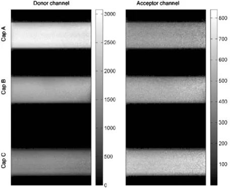
To compare the three data acquisition techniques in a real imaging situation, an image was composed with three capil-laries filled with different mixtures of the DNA constructs. Capillary A contains the OG488-ds and TMR-ds at a concen-tration of1M, which should not display any FRET. Capil-lary C contains only the OG488-10-TMR double-stranded DNA at 1M, which is expected to exhibit strong FRET. Capillary B is filled with a 1:1 mixture of the solutions used for capillaries A and C. Figure 2 shows the intensity measured in the green and red channel under excitation at760 nm. The decrease in green emission and increase in red counts from capillary A to C is clearly visible. Since the donor and accep-tor concentrations are equal between the three solutions, the only reason for this intensity variation is the occurrence of
FRET in the last two capillaries. Both the spectral images and the intensity datasets have been corrected for the flatness of the fluorescence field.
The maximum counts in the green channel under excita-tion at760 nm are on the order of 3000 photons. This is the case for all three imaging modalities. For the spectral and two-channel data acquisition, 20 frames of128⫻256 pixels with a 5-kHz pixel clock were added for a total acquisition time of 250 s. For the FLIM measurements, the acquisition time was slightly longer 共300 s兲 for a roughly equivalent number of detected photons. Note, however, that for the two intensity measurements, a second dataset at the acceptor ex-citation wavelength has to be recorded, which doubles the true FRET acquisition time.
Figure 3 shows the average counts measured in each cap-illary for the three imaging modalities. Again, the intensity image clearly shows the decrease in donor emission and the increase in acceptor emission, respectively. The emission spectra show a large change in the green part of the spectrum, but the change in donor intensity is less noticeable. The aver-aged fluorescence decays also demonstrate the increase in quenching of the donor emission in capillary B and C versus A. Note that in the imaging mode, the memory buffer on the TCSPC card limits the size of the acquisition. For our image, only 64 temporal channels have been used, compared to the 4096 in the bulk measurements from Fig. 1, thereby limiting the sensitivity of the lifetime detection in an imaging situa-tion.
The spectrally resolved data were analyzed using the FRET algorithms presented earlier. The reference images for the donor and acceptor were obtained from the OG488-ds and TMR-ds solution in hanging-drop slides under the same
im-Table 3 Comparison of the expected and measured efficiencies for
the two DNA FRET constructs using different imaging modalities. The distances are obtained from a cylindrical model of DNA.
OG488-10-TMR OG488-20-TMR r关Å兴 46.5 75.8 Etheory 0.88 0.28 Eintensity 0.74±0.2 0.32±0.08 Espectral 0.75±0.02 0.31±0.01 Elifetime 0.90±0.01 0.32±0.005
Fig. 2 Images of the three capillaries in the donor channel and acceptor channel under donor excitation共760 nm兲. Capillary A contains OG488-ds and TMR-ds at 1M共no FRET兲. Capillary C contains OG488-10-TMR 共high FRET兲, and Capillary B a 1:1 mixture of the solutions used in capillaries A and C.
aging conditions. The quantum yields for OG488 and TMR in solution are close to unity. However, the binding to the DNA modifies this, and TMR fluorescence is partially quenched by this interaction. Based on the lifetime measurements, a QYa
of 0.63 was calculated. The fractions of donor and acceptor emission measured with the two channel scheme were esti-mated using reference curves for the filters for the intensity measurements, and it is also used to account for the difference in sensitivity of the PMT in the green and red parts of the spectrum. For the spectral imaging, the sensitivity in the red is further reduced by the grating of the spectrometer, which is blazed at 400 nm. The transmission values TF and TD are
equal to one, as no neutral density filter has been used.
Over-all, the G value for the two channel setup was found to be 19% for the two channel mode, 18% for the spectral imaging converted in two channel, and 21% for the spectral imaging with spectral decomposition. This means that for every five photons collected in the green channel, only one is measured in the red.
The FRET2 index was calculated for each pixel of the image using the four algorithms presented earlier. Figure 4共a兲 shows the average values and standard deviation calculated from each algorithm in the respective capillaries. For capillary A, the expected average should be zero; however, every algo-rithm delivers a slightly higher average FRET2 index. For each method tested, the FRET2 index increases almost lin-early for capillary B and C. Figures 4共b兲 and 4共c兲 represent the histograms of the FRET2 retrieved in each capillary. The distributions retrieved with the lifetime algorithm are notice-ably sharper than for the intensity-based methods.
The lifetimes can provide more information about the FRET construct present in the image. The global fitting algo-rithm was applied to a dataset formed by the image shown in Fig. 2, as well as a second FLIM image containing three cap-illaries, one共D兲 with no FRET similar to capillary A, and two containing mixtures共capillary E: 3:1 and capillary F: 7:1兲 of the solution used in capillaries A and C. The algorithm re-trieved two lifetimes of 3.38 and 0.58 ns, and the ratio of fretting over total dye共R2= 1.106兲. The average values of the ratio as well as the histogram of the ratio are shown in Fig. 5. The expected ratio for capillaries A and D is, of course, zero. A ratio of one is expected for capillary C. However, as mea-sured in the bulk solution, OG488-10-TMR exhibits a bipha-sic decay, and only 69% of the population relaxes with the fast time constant. Consequently, the ratio obtained by the global fit also reflects a lower fretting population. Finally, the standard deviations of FRET2 index measurements using these four approaches are shown in Fig. 6.
5 Discussion
The efficiencies calculated from all three modalities used for the measurement of the bulk DNA solutions are consistent with the expected efficiencies. In the present case, the bleed-through of the acceptor in the green channel is reduced to a minimum. Therefore, the photon counts in this channel are directly proportional to the emission of the donor. These re-sults are affected by one experimental artifact due to the pres-ence of a nonFRETting donor. This can be caused either by unannealed donor strands or annealed donor strands with a complementary strand lacking the acceptor dye. This signal skews the efficiency calculation, and FRET efficiencies are lower than expected, especially at short distances where the quenching is important.
Only the lifetime measurements can distinguish between the FRETting and nonFRETting populations of the donor, be-cause they exhibit different lifetimes. This phenomenon is predominantly seen in the OG488-10-TMR, where a double exponential decay is required to analyze the fluorescence de-cay properly. For the OG488-20-TMR sample, a double ex-ponential can be used to fit the data. It does not provide any noticeable improvement of the fit, because the two time con-stants are very close and only a fraction of the decay 共up to 6.5 ns兲 is acquired.
Fig. 3 Average photon counts in each capillary with the different
im-aging modalities for capillaries A, B, and C:共a兲 two-channel measure-ment,共b兲 spectral imaging, and 共c兲 fluorescence lifetime microscopy.
Doubly labeled DNA systems are used to quantify the ac-curacy and precision of intensity, spectral, lifetime FRET measurement approaches. While these DNA constructs do not recapitulate the complexity of measuring protein interactions
in cells where FRET efficiency can be affected by environ-mental factors such as temperature and pH, the FRET effi-ciencies of these DNA constructs can be theoretically pre-dicted and precisely controlled experimentally by varying the distance between the fluorophores. FRET has already been measured in many similar doubly labeled DNA systems.39–43 A true comparison between all these studies is somewhat dif-ficult, because the dyes and strands are not identical. How-ever, the distances retrieved are comparable, which means that the overall energy process is not affected greatly by these slight dissimilarities. Therefore, the DNA construct is an ex-cellent test system to evaluate the accuracy of these different imaging techniques to retrieve FRET in a microscopy image. As discussed in Thaler et al.32the development of FRET tech-nology requires a set of well-quantified reference standard samples, against which the utility of different imaging tech-nologies and probe pairs can be evaluated. We show that these doubly labeled DNA systems are very valuable in evaluating different FRET imaging modalities; we expect that they can also be used in the evaluation of different FRET fluorophore pairs and can quantify their Förster distances.
Fig. 4 共a兲 Mean FRET 2 indices retrieved in each capillary with differ-ent data analysis techniques. 1. Two-channel algorithm, 2. spectral imaging with spectral decomposition, 3. spectral imaging split for two channel algorithm, and 4. global fitting of FLIM data.共b兲 FRET 2 his-togram for spectral imaging with decomposition共solid lines兲 and two-channel共dotted line兲 imaging in capillaries A, B, and C 共in ascending order兲. 共c兲 FRET 2 histogram for FLIM in capillaries A, B, and C.
Fig. 5 共a兲 Ratio coefficients retrieved using the global fitting algorithm
in six capillaries with various mixtures of OG488-ds and OG488-10-TMR共see text兲. The two lifetimes recovered are 3.38 and 0.58 ns. 共b兲 Mean ratio coefficients obtained from the global fit plotted as function of the expected ratio coefficient. The solid line is a linear regression with a slope of 0.79 and offset of 0.1.
The use of the three capillaries allowed us to form an image containing different amounts of FRET in a well-controlled manner. This technique had one minor shortcom-ing. Due to the relatively large size of these capillaries 共100-m external dimension兲, the scanning area has to be large. To collect the largest fraction of emitted photons, an objective with a large NA is needed. The25⫻ objective cho-sen for these experiments is a good compromise between high NA共0.8兲 and low magnification. It was still necessary to scan the laser beam at large angles to cover a distance of more than 250m. As a result, the collection efficiency in the periphery of the image is decreased by a factor of 4. This artifact is accounted for by using a reference image from a fluorescent solution with the same scanning parameters. Figure 2 shows that this correction is effective, because the intensity through-out the capillaries is relatively uniform. However, the photon counting noise is increased by that procedure. The distribution of the photon counts is expected to obey Poisson statistics, but the standard deviations for each capillary in the images are roughly 10 to 20% larger than the square root of the mean.
The standard deviation for FRET2 due only to Poisson noise is only marginally smaller than the measured FRET2 standard deviation. Therefore, this distribution in FRET2 in-dices is due to the intrinsic noise of the measurement and is not introduced by experimental artifacts. Improvement in the FRET2 signal could be obtained by increasing the acquisition time or the detected photon flux.
The results obtained here are clearly dependent on the ex-perimental conditions and instrument used. We are fortunate to have a single instrument that combines three different types of imaging techniques and therefore allows an accurate com-parison of these modalities. Other setups dedicated to one of these imaging techniques might be more sensitive than our microscope. However, we try to draw some general conclu-sions on the implications of our results for in vivo FRET imaging.
The FRET2 index calculated is very sensitive to the value of the G variable. Because we used different detection schemes, we had to determine its value with precision. How-ever, for most users working on a single instrument with a given FRET pair, an inaccurate G value will not prevent a relative comparison of the measured FRET2 indices. A pre-cise quantification of G will be necessary only if different setups are used, or in cases where the quantum yields of the dyes are dependent on the experimental conditions. Other al-gorithms use different correction normalization factors, which can be more readily available than quantum yields, such as the respective absorbance of the acceptor and the donnor. Re-cent studies from Hoppe, Christensen, and Swanson, and Bonamy, Guiochon-Mantel, and Allison, allow to recover sto-ichiometry of FRET interactions, but require the measurement of a reference FRET construct, which is not always available for in vivo experiments.21,44
For intensity-based techniques, the error in the FRET2 in-dex determination is only marginally dependent on calibration factors such as G and bleed-through calibrations共which can be obtained from a large number of reference samples兲, but mostly arises from the addition of multiple images, each hav-ing an intrinsic noise. Moreover, the algorithm relies mostly on the FRET image共daF兲, which is usually the noisiest of the
dataset. To enhance the quality of this image, the brightness of the red fluorophore can be improved by optimizing two ex-perimental parameters: the quantum yield and the detection efficiency. In the present case, the detection in the red is not optimum due to the PMT detectors. CCD-based or avalanche photodiode-based detection have better quantum efficiencies and would improve the sensitivity in the red part of the spec-trum. TMR is an excellent red fluorophore with a quantum yield close to unity. Unfortunately, it was slightly quenched by the DNA, which decreased its quantum yield to 0.63. This is still a respectable quantum yield for a red fluorophore. It is, for instance, four times larger than the quantum yield of Cy3 often used to tag antibodies in FRET experiments, and is com-parable to DsRed 共0.79兲 but still much larger than mRFP1 0.25.10
The noise in all the images is directly linked to the number of photons collected. Therefore, the signal collected by the detector must be maximized. In two-channel imaging, spectral bleed-through is often eliminated by choosing narrow spectral windows, but this often results in increased photon loss. One should, on the contrary, try to maximize the fluorescence col-lected and rely on the Gordon’s algorithm to efficiently ac-count for the bleed-through. Spectral imaging is the natural extension of this observation, because all the emitted fluores-cence is collected without any light losses due to filters and beamsplitters. However, our setup suffers from other losses that are present in the spectral imaging path. Thus, the mea-sured green intensities in the green channel or in the green part of the spectrum are relatively similar.
The difference between the two types of data analysis of the spectral images is minor. In capillary A, the green emis-sion dominates the spectrum and the TMR emisemis-sion appears only as a shoulder on the Oregon Green emission. Resolving precisely the contribution of the red fluorophore with spectral decomposition is hard under those conditions. In capillary C, where the two fluorophores are contributing more equally to the emission, the spectral decomposition performs more effi-ciently and the measured standard deviation is better than the one obtained from a simple split in green and red contribu-tions. In cases where the two dyes have closer emission
spec-Fig. 6 Standard deviation of the FRET 2 index in each capillary as a
function of the data analysis algorithm: 1. global fitting of FLIM data, 2. two-channel algorithm, 3. spectral imaging with spectral decompo-sition, and 4. spectral imaging split for two-channel algorithm. The dashed bars correspond to the calculated FRET2 error based on Pois-son statistics for the intensity measurements.
tra, or if a third species 共autofluorescence兲 is present in the image, it might also be more advantageous to use the spectral decomposition technique. Thaler et al. have developed an el-egant technique that couples the spectral decomposition of the image set directly with the calculation of the FRET efficiency based on linear unmixing.32
The FLIM clearly delivers errors two to three times smaller than the measured standard deviation obtained with other techniques. The advantage of this modality is that it relies only on the measurement of the donor image 共ddF兲,
which is the brightest image of the dataset. FLIM can even be used to monitor the energy transfer process toward nonfluo-rescing acceptors.
The other main advantage of lifetime imaging is that the proportion of interacting versus free donors in the image can be extracted using a global fitting algorithm. From the two lifetimes of the image, the distance separating the two dyes 共50 Å兲 can be calculated, which is close to the expected dis-tance discussed previously共Table 3兲. For capillaries A and D, where a ratio of zero is expected, there is an offset due to the fitting of a double exponential decay to noisy decay curves, which results in an overestimation of the contribution of the faster decay component. This artifact was already observed in other global fitting analyses.34 For the other capillaries, the ratio, increases linearly with the expected ratio, with an error in the determination of the interacting ratio on the order of 10%. This can be improved by lengthening the acquisition time and thus improving the signal-to-noise ratio. Addition-ally, one could implement a global fitting algorithm that also takes into account the fluorescence decay of the acceptor. This might improve the resolution of the FRET lifetime and thus the characterization of the interaction ratio.
One often mentioned criticism addressed to FLIM imaging is the fact that the image acquisition is slow.32Acquiring an image with enough photons detected in each pixel to build a good lifetime histogram can take up to five to ten minutes, depending on the sample. A bright sample delivers 106photons/ sec. In 5 min, one counts roughly
4500 photons per pixel in a 256⫻256 image, which is more than enough to use in a global fitting routine.
The acquisition time is directly linked to the dye concen-tration in the sample and the excitation intensity: the larger the emitted photon flux, the shorter the imaging time. This holds true until one reaches saturation of the detector. Due to the time correlation electronics, saturation is reached at lower light levels for the FLIM acquisition than for intensity-based detection, where it is even possible to work in dc mode in-stead of photon counting mode to accommodate the highest intensity levels. However, in common FRET experiments where FP constructs are artificially produced by cells, it is important not to overexpress these proteins to retain physi-ologically relevant concentration levels. Moreover, excitation energies are also kept low to avoid photobleaching and other unwanted side effects. Therefore, typical fluorescence photon fluxes in those experiments are well within the range where TCSPC are operational. Within this range, we have shown that they provide the most accurate way to quantify FRET.
6 Conclusion
Using a doubly labeled DNA strand, it is possible to generate a FRET construct with a fixed efficiency. For a separation of
ten base pairs between Oregon Green 488 共the donor兲 and tetramethylrhodamine共the acceptor兲, an efficiency of 80% is obtained. This construct is used in a real imaging situation using an image formed by microcapillaries containing differ-ent ratios of the FRET construct and non-FRETting DNA strands. Four different analysis methods are used. The first uses a two-channel detection scheme based on Gordon’s algo-rithm, which allows the FRET2 index to be calculated and a measure of the amount of FRET occurring in each pixel of the image. The distribution of the FRET2 values are found to be mainly governed by Poisson noise, thus an increase in accu-racy would require a longer acquisition time or a higher pho-ton flux. The second imaging modality used is spectral imag-ing, where two different analysis methods are employed. Both yield slightly improved distribution than the simple two-channel measurements. The spectral decomposition optimiza-tion employed could prove very powerful in systems with larger spectral overlap. Further technical improvements could also help this type of analysis by improving the detection efficiency in the red part of the spectrum. Finally, the FLIM images provide the best assessment of the FRET2 index. Based on a global fitting algorithm, this analysis also delivers significantly smaller uncertainty on the FRET2 index than other methods. Since the detection and quantification of protein-protein interactions in cells are often limited by ex-periment precision, lifetime approach should be considered in certain cases despite the inherent instrument complexity. Fur-ther, the FLIM approach also allows the ratio of FRET con-struct over total green dye in each pixel of the image to be measured, allowing the quantification of the fraction of inter-acting proteins in cells.
Acknowledgment
This work has been supported by the National Institute of Health grant NIHPOIHL64858.
References
1. B. S. Gaylord, M. R. Massie, S. C. Feinstein, and G. C. Bazan, “SNP detection using peptide nucleic acid probes and conjugated polymers: applications in neurodegenerative disease identification,” Proc. Natl.
Acad. Sci. U.S.A. 102共1兲, 34–39 共2005兲.
2. D. J. Lichlyter, S. A. Grant, and O. Soykan, “Development of a novel FRET immunosensor technique,” Biosens. Bioelectron. 19共3兲, 219– 226共2003兲.
3. H. J. Youn, E. Terpetschnig, H. Szmacinski, and J. R. Lakowicz, “Fluorescence energy transfer immunoassay based on a long-lifetime luminescent metal-ligand complex,” Anal. Biochem. 232共1兲, 24–30 共1995兲.
4. X. Zhuang and M. Rief, “Single-molecule folding,” Curr. Opin.
Struct. Biol. 13共1兲, 88–97 共2003兲.
5. S. Weiss, “Measuring conformational dynamics of biomolecules by single molecule fluorescence spectroscopy,” Nat. Struct. Biol. 7共9兲, 724–729共2000兲.
6. E. A. Jares-Erijman and T. M. Jovin, “FRET imaging,” Nat.
Biotech-nol. 21共11兲, 1387–1395 共2003兲.
7. A. K. Kenworthy, “Imaging protein-protein interactions using fluo-rescence resonance energy transfer microscopy,” Methods 24共3兲, 289–296共2001兲.
8. R. B. Sekar and A. Periasamy, “Fluorescence resonance energy trans-fer共FRET兲 microscopy imaging of live cell protein localizations,” J.
Cell Biol. 160, 629–633共2003兲.
9. J. D. Mills, J. R. Stone, D. G. Rubin, D. E. Melon, D. O. Okonkow, A. Periasamy, and G. A. Helm, “Illuminating protein interactions in tissue using confocal and two-photon excitation fluorescence reso-nance energy transfer microscopy,” J. Biomed. Opt. 8共3兲, 347–356 共2003兲.
10. R. E. Campbell, O. Tour, A. E. Palmer, P. A. Steinbach, G. S. Baird, D. A. Zacharias, and R. Y. Tsien, “A monomeric red fluorescent protein,” Proc. Natl. Acad. Sci. U.S.A. 99共12兲, 7877–7882 共2002兲. 11. G. S. Baird, D. A. Zacharias, and R. Y. Tsien, “Biochemistry,
mu-tagenesis, and oligomerization of DsRed, a red fluorescent protein from coral,” Proc. Natl. Acad. Sci. U.S.A. 97共22兲, 11984–11989 共2000兲.
12. R. Y. Tsien, “The green fluorescent protein,” Annu. Rev. Biochem. 67, 509–544共1998兲.
13. M. Zimmer, “Green fluorescent protein共GFP兲: Applications, struc-ture, and related photophysical behavior,” Chem. Rev. (Washington,
D.C.) 102, 759–781共2002兲.
14. M. Tramier, I. Gautier, T. Piolot, S. Ravalet, K. Kemnitz, J. Coppey, C. Durieux, V. Mignotte, and M. Coppey-Moisan, “Picosecond-hetero-FRET microscopy to probe protein-protein interactions in live cells,” Biophys. J. 83共6兲, 3570–3577 共2002兲.
15. T. Kohl, K. G. Heinze, R. Kuhlemann, A. Koltermann, and P. Schwille, “A protease assay for two-photon crosscorrelation and FRET based solely on fluorescent proteins,” Proc. Natl. Acad. Sci.
U.S.A. 99共19兲, 12161–12166 共2002兲.
16. D. R. Larson, Y. M. Ma, V. M. Vogt, and W. W. Webb, “Direct measurement of Gag-gag interaction during retrovirus assembly with FRET and fluorescence correlation spectroscopy,” J. Cell Biol. 162, 1233–1244共2003兲.
17. L. Tremuth, S. Kreis, C. Melchior, J. Hoebeke, P. Ronde, S. Plancon, K. Takeda, and N. Kieffer, “A fluorescence cell biology approach to map the second integrin-binding site of talin to a 130-amino acid sequence within the rod domain,” J. Biol. Chem. 279共21兲, 22258– 22266共2004兲.
18. G. W. Gordon, G. Berry, X. H. Liang, B. Levine, and B. Herman, “Quantitative fluorescence resonance energy transfer measurements using fluorescence microscopy,” Biophys. J. 74, 2702–2713共1998兲. 19. C. Berney and G. Danuser, “FRET or no FRET: A quantitative
study,” Biophys. J. 84, 3992–4010共2003兲.
20. M. Elangovan, H. Wallrabe, Y. Chen, R. N. Day, M. Barroso, and A. Periasamy, “Characterization of one- and two-photon excitation fluo-rescence resonance energy transfer microscopy,” Methods 29共1兲, 58–73共2003兲.
21. A. Hoppe, K. Christensen, and J. A. Swanson, “Fluorescence reso-nance energy transfer-based stoichiometry in living cells,” Biophys. J.
83, 3652–3664共2002兲.
22. Z. Xia and Y. Liu, “Reliable and global measurement of fluorescence resonance energy transfer using fluorescence microscopes,” Biophys.
J. 81, 2395–2402共2001兲.
23. N. Mochizuki, S. Yamashita, K. Kurokawa, Y. Ohba, T. Nagai, A. Miyawaki, and M. Matsuda, “Spatio-temporal images of growth-factor-induced activation of Ras and Rap1,” Nature (London)
411共6841兲, 1065–1068 共2001兲.
24. M. Elangovan, R. N. Day, and A. Periasamy, “Nanosecond fluores-cence resonance energy transfer-fluoresfluores-cence lifetime imaging mi-croscopy to localize the protein interactions in a single living cell,” J.
Microsc. 205, 3–14共2002兲.
25. P. J. Verveer, F. S. Wouters, A. R. Reynolds, and P. I. H. Bastiaens, “Quantitative imaging of lateral ErbB1 receptor signal propagation in the plasma membrane,” Science 290, 1567–1570共2000兲.
26. B. J. Bascskai, J. Skoch, G. A. Hickey, R. Allen, and B. T. Hyman, “Fluorescence resonance energy transfer determinations using multi-photon fluorescence lifetime imaging microscopy to characterize amyloid-beta plaques,” J. Biomed. Opt. 8共3兲, 368–375 共2003兲.
27. Y. Chen and A. Periasamy, “Characterization of two-photon excita-tion fluorescence lifetime imaging microscopy for protein localiza-tion,” Microsc. Res. Tech. 63, 72–80共2004兲.
28. L. Stryer and R. P. Haugland, “Energy transfer: a spectroscopic ruler,” Proc. Natl. Acad. Sci. U.S.A. 58, 719–726共1967兲.
29. P. Wu and L. Brand, “Resonance energy transfer: methods and appli-cations,” Anal. Biochem. 218共1兲, 1–13 共1994兲.
30. G. H. Patterson, D. W. Piston, and B. G. Barisas, “Förster distances between green fluorescent protein pairs,” Anal. Biochem. 284, 438– 440共2000兲.
31. W. R. Zipfel, R. M. Williams, R. Christie, A. Y. Nikitin, B. T. Hy-man, and W. W. Webb, “Live tissue intrinsic emission microscopy using multiphoton-excited native fluorescence and second harmonic generation,” Proc. Natl. Acad. Sci. U.S.A. 100共12兲, 7075–7080 共2003兲.
32. C. Thaler, S. V. Koushik, P. S. Blank, and S. S. Voge, “Quantitative multiphoton spectral imaging and its use for measuring resonance energy transfer,” Biophys. J. 89共4兲, 2736–2749 共2005兲.
33. T. Haraguchi, T. Shimi, T. Koujin, N. Hashiguchi, and Y. Hiraoka, “Spectral imaging fluorescent microscopy,” Genes Cells 7, 881–887 共2002兲.
34. S. Pelet, M. J. Previte, L. H. Laiho, and P. T. So, “A fast global fitting algorithm for fluorescence lifetime imaging microscopy based on im-age segmentation,” Biophys. J. 87共4兲, 2807–2817 共2004兲.
35. P. J. Verveer, A. Squire, and P. I. H. Bastiaens, “Global analysis of fluorescence lifetime imaging microscopy data,” Biophys. J. 78, 2127–2137共2000兲.
36. C. Buehler, K. H. Kim, U. Greuter, N. Schlumpf, and P. T. So, “Single-photon counting multicolor multiphoton fluorescence micro-scope,” J. Fluoresc. 15共1兲, 41–51 共2005兲.
37. E. Rusinova, V. Tretyachenko-Ladokhina, O. E. Vele, D. F. Senear, and J. B. Alexander Ross, “Alexa and Oregon Green dyes as fluores-cence anisotropy probes for measuring protein and protein-nucleic acid interactions,” Anal. Biochem. 308共1兲, 18–25 共2002兲. 38. J. R. Unruh, G. Gokulrangan, G. S. Wilson, and C. K. Johnson,
“Fluorescence properties of fluorescein, tetramethylrhodamine, and Texas Red linked to a DNA aptamer,” Photochem. Photobiol. 81共3兲, 682–690共2005兲.
39. A. A. Deniz, M. Dahan, J. R. Grunwell, T. Ha, A. E. Faulhaber, D. S. Chemla, S. Weiss, and P. G. Schultz, “Single-pair fluorescence reso-nance energy transfer on freely diffusing molecules: observation of Forster distance dependence and subpopulations,” Proc. Natl. Acad.
Sci. U.S.A. 96, 3670–3675共1999兲.
40. R. M. Clegg, “Fluorescence resonance energy transfer and nucleic acids,” Methods Enzymol. 211, 353–388共1992兲.
41. R. M. Clegg, “Observing the helical geometry of double-stranded DNA in solution by fluorescence resonance energy transfer,” Proc.
Natl. Acad. Sci. U.S.A. 90, 2994–2998共1993兲.
42. K. M. Parkhurst and L. J. Parkhurst, “Donor-acceptor distance distri-bution in a double-labeled fluorescent oligonucleotide both as a single strand and in duplexes,” Biochemistry 34, 293–300共1995兲. 43. K. Toth, V. Sauermann, and J. Langowski, “DNA curvature in
solu-tion measured by fluorescence resonance energy transfer,”
Biochem-istry 37, 8173–8179共1998兲.
44. G. M. Bonamy, A. Guiochon-Mantel, and L. A. Allison, “Cancer promoted by the oncoprotein v-ErbA may be due to subcellular mis-localization of nuclear receptors,” J. Mol. Endocrinol. 19共5兲, 1213– 1230共2005兲.