Combustion synthesis of fullerenes
and fullerenic nanostructures
by
Anish Goel
B.S.E. in Chemical Engineering University of Michigan, 1997
M.S. in Chemical Engineering Practice Massachusetts Institute of Technology, 1999
Submitted to the Department of Chemical Engineering in partial fulfillment of the requirements for the degree of
Doctor of Philosophy
at the
Massachusetts Institute of Technology
June 2002
MASSACHU INSUTE
OF TECHNOLOGY
JUN 0 2 2005
LIBRARIES
© 2002 Massachusetts Institute of Technology All rights reserved
Signature of Author:
Department of Chemical Engineering -March 2002
Certified by:
Accepted by:
Jack B. Howard Hoyt C. Hottel Professor of Chemical Engineering Thesis Supervisor
MASSA(HUSETTSSTTUTE - I
MASSACHUSETTS INSTITUTE
OF TECHNOLOGY
lJ.IU.li.l tgJ lllU1 lll iI Professor of Chemical Engineering Chairman, Committee for Graduate Students
Combustion synthesis of fullerenes and fullerenic nanostructures by Anish Goel
Submitted to the Department of Chemical Engineering on 21 March 2002 in partial fulfillment of the requirements for the degree of Doctor of Philosophy in Chemical Engineering Abstract
Fullerenes are molecules comprised entirely of sp2-bonded carbon atoms arranged in
pentagonal and hexagonal rings to form a hollow, closed-cage structure. Buckyballs, a subset which contains C60and C70, are single-shell molecules while fullerenic
nanostructures can contain many shells and over 300 carbon atoms. Both fullerenes and nanostructures have an array of applications in a wide variety of fields, including medical and consumer products. Fullerenes were discovered in 1985 and were first isolated from the products of a laminar low-pressure premixed benzene/oxygen/argon flame operating at fuel-rich conditions in 1991. Flame studies indicated that fullerene yields depend on operating parameters such as temperature, pressure, residence time, and equivalence ratio. High-resolution transmission electron microscopy (HRTEM) showed that the soot contains nanostructures, including onions and nanotubes.
Although flame conditions for forming fullerenes have been identified, the process has not been optimized and many flame environments of potential interest are unstudied. Mechanistic characteristics of fullerene formation remain poorly understood and cost estimation of large-scale production has not been performed. Accordingly, this work focused on: 1) studying fullerene formation in diffusion and premixed flames under new conditions to identify optimal parameters; 2) investigating the reaction of fullerenes with soot; 3) positively identifying C60molecules in HRTEM by tethering them to carbon
black; and 4) providing a cost estimation for industrial fullerenic soot production. Samples of condensable material from laminar low-pressure benzene/argon/oxygen diffusion flames were collected and analyzed by high-performance liquid chroma-tography (HPLC) and HRTEM. The highest concentration of fullerenes in a flame was always detected just above the height where the fuel is consumed. The percentage of fullerenes in condensable material increases with decreasing pressure and the fullerene content of flames with similar cold gas velocities shows a strong dependence on length. A shorter flame, resulting from higher dilution or lower pressure, favors the formation of fullerenes rather than soot, exhibited by the lower amount of soot and precursors in such flames. This indicates a stronger correlation of fullerene consumption to soot levels than of fullerene formation to precursor concentration. The maximum flame temperature seems to be of minor importance in formation. The overall highest amount of fullerenes was found for a surprisingly high dilution of fuel with argon. The HRTEM analysis showed an increase of the curvature of the carbon layers, and hence increased fullerenic character, with increasing distance from the burner up to the point of maximum fullerene concentration, after which it decreases, consistent with the HPLC analysis. The soot shows highly ordered regions that appear to have been cells of fullerenic nanostructure formation. The samples also included fullerenic nanostructures such as tubes and spheroids including highly-ordered multilayered or onion-like structures. Studies of turbulent-like benzene/oxygen/argon diffusion flames showed that these flames produce
fullerenes over a wider range of heights than laminar flames but with lower yields. No discernible trend could be detected in the data and the fullerene results were not easily reproducible indicating that such flames are not suitable for fullerene formation.
Soot samples were also collected from a well-characterized laminar premixed benzene/oxygen/argon flat flame under new conditions and analyzed by HPLC and HRTEM. Flame studies using secondary injections of benzene or acetylene show that two-stage flames are unsuitable for fullerene production. It seems that secondary fuel has an adverse effect on the formation of fullerenes and creates conditions that are similar to the early stages of a single-stage flame prior to soot formation. This means that fuel must go through the combustion process to form fullerenes and that they cannot be formed simply by organic pyrolysis. Additionally, fullerene data collected in this study show significantly higher yields than in a previous study and the absence of a concentration drop-off. The coexistence of fullerenes and soot does not support but also does not rule out that fullerenes are consumed by soot, as was suggested by diffusion flame data.
Given the discrepancy in the data, fullerene consumption was studied in experiments involving pure fullerenes being sublimated into a passing argon gas stream. This gas stream then passed through a carbon black bed. As the fullerenes passed through the bed, a certain percentage reacted with the surface of the particles and the non-reacted material was collected downstream. Experiments at different temperatures indicate that fullerenes are indeed consumed by soot particles but that the consumption is quite slow. The rate coefficient obtained resembles those seen for surface diffusion controlled reactions or for heterogenous reactions. Extrapolation of the reaction coefficient to flame conditions would indicated that this type of fullerene consumption is not nearly enough to explain the consumption observed in fullerene-forming flames, meaning that fullerenes are consumed by other mechanisms.
HRTEM analysis of carbon black with and without tethered fullerenes shows that fullerenes can in fact be observed in TEM micrographs. In this experiment,
functionalized C60molecules were attached to the surface of carbon black particles with a
chemical tether. The resulting compound was analyzed by HRTEM and compared with similar analysis of untreated carbon black. The post-treatment carbon black not only has an order of magnitude greater concentration of apparent fullerene structures but size distribution data shows a significant peak at the C60diameter for the treated sample
whereas no peak is observed for the untreated sample. This indicates that the fullerenes have indeed been attached to the particle surface and that they can definitively be seen in images produced from HRTEM.
Lastly, a model was built to estimate the cost of the large scale production of
fullerenic soot. This model was based on current carbon black technology and takes into account operating parameters specific for fullerene production. Sensitivity analyses performed on the model indicate that soot yield and fuel price are the most important factors in determining production cost while electricity costs are minimally important. It was seen that operating pressure and equipment lifetime are negligible in the final cost.
Overall, combustion holds immense promise to be a much cheaper and more efficient alternative to the current method of commercial fullerene production.
Thesis Supervisor: Jack B. Howard
to ma, pa, & rink
who have catapulted me above the clouds and allowed me to touch the sky
Acknowledgements
Although many of my partners in crime would prefer to remain blissfully anonymous, I will nevertheless try to identify as many as my weary mind will allow. I apologize in advance for any
omissions as they are purely unintentional. The folks mentioned here are primarily responsible for my successes but all the mistakes and shortcomings are completely my own.
I of course owe a great deal to my advisor, Prof. Jack Howard. Whether in combustion or the world at-large, his constructive support, dignified approach, and walking authority have set an example that I can only hope to live up to. His imminent departure from MIT reminds me how fortunate I've been to have had the opportunity to work with such a legendary and respected
individual. Like a seasoned jedi with his novice apprentice, he has guided me in the right direction yet allowed me to search out my own path. I wish I knew a bigger word than 'thanks'.
For undertaking the unenviable task of serving on my thesis committee, I am indebted to Prof. John Vander Sande, Dr. Art Lafleur, and Prof. Bill Green. All have made valuable contributions and suggestions when they were sorely needed. I especially recognize Prof. Vander Sande, joined by his masters of TEM Lenore Rainey, Paulo Ferreira, and Paula Jardim, for their boundless insight and enthusiasm on a plethora of TEM images and collaborations. The expert chemical analyses provided by Koli Taghizadeh, Elaine Plummer, and John LaRusso were similarly invaluable to me and Peter Morley brought all my half-baked designs to vibrant life. Profs. Alan Hatton and Jefferson Tester also deserve special thanks for keeping me happy when I was mired in the bureaucracies of the department.
For my buddies in the basement, my illustrious colleagues of fire, the dungeon dwellers of Building 66, what can I say? Their discussions, insight, intrigue, and general merriment have sustained me during this arduous trek. Without them, this thesis would be postponed indefinitely. Members current and former include Murray Height, Patty Sullivan, Henning Richter, Mike Timko, Gerardo Ferreiro, Jin Qian, Heather Stem, Jason Ploeger, Liz Gron, Peter Hebgen, Isidro Griful, Josh Taylor, David Kronholm, Joe Schanzenbecher, Quico Ayala, Wolfgang Voelcker, Thilo Lehre, and Tony Modestino. I will sadly miss our many moons of shared jubilation and commiseration.
I am also beholden to a group I call the 'circle of power' who have helped me in ways that go beyond research and academics. Ilea Mathis, Anna Di Maria, Craig Abernethy, Carol Phillips, Arline
Benford, Susan Lanza, Barbara Driscoll, Patsy Sampson, Emmy Snyder, Suzanne Easterly, Annie Fowler, and Elaine Aufiero do not possess the title of professor, but in most ways, they have more authority - a student couldn't ask for a more devoted bunch. I owe them my livelihood at bonny MIT.
I could never adequately express my appreciation for my family. Always a bedrock of support and encouragement and the source of countless examples to follow, they are titans of integrity, generosity, and success and I am but a mouse, struggling to keep up. They have known me better than I have known myself- never believing (and never letting me forget) my now infamous senior-year comment, "They couldn't pay me enough to go to grad school." So to Mom, Dad, Anuj, and Stacy - you have helped me more than you can ever know.
And finally, to all my sanity-keepers over the years. Some are honorary dungeon dwellers and some have never set foot on MIT campus, but they have all helped me in special ways that can never be tangibilized. In no particular order, they are: Amy Kanellis, Randall Urbance, Brian Makins, Jannise Obst, David Matheu, Christa Beranek, David Collins, the indomitable Paul Fernandez, John O'Quinn, Wenny Jean, Mutsumi Yoshida, Jean Dubay, Sara Soderstrom, Jean Bender, Ian Das, Jamie Bechtel, Jim Bielenberg, Paul Yelvington, April Ross, Ley Richardson, Kim Bryan, Ian Zacharia, Kevin Dorfman, Audrey Johnson, Chris Martin, Eric Nelson, Chen Wang, Zhitao Cao, Thomas Epps, Gia Schneider, Javier Femenia, Erika Martin, Lacey Southerland, Shawn Cole, Ana Sala, Blanca San Miguel, Beatriz Escudero, Mariah Devereux, Silvia Roa, Brian Forster, Parag Desai, Vicki Green, Kym Ahrens, Nitin Mathur, Neil Aggarwal, and all my family in the homeland and abroad.
A last note of gratitude for the financial support from the National Aeronautics and Space Administration (Grant No. NAG3-1979) and their Graduate Student Researchers Program and from the Division of Chemical Sciences (Grant No. DE-FG02-84ER 13282), Office of Basic Energy Sciences, Office of Energy Research, United States Department of Energy.
Table of Contents
1 Introduction ... 13
1.1 Background ... 13
1.1.1 Formation of fullerenes and nanostructures . ... 15
1.1.2 Fullerene properties and reactivity ... 17
1.1.3 Applications ... 19
1.2 Fullerene formation in flames ... 20
1.2.1 Methods of production ... 20
1.2.2 Fullerene formation mechanisms ... 21
1.3 Nanostructure formation in flames ... 23
1.4 Commercial production of fullerenes ... 24
2 Objectives ... 26
3 Diffusion flame studies ... 27
3.1 Apparatus and techniques ... 27
3.1.1 Flame chamber ... 27
3.1.1.1 Flame burners ... 28
3.1.1.2 Chamber sections ... ... 32
3.1.1.3 Top plate ... 34
3.1.2 Fuel delivery ... 34
3.1.3 Quartz sampling probe ... 35
3.1.4 Fullerene extraction ... 36
3.1.5 High-performance liquid chromatography ... 37
3.1.6 High-resolution transmission electron microscopy ... 37
3.1.6.1 Qualitative analysis ... 37
3.1.6.2 Quantitative analysis ... 38
3.2 Low-flow laminar diffusion flames ... 39
3.2.1 Experimental conditions ... 39
3.2.2 Fullerene and soot results... 40
3.2.2.1 Fullerenes ... 41
3.2.2.2 Soot structure evolution ... 44
3.2.3 Discussion ... 50
3.2.3.1 Fullerenes ... 50
3.2.3.2 Soot structure evolution ... 51
3.2.4 Summary ... 52
3.3 High-flow turbulent-like diffusion flames ... 53
3.3.1 Experimental conditions ... 54
3.3.2 Fullerenes results ... 55
3.3.3 Discussion ... 57
3.3.4 Summary ... 60
3.4 Conclusions ... 60
4 Premixed flame studies.. ... 62
4.1 Apparatus and techniques ... 62
4.1.1.1 Flame burner ... 63
4.1.1.2 Chamber bottom and extension ...65
4.1.1.3 Top plate ... 66
4.1.2 Fuel delivery ... 66
4.1.3 Soot sampling... 66
4.1.4 Extraction and analysis ... .. 67
4.2 Premixed flames... 67
4.2.1 Experimental conditions ... 67
4.2.2 Fullerene results ... 67
4.2.3 Discussion ... 71
4.2.4 Summary ... 73
4.3 Premixed flames with secondary injections... 73
4.3.1 Experimental conditions ... 74
4.3.2 Fullerene Results ... 75
4.3.3 Discussion ... 77
4.3.4 Summary ... 80
4.4 Conclusions ... 81
5 Reaction rate coefficient of fullerene (C6 0) consumption by soot ... 83
5.1 Experimental system and techniques . ... 84
5.1.1 Reactor and furnace setup ... 84
5.1.2 Vapor collection... 85
5.1.3 Analysis ... 85
5.1.4 Experimental conditions ... 86
5.2 Reaction rate results ... 86
5.3 Discussion ... 88
5.4 Conclusions ... 95
6 Observations of fullerenes tethered to carbon black particles ... 96
6.1 Experimental ... 96
6.2 Tethering results... 98
6.3 Discussion ... 101
6.4 Conclusions ... 102
7 Economic cost modeling of commercial fullerenic soot plant ... 103
7.1 Model basis ... 104
7.2 Assumptions ... 106
7.2.1 Incremental changes and additions ... 106
7.2.2 Operating parameters ... 107
7.3 Cost model predictions ... 109
7.3.1 Base case cost estimate ... 110
7.3.2 Sensitivity to parameter adjustments ... 111
7.4 Model limitations ... 113
7.5 Implications for fullerene price and fullerenic soot industry ... 115
9 Recommendations ... 120
10 References ... 123
11 Appendices . ... 133
11.1 Appendix 1 - Tabulation of high-flow (turbulent) flame data ... 133
11.2 Appendix 2 - Premixed flame data and sample calculation ... 134
11.3 Appendix 3 - Calculations for fullerenic soot yield ... 136
11.3.1 Calculations from observed experimental data ... 136
11.3.2 Thermodynamic equilibrium calculations by STANJAN ... 137
11.4 Appendix 4 - Economic cost model for fullerenic soot plant ... 139
11.4.1 Spreadsheet for economic cost model - base case cost ... 139
List of Figures
Figure 1-1. Images of C60 (a) and C7 0(b) ... 14
Figure 3-1. Diffusion flame chamber with burner and flame sampling probe ... 28
Figure 3-2. Low-flow diffusion flame burner ... 29
Figure 3-3. Burner caps with varying outlet diameters ... 30
Figure 3-4. High-flow diffusion flame burner: side-view (a); top-view (b); and cut-away side-view with nozzle attached (c) ... 31
Figure 3-5. High-flow flame burner cover: side-view (a); and top-view (b) ... 32
Figure 3-6. Bottom section of diffusion flame chamber with burner and bottom plate... 33
Figure 3-7. One of two identical top sections of diffusion flame chamber ... 33
Figure 3-8. Top plate of diffusion flame chamber ... 34
Figure 3-9. Quartz probe design ... 36
Figure 3-10. Method for quantitative analysis of TEM images ... 38
Figure 3-11. Quantity of fullerenes C60 and C7 0 in the condensable material (a) and concentration of fullerenes C60 and C70in the cold probed gas (b) from different heights above the burner in different laminar diffusion flames at p=20 Torr ... 41
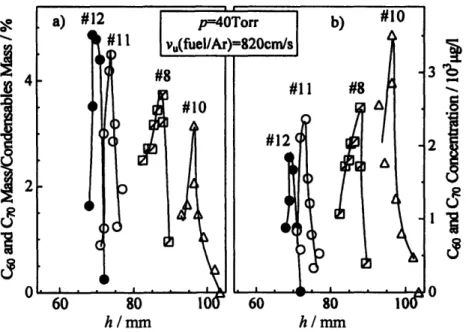
Figure 3-12. Quantity of fullerenes C60 and C7 0in the condensable material (a) and concentration of fullerenes C60and C70in the cold probed gas (b) from different heights above the burner in different laminar diffusion flames at p=40 Torr ... 43
Figure 3-13. Maximum amount of fullerenes C60and C70(a) and mass ratio of C60to C70 (b) in the condensable material at the height above the burner corresponding to maximum fullerene concentration in laminar diffusion flames, at different pressures (p) and different argon dilutions (dilAr) ... 43
Figure 3-14. Representative HRTEM image of material collected at h=75mm in flame #11 (p=40 Torr, vu(fuel/Ar)=820 cm/s, v,(oxy)=3.65 cm/s, dilAr=85.3%).... 44
Figure 3-15. Representative counted material from soot collected at h=72 mm (a), 74 mm (b), 75 mm (c), and 77 mm (d) in flame #11 (p=40 Torr, v(fuel/Ar)=820 cm/s, v(oxy)=3.65 cm/s, dilAr=85.3%) ... ... 45
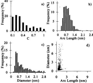
Figure 3-16. Normalized histograms of curvature (a), arc length (b), and diameter (c) and arc length versus diameter scatter plot (d) of amorphous carbon material ... 46 Figure 3-17. Normalized histograms of curvature (a), arc length (b), and diameter (c) and
h=72 mm in flame #11 (p=40 Torr, v,(fuel/Ar)=820 cm/s, v,(oxy)=3.65 cm/s,
dilAr=85.3%) ... 46
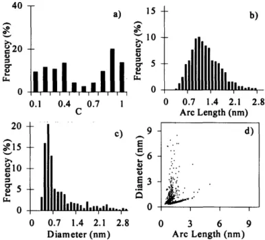
Figure 3-18. Normalized histograms of curvature (a), arc length (b), and diameter (c) and arc length versus diameter scatter plot (d) of condensable material collected at h=74 mm in flame #11 (p=40 Torr, vu(fuel/Ar)=820 cm/s, v,(oxy)=3.65 cm/s, dilAr=85.3%) ... 47
Figure 3-19. Normalized histograms of curvature (a), arc length (b), and diameter (c) and arc length versus diameter scatter plot (d) of condensable material collected at h=75 mm in flame #11 (p=40 Torr, vu(fuel/Ar)=820 cm/s, v,(oxy)=3.65 cm/s, dilAr=85.3% ) . ... 47
Figure 3-20. Normalized histograms of curvature (a), arc length (b), and diameter (c) and arc length versus diameter scatter plot (d) of condensable material collected at h=77 mm in flame #11 (p=40 Torr, vu(fuel/Ar)=820 cm/s, vu(oxy)=3.65 cm/s, dilAr=85. 3% ) ... 48
Figure 3-21. Curvature comparison for flame #11 (p=40 Torr, vu(fuel/Ar)=820 cm/s, v,(oxy)=3.65 cm/s, dilAr=85.3%) ... 49
Figure 3-22. HRTEM image of fullerenic nanostructures in condensable material collected at h=61 mm in flame #13 (p=12 Torr, v,(fuel/Ar)=820 cm/s, vu(oxy)=3.65 cm/s, dilAr=65.0%) .. ... 50
Figure 3-23. Quantity of fullerenes C60 and C70in the condensable material from different heights above burner in different turbulent diffusion flames ... 55
Figure 3-24. Concentration of fullerenes C60 and C70in the cold probed gas from different heights above burner in different turbulent diffusion flames ... 56
Figure 3-25. Mass ratio of C60to C70 in the condensable material from different heights above burner in different turbulent diffusion flames ... 56
Figure 4-1. Premixed flame chamber with burner, top plate, secondary ring injector, and flame sampling probe (from Grieco [37]) ... 63
Figure 4-2. Premixed flame burner with top view (from Grieco [37]) ... 64
Figure 4-3. Top view of large (a) and small (b) secondary ring injectors ... 65
Figure 4-4. Top section of the premixed flame chamber ... 65
Figure 4-5. Concentration of C60and C70in a premixed benzene flame (p = 40 torr, = 2.4, velocity = 25 cm/s, dilution = 10%) ... 68
Figure 4-6. Concentration of soot in a premixed benzene flame (p = 40 torr, p = 2.4, velocity = 25 cm/s, dilution = 10%) ... 69
Figure 4-7. Concentration of fullerenes in a premixed benzene flame (p = 40 torr, p = 2.4, velocity = 25 cm/s, dilution = 10%) [89] ... 70
Figure 4-8. Concentration of DCM soluble material (o) and DCM insoluble material (i) in a premixed benzene flame (p = 40 torr, 9 = 2.4, velocity = 25 cm/s, dilution = 10%) [89] ... 70 Figure 4-9. Flame gas concentration of C60in McKinnon flame and three two-stage
flames with benzene as secondary fuel ... 76 Figure 4-10. Flame gas concentration of C60in McKinnon flame and three two-stage
flames with acetylene as secondary fuel ... 76 Figure 4-11. HPLC chromatogram of soot extract from two-stage flame #3 at 60 mm
H AB ... 78 Figure 4-12. HPLC chromatogram of soot extract from McKinnon flame at 50 mm HAB.
... .... 78 Figure 4-13. HPLC chromatogram of soot extract from McKinnon flame at 5.8 mm HAB. ... 79 Figure 5-1. Schematic of equipment for study of fullerene-soot reaction ... 84 Figure 5-2. Fullerene-soot reaction rate plot - Day one data (-) with regression
(long-dashed line), Day two data (A) with regression (short-(long-dashed line), and full regression (solid line) with equation. ... 88 Figure 5-3. Predicted consumption rate of fullerenes by soot in the McKinnon flame
using fullerene and soot data from Grieco's study [89] ... 91 Figure 5-4. Predicted consumption rate of fullerenes by soot in the McKinnon flame
using fullerene data from the present study ... 92 Figure 6-1. HRTEM images of particle from pure carbon black sample ... 98 Figure 6-2. HRTEM images of particle from post-extraction tethered fullerene sample
with user-entered dashes to identify fullerene-type structures ... 99 Figure 6-3. Fullerene-type structure diameter distribution data on an absolute basis.... 100 Figure 7-1. Schematic of commercial carbon black plant ... 104 Figure 7-2. Senstivity of incremental fullerenic soot cost to soot yield and fuel price
(reactor pressure = 40 Torr and pump lifetime = 10 years) ... 111 Figure 7-3. Senstivity of incremental fullerenic soot cost to reactor pressure and pump
lifetime (soot yield = 3% and fuel price = $1.50 per gallon) ... 112 Figure 7-4. Senstivity of incremental fullerenic soot cost to reactor pressure and pump
List of Tables
Table 3-1. Laminar diffusion flame parameters ... 40
Table 3-2. Turbulent diffusion flame parameters ... 55
Table 4-1. Two-stage flame parameters.... ... 74
Table 6-1. Fullerene-type structure linear concentration data ... 99
Table 7-1. Major parameters for Donnet's carbon black production plant ... 105
1 Introduction
The family of compounds known as fullerenes consists primarily of pure carbon molecules. Each molecule contains an even number of carbon atoms between 36 and several thousand. Since fullerenes were first discovered, significant research has been performed to investigate their formation methods and potential applications. There has also been significant work to determine the mechanisms and reaction pathways that facilitate fullerene formation. Many such mechanisms have been proposed, however, none have thus far been conclusively proven or disproven. Despite this, the synthesis of fullerenes and fullerenic nanostructures through combustion of hydrocarbon fuels has been of particular interest recently and has shown potential to become a feasible method for commercial fullerene production.
1.1 Background
Fullerenes, discovered in 1985 [1], are the third form of pure carbon material behind graphite and diamond. They are made up entirely of sp2-bonded carbon atoms
which are arranged in pentagonal and hexagonal rings. The pentagonal rings cause strain within the structure which is alleviated by out-of-plane deformation or curvature at each pentagon. This curvature in the carbon structure leads to the hollow cage configuration characteristic of fullerene molecules. The most stable configuration of rings obeys the Isolated Pentagon Rule: no two pentagons in a stable fullerene can be adjacent. The number of pentagons in a molecule is fixed at twelve as this provides sufficient curvature to form a closed shell. However, the number of hexagons varies with the total number of carbon atoms according to Equation 1-1:
carbon atoms - 20
hexagons= (1-1)
2
A C60molecule, for example, contains 60 carbon atoms arranged symmetrically about a sphere into 12 pentagons and 20 hexagons. The arrangement of the pentagons on the surface determines the final cage structure. Evenly distributed pentagons will result in a sphere, as is the case for the most common isomer of C60.
The two most abundant and well-known fullerenes are C60and C70. C60is also
geodesic domes that resemble the C60molecule [1]. Only one configuration for each of
these two molecules obeys the Isolated Pentagon Rule. Being the most stable, these configurations are the most common and are shown in Figure 1-1.
(a) (b)
Figure 1-1. Images of Co (a) and C6 70 (b).
Fullerenes as small as C20and as large as C>300 have also been identified [2-4].
Those that consist of less than 300 carbon atoms are generally known as 'buckyballs' and are restricted to single-shell structures. Single metal atoms such as lanthanum or cerium can be trapped inside the cavity of these single-shell structures [5-8] creating a class of fullerenes known as endohedral fullerenes (or metallofullerenes). Giant fullerenes (C>300), however, may be single or multiple shelled. Multiple-shelled giant fullerenes are known as 'onions' as the adjacent multiple layers resemble those of an onion. Giant fullerene
'nanotubes' (or 'buckytubes') have also been identified [9]. These structures, which can be single- or multiple-shelled, consist of cylindrical walls composed entirely of
hexagonal rings capped at each end by six pentagonal rings and the necessary hexagonal rings to close the structure. Nanotubes with diameters as small as 4 A have been observed [10-12] meaning that the fullerenic caps are smaller than C60molecules, which have a
diameter of 7 A. Throughout the remainder of this work, to avoid confusion, buckyballs will be referred to simply as 'fullerenes', while onions and nanotubes will collectively be referred to as 'nanostructures'.
1.1.1 Formation offullerenes and nanostructures
Since their discovery in 1985 [1], there has been significant research into methods for synthesizing fullerenes. Kroto et al. [1] first identified fullerenes in carbon vapor from the laser ablation of graphite; Iijima used the same method to first observe C60directly
[13]. This method, however, resulted in microscopic quantities of fullerenes insufficient to provide samples for characterization and research. In 1990, fullerenes were produced in macroscopic quantities by striking an electric arc between two graphite electrodes and evaporating the graphite in a low-pressure (<100 Torr), helium atmosphere [14]. This method produces fullerenes along with a carbonaceous soot, from which the fullerenes can be separated. Although the yield of fullerenes is highly dependent on operating conditions, chamber design, and experimental technique, typical yields from this method are 10% of the collected soot [15]. At higher pressures (-500 Torr), this method has produced nanostructures and, using electrodes doped with metal, endohedral fullerenes [7]. A modified version of this graphite arc-vaporization method is the predominant method for supplying the current commercial demand for fullerenes (see Section 1.4) [15].
Other methods of fullerene synthesis include ion sputtering and electron beam evaporation of graphite [16], vaporization of graphite using highly concentrated solar heating [17, 18], resistive heating of graphite [19], laser ablation of graphite [5, 20], inductive heating of graphite [21], and carbon particle evaporation in a hybrid thermal plasma [22]. Several production methods using non-graphitic raw materials have also been studied and found to produce fullerenes. These methods include pyrolysis of naphthalene in an argon atmosphere at approximately 1000°C [23], the pyrolytic destruction of toluene in a radio frequency plasma [24], and laser-pyrolysis of benzene [25]. None of these methods, however, produce macroscopic quantities of fullerenes.
Similarly, fullerenic nanostructures can be generated under a range of conditions which were first identified in 1991 by Iijima [9] in solid deposits on the cathode of a graphite arc-vaporization apparatus operating under a pressure of 100-200 Torr. By increasing the pressure to 500 Torr, Ebbesen et al. [26] found that they could produce
arc-vaporization process [27], while Bethune et al. [28], among others, catalyzed nanotube production by using metal-doped graphite rods in arc-vaporization.
Separate from fullerenes, nanostructures have also been produced independently through arc-discharge vaporization [9-11], plasma-decomposition of benzene [29], pyrolysis of tripropylamine [12], and in a pyrolysis flame of carbon monoxide and
hydrogen [30]. They have also been produced on large-scale by the catalytic decomposition of hydrocarbons at about 1200°C [31].
Fullerenes and nanostructures have both been discovered in the products formed from the combustion of organic fuels [32-38]. The combustion synthesis of fullerenes and fullerenic nanostructures is the major focus of this work and background studies are discussed in much greater detail in Sections 1.2 and 1.3.
In addition to synthetic methods of production, fullerenes have also been found in nature. Evidence has been gathered from several different sources to indicate that the formation of fullerenes is not solely a man-made occurrence. On Earth, fullerenes, primarily C60and C70, have been extracted from two Cretaceous-Tertiary boundary sites
in New Zealand and may be the result of extensive wildfires [39]. They have also been found in fulgurite, a glassy rock that forms when lightning strikes the ground [40], in coal samples found in China [41, 42], and in shungite, a carbon-rich Precambrian rock from Karelia, Russia [43]. Fullerenes were also found in residue from the Allende meteorite [44] and the 1.85-billion-year-old Sudbury meteorite impact structure in Ontario, Canada [45]. Previous work has shown the presence of fullerene-like structures in soot from regular candle flames and wood fires thereby suggesting that fullerenes may be formed in trace quantities in such flames [37]. There is also evidence of fullerenes in outer space as they were observed in the impact craters of NASA's Long Duration Exposure Facility (LDEF) spacecraft [46], and are believed to be present in interstellar material [47, 48], where they serve as carriers for extraterrestrial noble gases [49-51]. These observations of fullerenes indicate that they are formed in highly energetic, natural processes as well as by synthetic methods [37].
1.1.2 Fullerene properties and reactivity
Fullerenes have attracted enormous interest because of their stability, high symmetry, and other properties which have important practical applications. They have been found to have a number of unique physical and chemical properties that makes them ideally suited for wide array of applications and specific reactions (which are discussed in the next section). These properties stem primarily from the three-dimensional closed-shell configuration that occurs with the inclusion of 12 carbon pentagons into a molecule.
Most significantly, fullerenes such as C50, C60, and C70have been identified as
'magic number' carbon clusters meaning that their ionization potentials are greater than other carbon clusters immediately around them [52-54] and also that the reaction rates of their ions with metallocenes are anomalously slow compared to those of other large clusters [52]. Additionally, thermochemical calculations have shown that the heats of formation for C60and C70may be significantly greater than other carbon molecules of
similar size [55] indicating that an enormous amount of energy is being stored in the delocalized a-bond system. The enthalpies of formation for many fullerene molecules have also been calculated by various investigators resulting a fairly large database of thermodynamic values [56, 57]. These results indicate that fullerenes are more stable than neighboring clusters which would be expected from their spherical nature.
Fullerenes also exhibit an uncharacteristic behavior in that their solubility in organic solvents goes through a peak with respect to temperature. This solubility
behavior is caused by an aggregation of fullerenes molecules in solution and by a change in the solid-phase at high-temperatures leading to a disordered solution. Although the peak temperature is variable for different solvents, this phenomenon has found lots of different applications in extraction and purification procedures [58].
In terms of more practical properties of both fullerenes and nanostructures, they have been found to have both superconductivity [59] and semiconductivity [60, 61], have a high affiliation for hydrogen storage [62], and posses the ability to assemble themselves into rods [63]. Additionally, fullerenes have the ability to trap other gases, metal atoms, or molecules inside their hollow cavities making them useful for transport and delivery [5-7]. It has also been discovered that the sublimation temperatures of different species of
fullerenes are sufficiently different from each other and from soot to allow for the separation and purification of fullerenes via sublimation [64].
The chemistry of fullerenes has also been the focus of intense research over the past few years. While once thought to be relatively stable and chemically inert [65-67], it has now been shown that fullerenes do in fact react with a variety of other molecules under a range of conditions. In 1993, Taylor et al. found that they undergo reactions that
are characteristic of alkenes and that fullerene derivatives formed from these reactions offered new directions for organic chemistry. Among other things, they found that fullerenes, C60in particular, undergo addition reactions, nucleophilic and electrophilic substitutions, and even polymerization [68].
Suzuki et al. discovered that phenyl rings could be added to fullerenes to make fulleroids ranging from C61to C66[69]. Fullerene-phenyl compounds in the form of C60
-C5H6have also been identified as products from flames [70] as well as from a
Diels-Alder reaction [71].
It has also been shown that fullerenes are subject to attack by benzyl radicals resulting in both radical and non-radical adducts [72]. The radical products were found to have extraordinary stability as a result of the steric protection of surface radical sites by
surrounding benzyl substituents while non-radical products were found to have up to 34 methyl groups attached to the fullerene surface.
It is these radical and Diels-Alder reactions that have provided an explanation for the chemical interaction between carbon black, which is mature combustion-generated
soot material, and diene rubber during mixing [73, 74]. The observation of fullerene-like sites on the surface of the carbon black accounts for the addition of polymer rubber chains to the surface of carbon black.
Fullerenes have been identified in countless other reaction pathways and kinetic systems involving a wide range of industries. However, the diverse nature of these reactions precludes a comprehensive review of all fullerene properties and reaction systems. The reactions discussed here form a small basis set of this database and are meant to provide a general background to explain the vast number of fullerene applications have been proposed and are currently being researched.
1.1.3 Applications
Due to their diverse chemistry and properties (as discussed in the previous section), potential applications for both fullerenes and fullerenic nanostructures have been identified in a wide range of fields. These applications together form a highly
diversified technology portfolio [75].
It has been found that fullerenes are versatile building blocks for making a variety of molecular and supramolecular structures such as inorganic superconductors, organic polymers, and biologically active molecules [63]. Potential applications for fullerenes
include: use as optical limiters and photoconductors, for film growth and patterning, as catalysts for organic reactions, for hydrogen and energy storage, in lubrications and separations [76], and in extractions and purifications [58]. More specifically, biological applications have been proposed including use in AIDS and cancer treatment [77] and to make immunological antibodies [78], its electrical properties make them good candidates to be superconductors [59] and electronic transistors [79, 80], and it has been used as a precursor molecule for nanocrystalline diamond film growth through chemical vapor deposition [81]. On a commercial basis, The Goodyear Tire and Rubber Company has obtained a patent for the use of fullerenes and fullerenic soot in the production of curable
and vulcanized rubber indicating that the rubber made from these raw materials is superior to that manufactured from ordinary carbon black [82].
Nanostructure applications include use in construction materials, heavy-duty shock absorbers, heat sinks, and chemical probes [75]. Nanotubes have also been identified as a potential hydrogen storage medium for use in fuel cells [62], a probable
successor to silicon in making faster microprocessors [60, 61], and a superior sorbent for the removal of dioxin [83].
Despite the multitude of potential applications, extensive research has been impeded by the prohibitive cost of producing and isolating fullerenes. One of the objectives of this work (as discussed in Section 2) is to identify a less expensive production method for fullerenes and fullerenic soot in an attempt to lower the
commercial price and spur the use of identified applications as well as research into new applications.
1.2 Fullerene formation in flames
Since fullerenes were first positively identified as products of flames [35], fullerene-forming combustions systems have been the subjects of quite extensive study. In an attempt to realize the optimal conditions for fullerene yield, numerous flames have been characterized and documented with respect to fullerenic content. In conjunction, a vast effort has been made to predict and verify the mechanisms of fullerene formation to better understand and design desirable flame conditions. The overall goal of this
combustion work is to someday identify a combustion system that would be suitable for the large-scale production of fullerenes and fullerenic soot.
1.2.1 Methods ofproduction
The existence of fullerenes in flames was first suggested in 1986 [67] and fullerene ions were detected in flat premixed acetylene-oxygen and benzene-oxygen flames in 1987 [84]. It was not until 1991, however, that fullerenes were first identified in material recovered from flames. Fullerenes were found in soot produced from low-pressure premixed benzene/oxygen/argon flames [35, 85-87]. This work produced
macroscopic quantities of C60and C70and identified combustion as a feasible process for
the synthesis of fullerenes. Results from this work indicated that the fullerenic yield was highly dependent on temperature, pressure, residence time, and fuel to oxygen ratio.
Variables to control these parameters, such as chamber pressure, dilution, and cold gas fuel velocity, were adjusted over wide ranges to produce various flames and characterize fullerene production. In these studies, the yield of C60ranged from 0.003% to 9% (by
mass) of the collected soot and 0.001% to 0.7% (by mass) of total carbon fed. Additionally, fullerenes as large as C1 16have been seen in similar flame experiments
performed by others [88].
The formation of fullerenes has also been studied in flames that arise from the combustion of other organic fuels. These include naphthalene [32], butadiene [32], toluene [33], and organics with halogen additives [34]. Of the pure organic fuels, it has been shown that benzene produces the greatest amounts of fullerenes [32, 33], but that production may be enhanced by the addition of a chlorine additive [34].
Recently, both premixed and diffusion laminar benzene/oxygen/argon flames have been researched in much greater detail. Premixed flame studies indicate two distinct regions of fullerene formation and consumption with increasing height above burner [37, 89]. Results also showed that fullerene formation has only marginal dependence on pressure and dilution but is significantly correlated to gas velocity [86]. The effect of velocity is an indirect relationship as gas velocity affects temperature in the flame, and temperature affects fullerene formation. Diffusion flame studies have shown that fullerene formation reaches a maximum at the stoichiometric surface of a flame and peaks with increasing argon dilution. Results have indicated that fullerene formation is strongly correlated to flame length and temperature. These two parameters are both correlated to chamber pressure, argon dilution, and cold gas fuel velocity. Typical fullerene yields of 0.5% (by mass) of total carbon fed were observed but can possibly be higher [90, 91].
1.2.2 Fullerene formation mechanisms
Although the mechanism for fullerene formation in combustion systems has not been definitively described and is still under much debate, many possible pathways have been proposed. These pathways all involve reactions or rearrangements of carbon
molecules believed to be present in flames and can be categorized as gas-phase or solid-phase mechanisms. The proposed mechanisms, it should be noted, do not describe specific reactions among particular molecules but instead provide broad
conceptualizations of the types of reactions that may be occurring to produce fullerenes. The formation of fullerenes in the gas-phase is thought to occur mainly through molecular weight growth reactions similar to those seen in the formation of polycyclic aromatic hydrocarbons (PAH) and soot. These reactions can involve either the step-wise addition of low-molecular weight species, such as acetylene, to radical sites on larger aromatic compounds [92], or the coagulation of two larger specific PAH molecules and/or carbon clusters [93]. Similar to the HACA mechanism proposed for PAH
formation [94], the step-wise addition mechanism for fullerenes would proceed through abstraction of an H-atom from an aromatic molecule. This would be followed by C2H2
large enough, this mechanism would lead to cage closure and the formation of a fullerene molecule [92]. The reactive coagulation mechanism would involve two or more larger
aromatic molecules (and most likely curved, indicating the presence of pentagonal rings) coming together with hydrogen elimination to directly form fullerenes [93]. It is thought that both of these mechanisms contribute to fullerene production in flames [92], but has been suggested that coagulation is the predominant method [95].
Another gas-phase assembly mechanism that has been proposed involves the zippering up of one or two carbon molecules followed by intramolecular rearrangement to form a stable fullerene species. In one method, two PAH molecules (most likely planar) align their peripheries so they can be easily connected as if the molecules were being zipped together [32]. This zippering forms a closed-shell structure that would necessarily have the correct number of pentagons and would then rearrange itself to form the most stable isomer of fullerene. In a similar proposed method, a large ribbon-shaped molecule, such as polyacetylene or a PAH already containing five-membered rings, would curl up and zip to itself [96]. Once zipped up, the molecule could then undergo intramolecular rearrangement, reaction with benzene molecules, and/or hydrogen
elimination if necessary. While it is believed that the first zippering mechanism could be plausible in flames, the second is considered unlikely [93].
It has also been proposed that fullerenes are formed in flames in condensed solid-phase mechanisms. They have been observed as products of internal rearrangement reactions occurring on the surface of carbon black particles subjected to heat treatment and electron beam irradiation under an inert atmosphere [97]. This study indicates that pentagonal defects are created in hexagonal sheets of graphite and suggests that a similar process could be occurring on soot particle surfaces on flames. A second possibility for solid-phase formation is the occurrence of heterogenous reactions analogous to the gas-phase reactions discussed above. In such a scenario, fullerene precursor molecules could adsorb (physically or chemically) to a soot particle, undergo the necessary reactions for cage closure, and then be released back into the vapor phase [98]. Alternatively, a precursor molecule need not adsorb to a soot particle as the fullerene forming reactions could occur with a PAH or carbon molecule already present on the surface.
It is important to note that all of the mechanisms discussed here could be contributing to observed fullerene concentrations. The mechanisms are not mutually exclusive and each may be predominant at different residence times and different flame conditions, as suggested by Grieco et al. [89]. It appears that consumption of fullerenes by soot also plays a role in fullerene production suggesting that the observed fullerene yields are actually small differences between large formation and consumption reactions [89]. Trying to separate the effects of these mechanisms, and of the consumption of fullerenes, is one of the focuses of this work (Chapters 2 and 5).
1.3 Nanostructureformation inflames
The formation of fullerenic nanostructures in combustion was first identified in 1994 [38] and has since been studied in both premixed and diffusion laminar
benzene/oxygen/argon flames [36, 37, 90, 91]. These studies all used high resolution transmission electron microscopy (HRTEM) images to perform a qualitative analysis of the evolution of nanostructures in flames while Grieco [37, 99] also performed a
quantitative analysis. It was observed that nanostructures are formed in fullerene-forming flames and that the amount of closed-shell structures and fullerenic material increases with residence time, or distance from the burner. These HRTEM images show that soot becomes more ordered farther from the burner [37, 90, 91, 99]. The premixed study also found that nanostructures require a much longer residence time to form than do fullerenes [37]. The diffusion flame analysis showed that nanostructures are formed higher than the point of maximum fullerene production where soot and fullerenes are being consumed by
oxidation and the flame is the hottest [90, 91]. Additionally, structures similar to those observed in fullerene-forming flames have also been found in commercially-produced carbon black [100, 101].
Although considerable interest has been given to the formation of nanostructures in the methods described here and in Section 1.1.1, there has only been limited work into formation mechanisms and even less into mechanisms in combustion systems. The mechanisms that have been proposed can again be split into gas-phase and solid-phase mechanisms. The gas-phase mechanisms are similar to those of fullerenes and involve step-wise addition that lead to tube lengthening instead of cage closure [102]. The
solid-phase mechanisms involves a graphitic sheet (or sheets) of carbon rolling up to form cylinders that can be capped to form nanotubes [37]. Structural rearrangement of such tubes or other graphitic sheets can also be used to explain the formation of fullerene
onions and other nanostructures [37]. A plethora of nanotubes have also been found in flames with metal additives suggesting a catalyzed formation process [103, 104]. These proposed mechanisms, however, are still highly speculative and none have been proven or disproven.
1.4 Commercial production offullerenes
The prevalence of so many useful applications for fullerenes and the large potential market for them has spurred an acute interest in the large-scale commercial production of both fullerenes and fullerenic soot. Although fullerenes still remain prohibitively expensive for the vast majority of the proposed applications and even for basic research, the cost has dropped quite significantly over the past decade from $10,000 per gram in 1991 to around $50 per gram in 2000 for C60 [105] and up to $55,000 per
gram for larger fullerenes in 1999 [106]. Currently, the price of 99.9% pure C60 is $20 per
gram [106]. It is estimated that current C60prices may be low enough for expensive
applications, such as those in the pharmaceutical industry, but for cheaper uses, such as electronics and polymers, the price would need to drop to at least 10¢ per gram and maybe as low as 1¢ per gram [105, 107]. Using the current predominant method for commercial production of fullerenes [15], it has been estimated that the fullerene cost could drop no lower than 25¢ per gram [108], and probably not even that low [109]. Fullerenic soot, on the other hand, which would need to compete with the current carbon black cost of 35¢ per pound (77¢ per kg), currently has only severely limited commercial production and costs around $1500 per pound ($3300 per kg) [106]. The current
production technology is not expected to provide a significant drop in these prices in the near future.
Given the disparity between the estimated lowest future fullerene price using graphite-arc vaporization and the necessary price ceiling to make fullerenes widely
competitive, it is natural that other methods of fullerene synthesis be explored and studied in detail for possible commercial scale-up. One method that has emerged as the most
likely to replace arc vaporization in commercial production is combustion synthesis. Combustion offers several advantages over carbon-arc vaporization: the raw material costs are much lower since organic fuels are cheaper than the pure graphite rods used in arc vaporization; operating costs are significantly reduced as vaporization requires a significant energy input; and combustion systems can be easily scaled up for mass production whereas arc vaporization cannot due to limitations on the diameter of the graphite rod. Additionally, a comparison study of five different fullerene synthesis methods concluded that sooting hydrocarbon flames would be the most suitable for industrial production [110]. Preliminary analysis of a commercial fullerene synthesis plant utilizing combustion indicates that fullerene costs could drop as low as 7-8¢ per gram [ 1 1 ], which would make fullerenes affordable for a wide variety of applications. Lastly, sooting flames have an enormous advantage in the production of fullerenic soot (soot containing fullerenes prior to their extraction) given that the whole purpose is to make soot. A slight modification to the operating conditions of current carbon black production technology, which uses combustion to generate vast amounts of soot, may be sufficient to commercially produce fullerenic soot.
Before combustion synthesis can be used successfully, however, it is necessary to identify the optimal operating conditions for fullerene and soot production from both a yield and economic point-of-view. These conditions can only be identified through a more detailed characterization and study of potential combustion systems coupled with a greater understanding of the formation mechanism to help design a suitable flame. Only once such a flame condition (and corresponding maximum fullerene yield) is determined can combustion be viewed as a practical alternative to graphite arc-vaporization. It is with this overall goal in mind that this study was performed.
2 Objectives
The main objectives of this work were to investigate the yield of fullerenes and fullerenic nanostructures in various combustion systems involving premixed and diffusion benzene/oxygen/argon flames at low-pressure. In each system, operating
conditions such as chamber pressure, argon dilution, cold fuel velocity, and fuel flowrates were varied to gain a better understanding of the flame characteristics. In addition, the
formation and consumption mechanisms of fullerenes in flames were investigated
through heat-treatment experiments to effect a better understanding of the response of the yield to changes in operating conditions. An HRTEM study of fullerenes tethered to soot material was also performed to positively identify round soot structures seen in images as
fullerenes rather than false indications of fullerenes. Lastly, the commercial production of fullerenic soot was considered. The objectives are outlined as follows:
1. Investigate fullerene and nanostructure formation in diffusion flames under various conditions including laminar flow conditions and turbulent conditions with high fuel and cold gas feed rates.
2. Investigate fullerene and nanostructure formation in premixed flames under various conditions including those previously studied (for
comparison) and the decoupling of the energy and reactant supplies for the flame through the use of two-stage flames.
3. Provide an understanding of the mechanism of fullerene formation and consumption through the study of the reaction of fullerenes. with soot.
4. Positively identify fullerene structures in HRTEM images by tethering fullerenes to soot to verify that fullerenes are indeed being observed.
5. Investigate the scale-up of a combustion synthesis process for the commercial production of fullerenic soot.
3 Diffusion flame studies
To accomplish the objectives for diffusion flames outlined in Section 2, a number of experiments were performed in a diffusion flame combustion chamber and quantitative and qualitative analyses were performed on collected material. These experiments
involved the study of fullerene and nanostructure formation in both low-flow laminar flames (referred to as 'laminar' in this section) and high-flow turbulent-like flames
(referred to as 'turbulent'). In general, laminar flames were found to be quite interesting in terms of fullerenic production whereas the turbulent flames were not nearly as
promising.
3.1 Apparatus and techniques
Producing fullerenes through combustion involves burning a fuel under sooting conditions in a combustion chamber and collecting the resulting condensable material, which includes polycyclic aromatic hydrocarbons, fullerenes, and of course soot. The
fullerenes can then be extracted with toluene and separated from the soot, which is toluene insoluble, by filtration. A sample of the filtered liquid is then injected into a high performance liquid chromatography (HPLC) instrument to determine the fullerene concentration. Additionally, a sample of the condensed material before or after extraction can be placed on an electron microscope grid for examination by HRTEM, which is used to identify and characterize soot structure and nanostructures.
3.1.1 Flame chamber
The diffusion flame chamber, shown schematically in Figure 3-1, consists of a burner and fuel injection system mounted in the bottom of a cylindrical chamber housing. Two chamber extensions can be connected to the top of the housing and a plate seals the chamber at the top. The chamber has several view and auxiliary ports allowing viewing
from multiple heights and angles, and allowing the quartz sampling probe, which is used for collecting condensable material, to be inserted in a number of locations including the top. The two-headed arrows in Figure 3-1 indicate the adjustable parts of the chamber.
The chamber is evacuated with a vane-type Mannesmann-Demag rotary vacuum pump (Model WPSO 53) with a capacity of 80 liters per second. The pressure is
maintained by bleeding air into the vacuum system and is monitored by an MKS Instruments Baratron capacitance manometer (Model 690).
Top Pht0 VePOb"-V'Wm" l% Bem Baba / /
\hr
Pa /-nitwa
OxygenFigure 3-1. Diffusion flame chamber with burner andflame sampling probe.
3.1.1.1 Flame burners
Two different burners were used in the diffusion flame chamber. The first, shown in Figure 3-2, was used for low-flow flames while the second, discussed later in this section, could accommodate liquid fuel and was used for high-flow flames.
.1.- D.-.--. Porous
Oxidant Feed (3)
eed
Figure 3-2. Low-flow diffusion flame burner.
The burner shown in Figure 3-2 consists of a stainless steel hollow disc (12.7 in. OD x 2.0 in. thickness) that is attached axially to the top of a stainless steel tube (11/2 in. OD x 24 in.) and welded on the bottom. The tube supports the burner inside the chamber and passes through a port in the bottom plate. The tube can be moved to allow for the vertical adjustment of the burner.
A stainless steel tube burner (1'/2 in. ID) is also attached axially inside the disc and is encircled by a removable bronze porous plate that extends to the disc edge. O-rings are used to seal the burner to the porous plate and the plate to the disc. The burner is threaded allowing the use of burner caps with varying diameters. Several auxiliary burner caps were built with varying inner diameters. A diagram showing dimensions of several of the caps is shown in Figure 3-3. In addition to those shown, a cap with an outlet diameter of 3 mm was also fabricated.
Four smaller tubes (1/4 in. OD), located inside the larger tube, are the feedthroughs for the fuel, oxygen, and diluent. The middle tube feeds directly into the tube burner while the other three, through with oxygen is fed, feed into the disc and through the porous plate. The middle of the four tubes surrounds a smaller tube ('/8 in. OD) through
which the fuel and diluent flow. Methane is fed through the annular region between the two tubes and is used as an ignition fuel for the flame. The ignition source for a flame is an electrical spark between the top of the burner and an igniting rod.
I mrn - 7 mm I
Cs
j I
r .- 2 rnrn 1f6 mm - 1Q0 m 14 MnMI
i
i
Figure 3-3. Burner caps with varying outlet diameters.
The second burner, used for turbulent flames in the diffusion chamber, is shown three different ways in Figure 3-4. Part (a) shows a side-view, part (b) shows a top-view and part (c) shows a cross-section to illustrate how the burner nozzle fits into the burner.
The burner consists of a stainless steel tube (11/2 in. OD x 30 in.) and contains seven feedthrough tubes instead of four as in the previous burner. Oxygen is fed to the four smaller tubes (1/4 in. OD) on the periphery and is rerouted outside the tube to allow for its diffusion into the fuel at the burner outlet. A fourth oxygen feed is used here to compensate for the absence of the porous bronze plate, which ensured an evenly distributed oxygen flow. The smaller tube along the axis of the burner is used for the methane starter fuel while the two larger tubes (3/% in. OD) are used for the fuel and diluent feed. 3 Imr
/7
\
V 1,25" 1.5' 11 I I I /1-111 I I L I . .. ... 6 MM~ [I /(b)
(a)
(c)
Figure 3-4. High-flow diffusion flame burner: side-view (a); top-view (b); and cut-away side-view with nozzle attached (c).
This burner allows for the use of an air-atomizing nozzle (Spraying Systems Company Model 1050 with Spray Cap Model 67147), which is shown mounted on the burner in Figure 3-4(c). Such a nozzle has two inlet ports and mixes liquid and vapor phases to produce an atomized spray. With this setup, it is possible to dilute the fuel, fed as a liquid to achieve turbulent flames, with vapor diluent.
To stabilize the nozzle and the flame, a burner cover, shown in Figure 3-5 was built. As can be seen, this cover consisted of a stainless steel base with a ceramic top and could be screwed onto the top of the burner. The large hole in the middle ( in. OD) fits exactly on top of the outlet of the nozzle and the sixteen smaller holes (1/16 in. OD) surrounding the center allow the methane to flow through to the top of the cover.
ED: E 1
i
I =co I J I t.44 I II(b)
Figure 3-5. High-flowflame burner cover: side-view (a); and top-view (b).
The cover has four main effects: 1) it separates the methane flame from the benzene flame; 2) it protects the nozzle from the heat produced by the flame, which prevents flash evaporation of the fuel inside the nozzle; 3) it keeps the nozzle exactly in the center of the burner; and 4) it ensures the nozzle is always at the same height relative to the top of the burner. All four of these effects help in achieving a stable and consistent flame.
3.1.1.2 Chamber sections
The chamber consists of three sections. The top two sections are identical and removable so neither, one, or both may be used. If both are used, flames up to a length of 51 in. can be achieved. The bottom section (with the bottom plate and burner attached) is shown in Figure 3-6; the upper two sections are shown in Figure 3-7.
The bottom section consists of a cylindrical stainless steel chamber (13 /4 in. ID x 24 in.) equipped with two end flanges, six auxiliary ports, and four viewports. The viewports are used for visual observation and are equipped with glass windows of 53/4 in. (1) and 4.0 in. (3) diameters. The three 4-in. auxiliary ports are sealed with stainless steel plates and house connections for pressure relief lines and a pressure transducer. The remaining three auxiliary ports are 1 in. and sealed, but provide access points for a
sampling probe or other accessories. The base plate seals the bottom of the chamber and provides a mounting location for the burner.
Viewport
Bottom
Figure 3-6. Bottom section of diffusion flame chamber with burner and bottom plate.
Viewports - Auxiliary Ports
Figure 3-7. One of two identical top sections of diffusion flame chamber.
Like the bottom section, the upper two sections consist of cylindrical stainless steel chambers (11.8 in. ID x 19.4 in.) equipped with two end flanges, three auxiliary ports, and four view ports. The view ports are all equipped with 6-in. glass windows for visual observation. Two of the auxiliary ports are 1 2 in. while the third one is 2 in. Again, the auxiliary ports are sealed but provide access points. These sections are
constructed so they may be used directly between the bottom chamber and top plate without an adapter. One or both of these sections may be removed to accommodate flames of different lengths. For the low-flow flames, only the bottom chamber section was utilized, while all three sections were used for the turbulent flames.
3.1.1.3 Top plate
The top plate, shown schematically in Figure 3-8, consists of a stainless steel disc (18 in. x /2in) that seals the chamber and contains three 1 /2-in.diameter access ports.
Center Port Exhaust Ports
Top Plate
Copper Plate Water Lies
Figure 3-8. Top plate of diffusion flame chamber.
The two outside ports lead to water-cooled exhaust lines feeding to the vacuum pump system and the center port provides access for the flame sampling probe or other accessories. A water-cooled copper disc (11 in. x /4 in.) mounted to the bottom of the plate prevents overheating.
3.1.2 Fuel delivery
Fuel can be delivered to the burner in either liquid or vapor form. The preferred fuel for fullerene formation are aromatics, which are liquid at room temperature so vaporization is required to feed them as gases. This is not simple for the large flowrates required for turbulent flames and hence, liquid fuel is generally preferred for these. Conversely, when high flowrates are not required, as in laminar flame systems, feeding vaporized fuel is not a problem.
For a vaporized flow, the fuel is initially stored in a 1 O-liter cylindrical stainless steel reservoir that is heated at the base by a Cimarec (Model 3) 1690-watt hot plate with a magnetic stirrer. The reservoir is fitted with a 2-in. flange at the top and has an
adjustable pressure relief valve and a /4-in. vapor outlet. An Omega Engineering pressure transducer (Model PX205) connected to the outlet monitors the vapor pressure of the fuel. This transducer is connected to an Omega Engineering Proportional-Integral-Derivative (PID) controller (Model CN76130) that controls the outlet pressure by adjusting the setting of the hot plate. The vapor flow to the chamber is controlled by a heated Tylan mass flow controller (Model VC4900) and can regulate flows up to four liters per minute. Heating of the various vapor lines in the system with heat tape prevents the recondensation of the fuel vapor.
For a liquid flow, the fuel is stored in the 500-mL cylinder of an Isco syringe pump (Model LC5000). The pump is used to deliver a steady and stable flow of liquid fuel to the burner.
In the diffusion flame chamber, the flows of oxygen and argon are controlled by critical orifice meters, while the flow of methane for the ignition flame is controlled by a metering valve. The upstream pressure of each orifice is controlled with a metering valve and monitored with Omega Engineering pressure transducers (Model 242PC100G).
3.1.3 Quartz sampling probe
A microprobe sampling system, consisting of a quartz probe with an orifice diameter of about 1.5 mm and housed in a stainless steel water jacket, is used to collect samples from the flames. The housing of the probe can be seen in Figure 3-1 and the dimensions of the probe are shown in Figure 3-9.
The probe design minimizes the temperature drop from the flame to the probe tip, which minimizes the rate of carbon deposition in the probe orifice and maximizes the flame sampling time. Depending on the sootiness of the flame, this probe design allows for sampling times of up to 5 minutes. The probe is held in a water-cooled jacket and operated at a pressure of approximately 2 Torr, maintained by a Welch (Model 1397) vacuum pump. The flow of noncondensable gas through the probe is collected in a graduated water column where it is measured for use in the calculation of soot and fullerene concentration in the sampled gas. Condensable products, including soot and other compounds are collected on a preweighed filter consisting of glass wool packed into an aluminum foil sleeve. The probe can be inserted into the chamber from either the
top sampling port or any of the smaller side auxiliary ports of either chamber. This allows the collection of samples from many different locations in the flame. Most often, samples were taken from the side ports in the diffusion chamber.
minimum 17" or 43.2 cm
* O.D. 12 mm; I.D. 10 mm
minimum 1 or40.6 cm
aluminL
I
m foil and glass wool1" onr 2 cm
I.D.: 1.5 to2mm
Figure 3-9. Quartz probe design. 3.1.4 Fullerene extraction
Once the sampling is completed, the mass of the collected flame material is determined by weighing the filter system again. The contents are then submerged in toluene and ultrasonicated using a Branson Sonifer (Model 450) set at output 2 and 50% duty cycle for 10 minutes. This ensures that most of the fullerenes present in the
condensable material will dissolve into the toluene. Samples of the dispersion are then drawn off for HRTEM analysis and the remainder is vacuum filtered through a 0.45-pm
jk
I I1 . ...
nylon filter. The resulting solution is then concentrated by nitrogen blowdown to a final volume of one to five milliliters.
3.1.5 High-performance liquid chromatography
To analyze the concentration of fullerenes, a 20-l sample of the filtered toluene/fullerene solution is injected into a Hewlett-Packard high-performance liquid chromatography (HPLC) instrument (Model 1050). This instrument is equipped with a quartenary pump and a variable wavelength detector (VWD). A column with 2-(1-pyrenyl) ethylsilica stationary phase (Cosmosil Buckyprep, 4.6 mm x 20 mm) is used with a toluene flowthrough rate of 1.0 ml/min. Fullerenes and other material can then be identified by the retention times and UV-VIS spectra. Fullerene concentrations are calculated by integrating the area under the peaks and comparing with calibration curves that have been obtained from standard solutions. Nanostructures are too large to be measured by HPLC and are thus analyzed only by HRTEM.
3.1.6 High-resolution transmission electron microscopy
A qualitative and quantitative analysis of fullerene and nanostructure formation was performed with HRTEM images. The sonicated sample described in Section 3.1.4 is first subject to further toluene dilution and ultrasonication. A few drops of the ensuing mixture are then placed on an EM grid and the toluene is allowed to evaporate. The grids used are lacey carbon films on a Formvar polymeric substrate on a 200 mesh copper substrate (Ted Pella, Inc.). The HRTEM analyses are carried out on two Jeol microscopes (Models 2000 and 2010) operated at 200 keV with resolutions better than 0.2 nm. In most cases, the images of the material are taken at 590,000 times magnification. Once the images are obtained, the evolution of fullerenic material can be examined. In addition to qualitative analysis, the images are examined quantitatively using an analysis tool developed in MATLABTM. This tool allows quantification of the radius, length, and curvature distributions of curved layers observed within the fullerenic material.
3.1.6.1 Qualitative analysis
The images obtained from HRTEM analysis are examined for the presence or absence of fullerenic nanostructures and their precursors, and for the scarcity or