Concurrently Designing a Physical Production System and an Information System in a Manufacturing Setting
By
James Alexander Scott Katzen
B.S. Mechanical Engineering, Massachusetts Institute of Technology 1996 Submitted to the Sloan School of Management and the
Department of Mechanical Engineering in partial fulfillment of the requirements for the degrees of
Master of Business Administration And
Master of Science in Mechanical Engineering
In conjunction with the Leaders For Manufacturing (LFM) Program at the Massachusetts Institute of Technology
June 2003
© Massachusetts Institute of Technology, 2003. All rights reserved.
Signature of Author_____________________________________________________________________ James Alexander Scott Katzen Sloan School of Management Department of Mechanical Engineering May 9, 2003 Certified by___________________________________________________________________________
Jeremie Gallien Assistant Professor of Operations Research, Sloan School of Management Thesis Supervisor Certified by___________________________________________________________________________
David Hardt Professor of Mechanical Engineering, Department of Mechanical Engineering Thesis Supervisor Accepted by___________________________________________________________________________ Margaret Andrews Executive Director of Masters Program Sloan School of Management Accepted by___________________________________________________________________________ Ain Sonin Chairman of Graduate Committee Department of Mechanical Engineering
Concurrently Designing a Physical Production System and an Information System in a Manufacturing Setting
By
James Alexander Scott Katzen
B.S. Mechanical Engineering, Massachusetts Institute of Technology 1996 Submitted to the Sloan School of Management and the
Department of Mechanical Engineering on May 9, 2003 in partial fulfillment of the requirements for the degrees of
Master of Business Administration And
Master of Science in Mechanical Engineering
In conjunction with the Leaders For Manufacturing (LFM) Program at the Massachusetts Institute of Technology
June 2003
Abstract
The advancement of information technology in manufacturing requires process architects to refine their procedures used to design new manufacturing systems. No longer can these designers implement a physical production system first, and then later incorporate a capable information system to control that production system. Rather, the physical production system and the information system must be designed concurrently to ensure the resulting system yields a seamless flow of information as well as physical material.
This thesis reviews the traditional methodology used to design a physical production process. The major tools and steps of that methodology will be reviewed, and case examples will be provided showing how the traditional method is typically applied.
Two major shortcomings of the design process (the neglecting of the flow of information and its overly sequential nature) will be identified. To address these shortcomings, specific concepts, models, and methods have been developed. These new tools form the structure of an improved design methodology for manufacturing processes.
This thesis provides case examples where the new concepts, models, and methods were applied. These cases provide concrete illustrations of situations where these ideas have been successfully implemented.
The overall concepts presented are: 1) the flow of information is as important as the flow of product; 2) the flow of information is often more complicated than the flow of physical material, and frequently it is the sharing of information within a process that governs the process’ performance; 3) the flow of information can be modeled as the flow of physical parts, so many of the same principles that apply to the design of physical production systems can be applied to the design of information systems; and 4) the design of an information system must occur in a concurrent fashion with the development of the physical components of any manufacturing process.
Thesis Supervisors:
Jeremie Gallien, Assistant Professor of Operations Research, Sloan School of Management David Hardt, Professor of Mechanical Engineering, Department of Mechanical Engineering
Acknowledgements
First and foremost, I would like to thank the Eastman Kodak Company for sponsoring this work, and for its continued support of the Leaders For Manufacturing Program. Specifically, thank you to Vincent Andrews, who as a tireless project champion, made my integration into the project team a tremendous success. In addition, I would like to thank Bix DeBaise and Ron Fish, who taught me an incredible amount about digital photography and manufacturing of electronics. In addition, their backing and support of my ideas were vital to the success of my internship. Also, the following individuals all played a major role in my internship: Paul Antos, Charlie Braun, Bill Carleton, Lori Cohen, Paul Conaway, Julie Cooke, Duane Courtney, Jim Cutaia, Dan Derleth, Eric Dilella, Gerry Edd, Doug Elliot, John Gilly, Dusty Gutoswki, Tim Keefe, Malini Krishnanmurti, Richard Kurchyne, Mike Marcus, Marty Maurinus, Rae Mawn, Jim Merriman, Mark Newhouse, Dave Osterhodt, Bruce Patnuade Patricia Reibstein, Eshetu Setgen, Mike Vaughn, Danny Vindigni, Dave Wakefield, and George Wambach. Also, I was extremely fortunate to work with a truly wonderful group of highly skilled operators: Farooq Abdullah, Bernie Bakewicz, Barry Bareham, Brian Barringer, Steve Beaman, Eugene Clement, Steve Coffey, George Giordano, Eun Lee, Kilcha Lim, Ron Martin, Larry Masseth, Desi Miller, Juanita Nelson, Blanche Nix, Vicky Oliynek, Jacquelyn Phan, Kerry Posick, Barb Randolph, Brian Roller, Ed Rounds, Barb Stephens, Jill Taylor, Chris Terenzi, Mary Toepper, Marty Turner, MaryLou Williams, Bock Yim. I tremendously enjoyed my time working at the Eastman Kodak Company and on the DCS Pro 14n project. I am proud to have been associated with this group of people and with such an awesome product. I wish you all well in the future.
Kind thanks also goes to my two thesis advisors: Jeremie Gallien from the Sloan School of Management and Dave Hardt of the School of Mechanical Engineering.
In addition, I would like to thank the Leaders For Manufacturing program for its support. I would specifically like to thank my LFM brethren (Eric Green, Ankur Goel, Christine Lindsey, and Eric White) who acted as a sounding board for several of my ideas.
Finally, I would like to thank my friends and family for their moral support and their editing help with this thesis.
Biographical Note
James Alexander Scott Katzen was born on September 13, 1974, in Queensland Australia. His parents, Jay Kenneth Katzen and Patricia Morse Katzen were lifelong adventurers, working for the United States’ Department of State performing heroic roles in isolated areas of the world. Katzen has two older brothers. Timothy is a Duke University graduate and Medical College of Virginia physician and is a cosmetic plastic surgeon practicing in Southern California. David is a University of Kentucky graduate and is a computer networking consultant in Northern Virginia.
After growing up mostly in Virginia, Katzen attended and graduated from the Massachusetts Institute of Technology (M.I.T.) in 1996 with a Bachelor of Science
Degree in Mechanical Engineering. It was during these years in Boston that Katzen developed his love for the Boston Red Sox.
Upon graduation, Katzen relocated to Ypsilanti, Michigan, where he worked for 5 years for Ford Motor Company. For one year, he worked as a Quality Engineer in the Ypsilanti Plant of the Electrical and Fuel Handling Division, stationed in the Manufacturing Quality Office. He then spent the next year and a half working as a Manufacturing Engineer and served on the launch team for an automotive components manufacturing complex on a Greenfield site in Madras, India. Katzen then spent another two and a half years working as a Design Engineer with Ford Racing, working on multiple racing series including Formula One, CART, NHRA, ALMS, and NASCAR Winston Cup.
Katzen then returned to M.I.T. in June 2001 to enroll in the Leaders For Manufacturing Program, where he specialized in Mechanical Engineering. He served his internship at the Eastman Kodak Company in Rochester, New York, working to launch the revolutionary DCS Pro 14n digital camera.
Upon successful completion of requirements, Katzen will be awarded a Master of Science Degree in Mechanical Engineering from the School of Mechanical Engineering and a Master of Business Administration from the Sloan School of Management in June 2003.
After graduation, Katzen will begin work as a Leadership Development Associate for United Technologies Corporation’s Pratt & Whitney Division in Hartford, Connecticut.
The author’s professional interests include manufacturing process design, product design, manufacturing information systems, and quality and reliability engineering. Katzen’s personal interests include photography, domestic and international travel, baseball, motorsports, and urban revitalization. In his free time, Katzen enjoys hiking, camping, exploring Boston, and restoring antique cars.
Table of Contents
Abstract 3
Acknowledgements 5
Biographical Note 7
Part I: Introduction
1: The Challenge To Be Solved 13
2: Key Findings of Project 17
3: Organization of Thesis 17
4: Literature Review 18
Part II: Traditional Methods Used for Manufacturing Process Design
5: The Systematic Layout Planning (SLP) Design Process 24
6: Adding More to the SLP Process 31
7: The Traditional Manufacturing Process Design Methodology 39 8: The Foundational Elements of the Traditional Process Design Methodology 41 Part III: Case Illustrations Where The Traditional Design Methodology Was Used
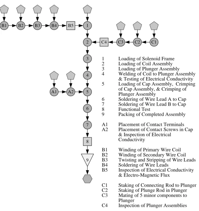
9: A Physical Flow Chart For The Production of An Automotive Ignition Coil 55 10: A Physical Flow Relationship Chart for a Formula One Racecar 59 11: A Physical Flow Block Layout Diagram For Krispy Kreme Doughnuts 61 12: Designing a Manufacturing System for an Automotive Starter Motor Solenoid Subassembly 65 Part IV: Developing An Improved Process Design Methodology
13: Shortcomings of the Traditional Process Design Methodology 81 14: Addressing the First Major Shortcoming: Ignoring the Flow of Information 82 15: Addressing the Second Major Shortcoming: The Overly Sequential Methodology 108 Part V: An Improved Process Design Methodology
16: Description 119
17: Benefits of the Improved Process Design Methodology 122
Part VI: Case Illustrations Where The Improved Design Methodology Was Used
18: An Informational Flow Chart For The Production of An Automotive Ignition Coil 125 19: A Informational Flow Relationship Chart for a Formula One Racecar 128 20: A Informational Block Layout Diagram for a Starter Motor Solenoid Subassembly 131 21: Designing a Manufacturing System for the DCS Pro 14n Digital Camera 132 Part VII: Conclusion
22: Closing Comments 169
Bibliography 171
Appendix A: Eastman Kodak Company Overview 177
Appendix B: Digital Camera Market Overview 183
Appendix C: DCS Pro 14n Digital Camera Overview 187
Part I
1: The Challenge To Be Solved
An estimated $500 billion is spent annually in the construction and modification of existing manufacturing facilities and over 8 percent of the US GNP has been spent on constructing new facilities each year since 1955.1 This incredible level of expenditure shows that the selection, location, and design of manufacturing systems are major strategic decisions for any firm.
By using efficient facilities planning techniques, these costs could be decreased by 10 to 30 percent.2 Indeed, much of the success of Japanese manufacturing companies can be attributed to their efficient design of production equipment and facilities. The challenge for firms then becomes: How to achieve efficient manufacturing facility design, maximizing production output, while minimizing resources required? To address this, firms have traditionally employed a standard design procedure that analyzes multiple aspects of a production system and then develops an efficient design that optimizes numerous performance parameters, such as overall cost, production output, and flexibility.
The development of facility layout principles has occurred since the design of steel factories and textile mills at beginning of the Industrial Revolution. The practice of factory design was formalized by designing assembly lines around the division of labor principles by Henry Ford and his contemporaries. Frederick Taylor’s work led to the creation of a dedicated scientific field: Industrial Engineering. Numerous other studies and practices were developed and used since then. In 1961, Muther published the Systematic Layout Planning (SLP) process, a design methodology that has become the foundation of American manufacturing system design.3
Since then, business literature has presented numerous techniques to design factory floor layouts. Many of the methods developed recently are based on the fundamentals of Lean Production, brought to the forefront of management focus after The MIT International Vehicle Program examined the Toyota Production System (TPS) and identified some of the elements that account for Toyota’s competitive advantages in manufacturing.4
Many factory design principles have now been incorporated into advanced computer software applications that assist in layout design. Modern computer applications can optimize a process layout based on minimizing quantitative or qualitative factors, such as total distance traveled by a part or the ease of material replenishment.
1 Production And Operations Analysis (4th Edition), Steven Nahmias, McGraw-Hill/Irwin, New York, New York, USA, 2001, Page 557.
2 Ibid.
3 Systematic Planning Of Industrial Activities (SPIF) – Volume I, Richard Muther and Lee Hales, Management & Industrial Research Publications, Kansas City, Missouri, USA, 1979.
4 The Machine That Changed the World: The Story of Lean Production, James P. Womack, Daniel Jones, Daniel Roos, HarperCollins Publishers, New York, New York, USA, 1991.
Early software applications promised that simply by defining a few process parameters, optimal process layouts could automatically be generated. Process engineers could therefore focus on other aspects of a process, rather than concerning themselves with optimizing the layout of the process. The layout of a factory would quickly become an automated task, which would thus fit nicely with the cultural movement towards automated production facilities. “During the 1980s, the predicted scenario was for a future populated with unmanned factories, which were to be highly automated and integrated both internally and externally.”5 Indeed, manufacturing was viewed as an afterthought; a task that could easily be accomplished, once the proper system had been implemented. “The lights-out factory of the future [captured] the imagination of almost everyone.”6
However, process engineers quickly realized that manufacturing could not be trivialized. The design of a process layout couldn’t simply be reduced to a system of linear equations. Simply, there are many aspects of facility design that cannot be represented in mathematical terms. For example, only a human can evaluate whether a process design will result in better communication and teamwork between operators. Only a skilled designer will be able to tell whether or not all of the important stakeholders are truly supportive of the proposed design. And no computer program will be able to demonstrate the process design’s strengths as it negotiates for project approval from senior management.
Therefore, even if a process architect does utilize one of the modern software utilities to design a process, the designer must still possess a thorough understanding of underlying design principles and methodologies that are involved in manufacturing process design.
In recent years, the dedication towards improving manufacturing has been reenergized. What was once considered an afterthought has now become a vital factor that determines the ultimate success of an organization. In fact, dramatic efficiency improvements in manufacturing processes must be achieved for a firm to compete in today’s global marketplace.
But many firms have a long way to go. For an average manufacturing firm, 95% of time that a physical part is on the factory floor is spent sitting idle, while 3.5% of the time is spent waiting for a
5 “Information Technologies For High-Performing Processes”, Cipriano Forza, Kathrin Tuerk, Osam Sato, High Performance Manufacturing: Global Perspectives, Roger G. Schroeder & Barbara B. Flynn (Editors), John Wiley & Sons, Inc., New York, 2001, Page 116.
6 “Simplification Before Automation”, Hal Mather, Integration and Management of Technology For Manufacturing, E.H. Robson, H.M. Ryan, and D. Wilcock (Editors), Peter Peregrinus, Ltd., London, England, United Kingdom, 1991, Page 5.
machine to be setup or torn down. That means a part is actually having value-added work performed only 1.5% of the total time!7
Much effort is therefore placed on improving individual manufacturing processes. However, even if the entire setup/teardown time is removed and the processing time for each operation is slashed, the bulk of the time that a part spends on the factory floor will remain untouched. Thus, the traditional focus on local process optimization will not lead to overall system optimization.8 Process architects need to recognize that “rather than each function attempting to optimize individually its operation, optimization of the overall enterprise must be the primary objective.”9 Therefore, in addition to focusing on improving the processes themselves, designers must place even greater emphasis on integrating the entire manufacturing system and transforming it into a seamless flow of parts and information.
“Recognizing that all participants in the enterprise…contribute to the success of the operation, the search for improved ways to create competitive products must affect them all. We can improve the competitiveness of U.S. manufacturing only when we have come to understand the factors that affect productivity of each of the segments of the manufacturing enterprise as well as the interaction among them. This search for new understanding implies a special need to improve the tools that are used to analyze and design systems of the complexity of a manufacturing enterprise.”10
Yet many firms still do not understand or feel the urgent need to transform their practices. Still others are aware of, but fail to implement the best practices of process design. In reality, many designs have never been adapted from the first day the equipment was placed on the production floor. Other designs have morphed over time from an efficient layout to a complex network of distinct operations. Even other processes still utilize process designs originally developed for a now obsolete product family.
There are many diverse reasons for this lack of optimal process design. One major reason is due to the lack of opportunities that exist for total process redesign since there is often a very small time period where a process can be designed or modified. Once a process has been put in place, the pressures of production dominate and prevent any improvements in the process design from being implemented.
7 Integrated Process Design and Development, Dan L. Shunk, Business One Irwin, Homewood, Illinois, USA 1992, Page 39.
8 “CIM Development: A Strategic Management Issue”, K.B. Chuah, Integration and Management of Technology For Manufacturing, E.H. Robson, H.M. Ryan, and D. Wilcock (Editors), Peter Peregrinus, Ltd., London, England, United Kingdom, 1991, Page 151.
9
“Designing An Information System For Integrated Manufacturing Systems”, Ulrich Flatau, Design And Analysis of Integrated Manufacturing Systems, Ulrich Flatau (Editor), National Academy Press, Washington, DC, 1988, Page 61.
10 Design and Analysis of Integrated Manufacturing Systems, W. Dale Compton (Editor), National Academy Press, Washington, DC, USA, 1988, Preface.
Unfortunately, the only opportunities to adjust a process design usually happen when a piece of machinery is being replaced, or a major equipment failure occurs. Even then, the brief window that exists only allows minor process improvements to be made.
“The nature of a growing business is such that with all the time pressures new equipment tends to get put in a spare corner rather than finding where the most logical place for it would be. And there it remains until years later when people get sick of the mess and inefficiency. The trouble is when it comes time to make the big move nobody is sure where the best spot is for all the machinery and equipment.”11
For that reason, process designers must take full advantage of the precious moments they receive to redesign a manufacturing process. The importance of the process’ physical design cannot be overstated.
“Without precise process designs…employees have little chance of consistently operating in ways that customers find convenient. They will have even less chance of successfully performing and coordinating the broader range of activities needed to deliver higher levels of value-added. As work gets more demanding and more complex, process becomes absolutely essential.”12
Therefore, when those windows for change open, it is critical that a process designer follow a systematic and structured procedure to developing a process design.
This thesis will present a review of the traditional process design methodology used to design a manufacturing production system. This methodology will be a synthesis of the SLP process developed by Muther and improvements that have been made to that process since its introduction.
Two major shortcomings of the traditional design process will be identified. The first limitation involves the neglecting of the importance of the flow of information when a physical production system is designed. The second is the overly sequential nature of the design process, which increases overall planning time and cost.
To address these shortcomings, specific concepts, models, and methods have been developed. These new techniques will focus upon the design of manufacturing information systems and the concurrent design of the physical and the informational design systems. When combined with the traditional design method, these new tools form the structure of an improved design methodology for
11 “How To Design The Best Layout For Your Factory”, Queensland Manufacturing Institute Ltd. Newsletter, September 2001, http://www.qmi.asn.au.
12 The Agenda: What Every Business Must Do To Dominate The Decade, Michael Hammer, Crown Business, New York, New York, USA, 2001, Page 57.
manufacturing processes. The end result will be a design methodology that will support the concurrent design of physical flow and informational flow manufacturing systems.
2: Key Findings of Project
The advancement of information technology in manufacturing requires process architects to refine their design procedures used to develop a new manufacturing system. No longer can these designers implement a physical production system first, and then later incorporate a capable information system to control that production system. Rather, they must design the physical production system and the information system in a concurrent fashion to ensure the resulting system yields a seamless flow of information as well as physical parts. Only by considering the sources, the needs, and the uses of information for each and every process element will the design team avoid creating the “Islands of Automation” that plague many over-complicated manufacturing systems.
This thesis presents concepts, models, and methods used to examine and design the flow of information through a production system. These methods are based upon existing practices that have traditionally been used to design manufacturing processes. The thesis presents that information flow can be represented as a flow of physical parts. Because of this, many of the same principles that apply to the design of physical flow production systems can be applied to the design of informational flow production systems.
This thesis provides case illustrations where the presented concepts, models, and methods were applied. These cases provide comprehensible and concrete illustrations of situations where these ideas have been successfully implemented.
The overall concepts presented are: 1) the flow of information is as important as the flow of product; 2) the flow of information is often more complicated than the flow of physical material, and frequently it is the sharing of information within a process that governs the process’ performance; 3) the flow of information can be modeled as the flow of physical parts, so many of the same principles that apply to the design of physical production systems can be applied to the design of information systems; and 4) the design of an information system must occur in a concurrent fashion with the development of the physical components of any manufacturing process.
3: Organization of Thesis
This thesis will begin by examining traditional methods used in manufacturing process design. Some traditional flow models and techniques used to determine material flow, machine placement, and operation sequencing will be presented and critiqued. In addition, some applications of these methods will be given that demonstrate how these methods were effectively implemented.
Next, the shortcomings of traditional methods will be critiqued. The thesis will show that the nature of manufacturing has dramatically changed, mainly due to the advancements made in information technology. This improved technology has opened the door to a world where information (and its effective utilization) can be harnessed to become a sustainable competitive advantage.
A discussion of the pitfalls of not considering the information system’s design at the outset of a manufacturing process design exercise will follow. The thesis will show how overall costs, system complexity, user frustration, and process rigidity were all unnecessarily increased by not considering the information system design when first designing the process.
Next, this thesis will demonstrate the need for concurrent design of manufacturing process and information systems. After reviewing the background of the rapid evolution of information technology and manufacturing process command and control software, this thesis will show how the “Power of Information” can revolutionize modern day manufacturing processes in terms of quality, cost, throughput, and resource optimization.
In the section following, it will be shown that the generation, manipulation, transportation, dissemination, and consumption of information can be modeled and treated in an almost identical manner as the flow of physical material. Once this has been demonstrated, traditional techniques used to model the physical production system will be adapted to the information system. This model’s application in multiple settings will then be presented, showing the flexibility of the modeling technique.
Next, this thesis will present a framework for the concurrent design of a physical manufacturing system and an information manufacturing system. This framework will be based upon foundational design principles of both information system design and physical production design, yet will include techniques that bridge the pitfalls earlier identified that result from isolated design activities.
Once these frameworks, models, and techniques have been identified, a case illustration will be presented where the improved method was applied. This case, detailing the development of the manufacturing system for a new digital camera, provides comprehensible and concrete illustrations of a situation where these ideas have been successfully implemented.
Thus, the models, techniques, and frameworks presented in this thesis will result in a concrete package that can be used to concurrently design a physical manufacturing system and an information manufacturing system.
4: Literature Review
The thesis has drawn upon a number of research materials from recognized subject matter experts. While an effort was made to include significant detail in this project, the interested reader should refer to the following sources to develop a greater understanding.
The literature used in this project can be categorized into five major areas: facility layout design, lean production, process reengineering, information systems, and concurrent engineering. In addition, several other reference sources on general manufacturing engineering were reviewed.
Facility Layout Design
Facility Layout and process design can be traced back to the Industrial Revolution, where the designs of early processes were optimized. The practice of layout design was formalized by Muther (42), refined by Francis and White (22), and soon became part of standard Industrial Engineering materials, such as Maynard’s handbook (40) and other foundational materials used to train process engineers (43). Lean Production
Numerous texts and journal articles about the Toyota Production System and Lean Production have been published. Specifically, this thesis reviewed materials recognized as the fundamental sources of Lean Production thinking. These include Ohno’s work on the Toyota Production System (47), Womack’s texts on Lean Manufacturing (58, 59), Dertouzos’, Lester’s, and Solow’s text (11), as well as Goldratt’s material (24).
Process Reengineering
Much of the material pertaining to process simplification, streamlining and redesign was drawn from Hammer’s work on process reengineering. Recognized as one of the originators of the modern process reengineering movement, Hammer’s materials (28), (29), and (30) provide background on the need for process reengineering, present a procedure for reengineering, and describes numerous cases which show the profound benefits that process reengineering can bring.
Information Systems
Tremendous volumes of material on the design and use of information systems in a manufacturing setting have been published. The depth of material in this field demonstrates how quickly this area is expanding and advancing. Rather than selecting materials tied to one direct technology, this thesis focused on references that describe the overall issues at hand, and general architectures that are used to develop an efficient system. Such materials include texts by Satori (52) and Chorafas (5).
In addition, proceedings from numerous technical symposiums were reviewed, which gave the overall state of the industry. These proceedings included those by Brown, Mas, and Hlodversson (2), Compton (8), Flatau (20), Goossenaerts, Kimura, and Hans Wortmann (25), Goossenaerts (26), Lastra, Encarnação, and Requicha (36), Robson, Ryan, and Wilcock (50), and Rix and Schlechtendahl (51).
While much of the technology described in the above materials is now obsolete, the underlying principles and considerations contained within (especially pertaining to system architecture design) are still very much applicable.
Concurrent Engineering
Concurrent Engineering originated with the material published by Nevins and Whitney (44) and enhanced by Hartley (32). Since then, Concurrent Engineering has evolved into other forms such as Integrated Product and Process Development, as described by Shunk (57). In addition, Fine (19) expands Concurrent Engineering to examine how its can be used in the design of supply chains as well as products and processes. Because of the benefits that Concurrent Engineering provides, its use has been incorporated into standard product design processes, such as that used by Eppinger (18) and Compton (8).
Part II
In any given manufacturing firm, at any given time, there is likely a production process being designed. In fact, due to the rapidly shortening of most products’ lifecycles, it could be stated that all processes are always in a state of design. Process teams are continually acting to implement improvements to the production system, launch the next product, or introduce of the next iteration of advanced process technology. The list of reasons to change a process’ design is long, and includes such diverse motives as: 13
• A change in the design of a product
• The addition or deletion of a product from a company’s product line
• A significant increase or decrease in the demand for a product
• A change in the manufacturing methods used to produce a product
• The replacement of one or more pieces of process equipment
• The adoption of new safety standards
• A change in the organizational alignment of a company
• A decision to build or expand a production facility
• A need to alleviate crowded working conditions
• The desire to improve the housekeeping or appearance of a production area
• A change in the storage space required for a product
• A change to the flow of material through a process
• The need to overcome gradual changes in the existing process that have appeared over time (bottlenecks, delays, idle time, backtracking, failure to meet schedules, high ratio of handling time to production time, etc.)
Often the exact purpose, scale, scope, and timeframe involved with a particular design effort are different from all other projects ever undertaken by a firm. Indeed, in the vast majority of cases, the process design projects are completely unique. Therefore, each project brings new challenges.14
Due to the lack of similarity between process design projects, some may assume that it is impossible to develop an overall design method applicable to each and every situation. And, even if a formal design approach did exist, it would likely be so generic and abstract that it would be of little tangible use to a process design team.
However, a design method has indeed been developed and has been successfully applied to thousands of process design projects.15 This design approach allows any process architect to follow a structured, clear, and straightforward path through the steps required to develop an efficient process design that meets all requirements. This method assists the process design team, allowing it to take advantage of a logical progression of design steps that will ultimately lead towards the team’s goal.
13
Facility Layout and Location: An Analytical Approach, Richard L. Francis and John A. White, Prentice-Hall, Inc., Englewood Cliffs, New Jersey, USA, 1974, Page 32.
14 Systematic Planning Of Industrial Activities (SPIF) – Volume I, Richard Muther and Lee Hales, Management & Industrial Research Publications, Kansas City, Missouri, USA, 1979, Page 7-5.
15 Ibid.
In this section, this design technique will be reviewed in detail. In addition, several key process steps that are not included in the original methodology will be discussed. These additional steps have developed over time, and when combined with the original approach, they create a thorough process design methodology that meets the needs of process architects.
5: The Systematic Layout Planning (SLP) Design Process
The Systematic Layout Planning (SLP)16 Design Process, originally developed by Richard Muther in 1965, is commonly used as the foundation of all manufacturing process design methods. This multi-step process repeatedly demonstrates its applicability to a wide number of process design projects, whether they are the design of a fully automated production facility, or the design of a flexible manufacturing job shop facility. This “organized, universally applicable approach”17 is equally applied to process design projects in newly constructed facilities, or process redesign efforts in well-established facilities, and can be applied in the same way to minor as to major process design efforts.
The key objectives for the Systematic Layout Planning process include designing and determining the basic flow patterns of parts and material through the process, the identification of the size of each process element and the relationships each element shares with others in the process. In addition, SLP seeks to specify both the conceptual and the detailed design aspects of the configuration, orientation, and placement of each piece of process machinery, equipment, and support infrastructure.
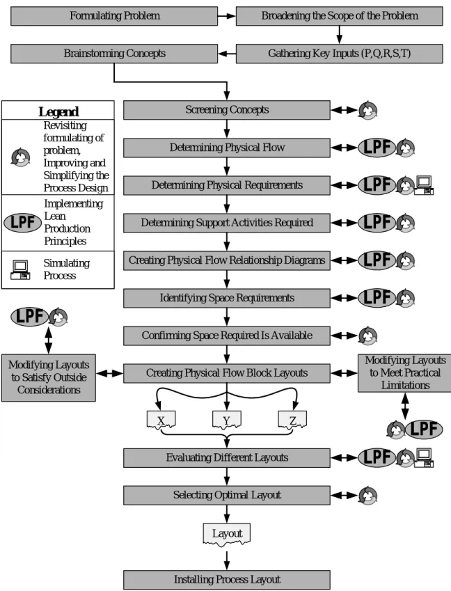
To accomplish these objectives, the SLP process consists of 13 major elements, arranged in a largely sequential manner. A graphical representation of the design methodology is shown in Figure 1. Each step in the SLP process will be briefly described to show how the process is applied to a project.
Step 1: Gathering Key Inputs (P, Q, R, S, and T)
The first fundamental process step consists of the gathering of key process inputs, conveniently grouped into 5 alphabetical designations (P, Q, R, S, and T).
Gathering the “P” inputs involves identifying those Products that will be manufactured using the process under design. The list of products identified includes current and future versions of those products, as well as all forms that are similar and might use the same manufacturing processes. These product families “will have variations from product to product such as different model configurations but
16 Facility Layout and Location: An Analytical Approach, Richard L. Francis and John A. White, Prentice-Hall, Inc., Englewood Cliffs, New Jersey, USA, 1974, Page 35.
17 Systematic Planning Of Industrial Activities (SPIF) – Volume I, Richard Muther and Lee Hales, Management & Industrial Research Publications, Kansas City, Missouri, USA, 1979, Page 7-1.
they generally have the same base model.”18 In addition, the team identifies other product inputs (raw materials, components, and subassemblies) that are required in producing the identified products.
X Y Z
Installing Process Layout Selecting Optimal Layout Identifying Space Requirements
Confirming Space Required Is Available
Creating Physical Flow Block Layouts Modifying Layouts to Satisfy Outside Considerations Modifying Layouts to Meet Practical Limitations
Evaluating Different Layouts
Layout
Gathering Key Inputs (P,Q,R,S,T)
Determining Physical Flow
Determining Physical Requirements
Determining Support Activities Required
Creating Physical Flow Relationship Diagrams
Figure 1: The Systematic Layout Planning (SLP) Process19
18 “How To Design The Best Layout For Your Factory”, Queensland Manufacturing Institute Ltd. Newsletter, September 2001, http://www.qmi.asn.au.
19 Systematic Planning Of Industrial Activities (SPIF) – Volume I, Richard Muther and Lee Hales, Management & Industrial Research Publications, Kansas City, Missouri, USA, 1979, Page 7-3.
Gathering the “Q” inputs consists of predicting the Quantity of parts that will be produced with the process, including the breakdown of each product variation that could be produced. The design team bases quantity levels by considering current demand level as well as demand forecasts. The design team also identifies the magnitude of uncertainty that is associated with each volume production.
Gathering the “R” inputs involves specifying how the materials will be Routed through the process, in terms of which process operations are required to make the product. Designers discover what the sequence of operations must be, and which equipment must be involved in production.
Next, identifying the “S” inputs consists of specifying the Staffing services required to assist in the production of the product, including equipment operators and supervisors.
Finally, gathering the “T” inputs consists of identifying Time considerations, such as required cycle times, shipment and delivery frequencies, as well as external seasonality issues that may affect production.
For all key inputs, the design team clearly states the desired levels of performance. If available, the team also determines the current levels of performance for those key aspects so objective metrics can be set that will allow specific monitoring of the improvements made to the process.
By completely gathering the key inputs, as well as establishing metrics for important performance characteristics, the process design team gathers most of the information that will be required in the subsequent steps of the SLP process.
Step 2: Determining Physical Flow
The team continues by reviewing the physical flow of materials through the process. This step involves documenting the amount of each product type that must flow over a process route. In step 1, the team discovered many details about the product, including which components and raw materials are used to create the product, as well as what processes are required to manufacture each component of the final product. Using this knowledge, the design team can decompose the final product and can determine the necessary sequence of operations needed in the manufacturing system.
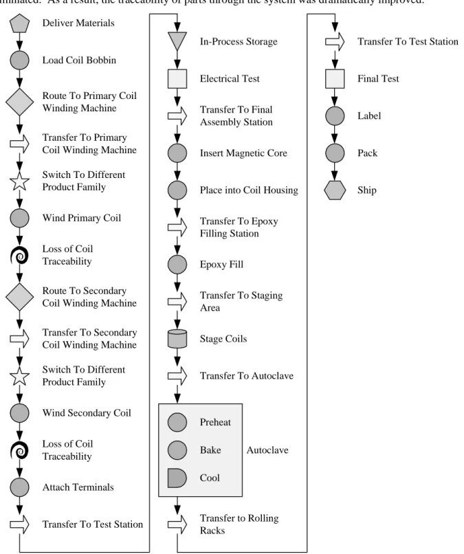
Once the sequence of operations is determined, and the required process steps are known, the design team constructs the Physical Flow Chart, the first of three key foundational elements used in manufacturing system design. While the Physical Flow Chart will be described in detail later in this thesis, the Chart can be briefly described as a high-level “graphical representation of the sequence of all operations, transportations, inspections, delays, and storages occurring during a process or procedure. It
includes information considered desirable for analysis, such as time required and distance moved.”20 In addition, the Chart shows “the points at which materials are introduced into the process, and of the sequence of inspections and all operations except those involved in material handling.”21 Constructing the Physical Flow Chart allows the design team to comprehend all of the steps and the sequence of those steps required to transform raw materials into end products.
Often, there are different sequences of operations that can be developed that will allow for the production of the end product. In addition, there are different process technologies and types of process equipment that can be used to create the desired product attributes. The design team evaluates each of these sequences and technologies and selects only those sequences that are feasible. These different sequences will then be rigorously evaluated and compared at later stages in the process.
Once the physical elements required to manufacture the desired product are identified, the team now investigates the physical requirements that will be required to meet production demands.
Step 3: Determining Physical Requirements
In this step, designers take the required volume demands, as well as the production capacities of the pieces of specified equipment and determine the number of each process element that will be needed to meet the required volumes.22 The team then uses the number of required pieces of production equipment to estimate the number of operators and support staff that will be required.
In completing this step in the design process, the team obtains a detailed listing of the numbers of each type of process equipment needed, as well as the number of equipment operators needed.
Step 4: Determining Support Activities Required
The team then proceeds to the fourth step of the SLP process, which involves the identification of external supporting activities (such as maintenance, material handling, logistics, labor relations, housekeeping, and quality control) that will interact and assist the process. The design team must identify these external activities at this point, since it is vital that all parties that have a stake in the ultimate configuration of the manufacturing process are considered early and throughout its design.
Step 5: Creating Physical Flow Relationship Charts
20 Industrial Engineering Handbook, 2nd Edition. H.B. Maynard, McGraw Hill Book Company, Inc., New York, 1963, Page 2-25.
21 Ibid, Page 2-21.
22 In addition, the team should identify the uncertainty in each forecast. This will permit the team to ensure that the process is capable of meeting larger-than-expected production levels, should they occur, while at the same time ensure that the guaranteed excess capacity is not unreasonably high. While it may be simpler for the team to base the design of the new process on current production levels, the design team should ensure that they still consider the future production levels for the current product, as well as the production volume for product versions that may be may down the road.
The design team proceeds with the next step of the SLP process, which involves the creation of the Physical Flow Relationship Chart, the second of three key foundational elements in manufacturing system design.
The Physical Flow Relationship Chart (described in more detail later in this thesis) allows the design team to recognize the underlying relationships between different process elements and is “a graphical means of representing the desirability of locating pairs of operations near each other.”23 By understanding and categorizing these relationships, the design team can identify the optimally sequenced process flow, locate process elements close together that need to be linked, and separate those process elements that need to be kept apart.
Step 6: Identifying Physical Space Requirements
This step involves the analysis of space requirements needed by the process being designed. Drawing on the list of necessary pieces of equipment and operators needed to staff that equipment, the design team calculates the amount of overall floor space that will be required by the process equipment, the operators, and the space that will be needed for other areas such as material storage, maintenance access, and areas for work team meetings, and break areas.
In determining these space requirements, the team considers the possibility of future expansion and change. The layout must be flexible enough to accommodate changes in product, process, and schedule design.24 By ensuring that the layout is flexible, the need to make major changes in the future decreases. Therefore, the design team often intentionally overestimates the required physical area, in order to ensure there is adequate room for future expansion.
Step 7: Confirming Space Required Is Available
Once the space requirements have been calculated, the design team compares this amount to the space that has been allocated in the production facility. For a given process, if more space is required than is available, the design team searches for a new location in which to place the process. If no new locations can be found (and the space required by that process cannot be reduced), the design team must abandon the current design concept and investigate whether another process design will fit,
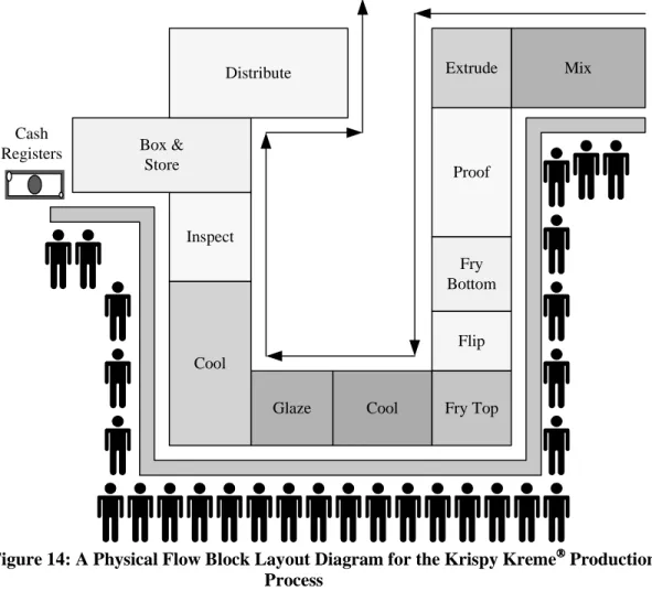
Step 8: Creating Physical Flow Block Layout Diagrams
In this step, designers develop Physical Flow Block Layout Diagrams, the third key foundational element in manufacturing system design. In these Diagrams (that will be described in more
23 Production And Operations Analysis (4th Edition), Steven Nahmias, McGraw-Hill/Irwin, New York, New York, USA, 2001, Page 560.
24 Facility Layout and Location: An Analytical Approach, Richard L. Francis and John A. White, Prentice-Hall, Inc., Englewood Cliffs, New Jersey, USA, 1974, Page 71.
detail later in this thesis), the process equipment is laid out conceptually in the allocated floor space. Multiple configurations and orientations of each process are generated for further analysis. Each Diagram allows the design team to graphically visualize different process design concepts, review material and part flows, and identify how and external areas will be affected by a specific design.
Step 9: Modifying Layouts To Satisfy Outside Considerations
The team now modifies the proposed designs to account for a variety of considerations. For example, one issue could be the need to access a certain location on a specific piece of equipment for maintenance purposes. Another consideration could be the need to separate different process elements due to the limited supply of utilities in a given area. Or, the presence of building constraints (such as support columns) that were not previously identified could require the modification of a process layout. This step is highly iterative, as the concepts are continually updated to reflect changes required by new considerations.
Step 10: Modifying Layouts To Meet Practical Limitations
This step, also highly iterative, modifies the process layouts to account for any practical limitations. The design team considers the many impacts that each proposed plan will have on the overall system. These impacts can range from the high cost of moving a specific piece of equipment, to the need for larger aisles to account for the changing of tooling, to the requirement for fewer operators per square foot in order to satisfy safety regulations. In addition, this step should consider the impacts to other areas of the firm, such as the need to shut off electricity during process installation.
Steps 8, 9, and 10 are all iterative, and during these cycles, each process layout is repeatedly modified to ensure all factors have been accounted for.
Step 11: Evaluating Different Layouts
The design team now has one or more process layouts that have been significantly modified from their initial design concepts. In this process step, the design team briefly revisits the conclusions made at each prior step. The team ensures that any modifications made to the process design during the later stages of the process have not violated any earlier design constraints. The team also recalculates the space requirements of the process to ensure that the design can still be placed in the allocated area.
Step 12: Selecting the Optimal Layout
In this step, the different layouts are compared and judged against specified criteria to identify which design best meets the requirements. To accomplish this, the design team first develops criteria on
which to judge the attractiveness of each design. Then, using concept scoring25, the design team assigns weights to various evaluation criteria, according to those factors that are the most important. Such factors can include (but are not limited to) those shown in Table 1.
• Ease of future expansion
• Effectiveness of material-handling
• Utilization of process equipment
• Ease of supervision and control
• Investment or capital required
• Flexibility of layout
• Utilization of overall floor space
• Fit with company organization structure
• Meeting of future capacity requirements
• Savings, payout, return, profitability Table 1: Potential Factors For Use In Concept Scoring
Each design is scored on a numerical scale on how well it meets the criteria, relative to the other c concepts. These ratings are then multiplied by the weights and summed to achieve an overall utility for the design. The design team either selects the concept with the highest rating, or investigates whether two or more designs that each scored well can be combined to achieve one that is even superior.26
Step 13: Installing Process Layout
Having selected a process design that meets all requirements and does not violate any design constraints, the team then moves to implement the design. The design team has at this point completed its mission and can be confident that the installed process will yield substantial improvements over the previous process.
Summary of the SLP Process
At the conclusion of the Systematic Layout Planning process, the design team will have accomplished a number of objectives. First, the stated goals of the SLP process (1. the design and determination of the basic flow pattern of parts and material through the process; 2. the identification of the size of each process element and the relationships each element shares with others in the process; and 3. the configuration, orientation, and placement of each piece of process machinery, equipment, and support infrastructure) will all have been achieved. In addition, by considering the needs of multiple stakeholders in the design process, from the initial stage of gathering key process inputs through the final evaluation of a layout design, the selected design will garner the support of all necessary parties, and all constituents will have cooperated to obtain the solution. Finally, by creating the Physical Flow Chart, the Physical Flow Relationship Chart, and the Physical Flow Block Layout Diagram, the path taken to develop the design will have become carefully documented and can assist in further process improvement efforts.
25 Industrial Engineering Handbook, 2nd Edition. H.B. Maynard, McGraw Hill Book Company, Inc., New York, 1963, Pages 8.36-8.65
26 Facility Layout and Location: An Analytical Approach, Richard L. Francis and John A. White, Prentice-Hall, Inc., Englewood Cliffs, New Jersey, USA, 1974, Pages 12-14.
In summary, the SLP Process provides a process design team with a robust design methodology that is extremely flexible to multiple situations. The SLP process provides “a framework, a pattern, and a set of conventions which can be used on any layout-planning project without imposing constraints or restrictions on the handling of data or on the individual requirements of each discrete layout project.”27 Its plain logic and straightforward manner, combined with its simplicity and highly segmented sequence, continue to make the Systematic Layout Planning process the primary design methodology used by manufacturing process architects.
6: Adding More to the SLP Process
While the SLP process is extremely flexible and can be adapted to numerous situations and process design projects, its formal definition does not include several significant activities that are actually performed in several design exercises. By formally expanding the SLP process to include these vital process steps, a comprehensive design methodology can be developed that better describes all of the crucial steps that are traditionally involved in most manufacturing process design projects.
Additional Step 1: Formulating the Problem
In many complicated manufacturing systems, it is often difficult to locate the true cause of the observable symptoms. This is especially valid for production systems, because the overall performance of the system is dependent upon hundreds of factors, usually including the complex interactions of several of those factors.
Because of this complexity, many process design projects, especially process redesigns, do not yield dramatic performance gains. A reason for this is the failure of the designers to properly formulate the key problem facing the team.28 Teams become biased by only considering the current elements, flow, and products involved with the existing process design. As a result, thinking remains bound to the existing process, therefore the team only discovers and implements incremental improvements. 29
To overcome this, the initial framing and clarifying of the issue at hand must be the first major step of any systematic problem solving method. The problem solving team must examine each observable symptom and, through a series of investigative and diagnostic processes, determine the underlying root cause of those symptoms. The team must focus on the “outcome of work, rather than on work as an end it itself…[and must] see itself and its work from the perspective of the customer, rather
27
Systematic Planning Of Industrial Activities (SPIF) – Volume I, Richard Muther and Lee Hales, Management & Industrial Research Publications, Kansas City, Missouri, USA, 1979, Page 7-5.
28 Facility Layout and Location: An Analytical Approach, Richard L. Francis and John A. White, Prentice-Hall, Inc., Englewood Cliffs, New Jersey, USA, 1974, Pages 10-11.
29
than from its own.”30 The true cause is then formulated as a problem statement challenge, and the team then forms and develops a series of solution concepts that address and attack this problem.
Once this problem has been properly formulated, the team has a much higher probability of solving the true issue. However, if the problem formulation step is not performed, the team often spends significant time and effort treating the apparent symptoms, rather than correcting the actual cause and preventing recurrence.
As more information is gathered at each step in the design process, the team should revise the current problem formulation, thereby ensuring that the solutions being developed are addressing the true issue, not just treating deficiencies in the current design. In this manner, the team should eventually locate the underlying problem in the system, even though the path taken to find that cause was not direct.
While the repeated examination of the underlying problem may appear to lengthen the design process, these iterations make certain that the solution ultimately developed and implemented by the team will result in process design improvements that will benefit the entire production system, rather than overcome minor symptoms.
Additional Step 2: Broadening the Scope of the Problem
In designing a process, more substantial performance gains can be achieved if the team consciously broadens the scope of the problem statement facing the team. This requires the team to take a “black box” design approach to specify the issue at hand. Using this approach, the team ignores the current design of the process, and only considers the problem as the need to turn a given set of inputs into a required set of outputs. The exact process elements remain unknown and unspecified during this problem formulation stage. The team carefully details the characteristics of the problem, while ensuring that any possible approaches to solve the issue are framed as broadly as possible.31 Any existing biases and assumptions regarding the product, or process, are actively challenged, so the team may discover the key requirements of the problem. The design team delays any charts, diagrams, or layouts until later stages, and instead focuses on the formulation and the analysis of the problem. This frees the design team from the “tired ideas, irrelevant methods, and obsolete systems”32 that have been used in the past and enables the team (during the later layout design stages) to explore as many possibilities as time constraints and organizational boundaries permit.
30 The Agenda: What Every Business Must Do To Dominate The Decade, Michael Hammer, Crown Business, New York, New York, USA, 2001, Page 62.
31 Facility Layout and Location: An Analytical Approach, Richard L. Francis and John A. White, Prentice-Hall, Inc., Englewood Cliffs, New Jersey, USA, 1974, Pages 11-12.
32 The Agenda: What Every Business Must Do To Dominate The Decade, Michael Hammer, Crown Business, New York, New York, USA, 2001, Page 52.
For example, rather than specifying the design problem as the “need to locate lathe XYZ somewhere between end mill ABC and welding station DEF”, the team should identify the underlying issue as the “need to satisfy a given customer’s order for a specific project.” The reason for this is that the design of the product to be produced may have changed so much from the current version that a lathe, an end mill and a welding station may not be the best process elements to use to make the product. Expanding the scope permits the team to select a concept from an expanded possible solution space, increasing the chances of finding a solution that achieves the desired improvement levels.
The broadening of the problem scope has become a vital part of the manufacturing system design process. As process designs become more advanced and complex, there must be increased dedication towards maintaining a clearly articulated problem statement yet ensure the team if free to consider fresh approaches to the problem.
Additional Step 3: Brainstorming Concepts
Once the problem has been formulated in a broader manner, the number of possible design concepts increases dramatically.33 Designers are now freed from only considering incremental improvements to the current process, and can explore creative solutions to the underlying problem.
Therefore, by actively brainstorming to identify concepts that can solve the broad formulated problem, the design team is much more likely to discover a dramatic concept, that elegantly solves the required problem in a novel, yet simple manner.
Additional Step 4: Screening Design Concepts
Following the brainstorming exercise, the design team typically needs to perform an initial screening of process concepts. During the brainstorming step, the design team identified a large number of concepts, likely including many concepts that take an unconventional approach to the problem. As a result, it is likely that the several of the concepts will not be feasible at the current time.
Using a pre-specified evaluation method, the team reduces the number of concepts to a small number of promising concepts. However, in screening these concepts, the design team resists the temptation to select only those concepts that resemble the current process. To achieve dramatic results, the team is seeking concepts that will simplify the overall process, even if they are completely different from the existing process.
Additional Step 5: Improving and Simplifying the Process Design
Once the flow of materials and the support activities for the process have been identified, the design team reviews each of these areas to identify further areas for process improvement and
33
simplification. The team looks for opportunities to eliminate unnecessary steps, streamline necessary operations, and to reorder the sequence of workflow to reduce processing time or effort. It is vital to conduct this review at this stage, rather than after the layout has been optimized, because “you don’t want to invest in an optimized layout of a sub-optimal process. That is akin to automating a process that is altogether unnecessary.”34 By improving the design concepts at this early stage, designers ensure that any inefficient practices that plague the existing concepts do not continue forward and become solidified during later stages of the process.
Although the improvement and simplification tasks are first performed at this stage, they are actually performed at each subsequent stage of the design process. This is to address the added complexity that arises as different relationships are discovered and as the process layout is determined. Through repeatedly simplifying and improving the concept, much of the unneeded complexity can be removed. It is only through these activities that the team ensures the ultimate complexity of the production system will be minimized, enabling better production performance.
In essence, the step of improving and simplifying a process design involves the core activities of process reengineering. Process reengineering is “the fundamental rethinking and radical redesign of business processes to achieve dramatic improvements in critical, contemporary measures of performance, such as cost, quality, service, and speed.”35 “It ignores what is and concentrates on what should be.”36 Overall, it tosses away an existing work design and reinvents processes that are better suited to the current business environment. Process reengineering experts emphasize that firms must examine all of their business processes, and ask the following vital questions: 37, 38
• What does this process step do?
• What is this process step’s purpose?
• How does this process step create value for customers?
• Is this process step even necessary?
• Has the simplification exercise been conducted to such an extent that a value-added process has truly been identified?
• Is the flow through this process step streamlined?
• Is the automated system justified?
• Is this process step simplified so automation can be achieved at its simplest level?
34 “How To Design The Best Layout For Your Factory”, Queensland Manufacturing Institute Ltd. Newsletter, September 2001, http://www.qmi.asn.au.
35 Reengineering The Corporation: A Manifesto For Business Revolution, Michael Hammer and James Champy, HarperCollins Publishers, Inc., New York, New York, USA, 1994, Page 33.
36
Ibid, Page 33.
37 Integrated Process Design and Development, Dan L. Shunk, Business One Irwin, Homewood, Illinois, USA 1992, Page 64.
38 The Agenda: What Every Business Must Do To Dominate The Decade, Michael Hammer, Crown Business, New York, New York, USA, 2001, Page 64.
• What measures are used to judge the performance of this process step?
• What are the current levels of those measures?
• What other process steps interface with this one?
• What do other process steps need from this one, and what does this process step need from others?
If the answers to these questions cannot be quickly and simply expressed, the process design team should keep pushing to simplify and streamline the process design. The team should look for opportunities to consolidate neighboring process steps, or eliminate process steps altogether, while still maintaining or improving the overall simplicity of the process. Often, process elements persist in a process long after the need for them has disappeared. Product, technological, or staffing changes all contribute to make some process elements obsolete, even though they have never been removed from the official process flow. Therefore, just by asking the simple questions, and then driving to the root foundation of underlying assumptions, the design team can frequently find valuable potential for improvement.
In many cases, after each process step has been examined using the above guidelines, dramatic savings will be achieved. Indeed, reengineering advocates express that most savings come from process simplification rather than process automation.39 Actually, after simplifying operations, it is often found that so much improvement has already been made, that automation of the resulting step is not needed. 40
Therefore, as process designs become more advanced, there must be increased dedication towards improving and simplifying each and every aspect of a process design. Each proposed concept must be repeatedly reviewed and adapted to make certain it is a logical design that does not introduce unnecessary complexity into the overall production system.
Additional Step 6: Implementing Lean Production Principles
One of the most major influences on modern production system design is the Toyota Production System developed by Taiichi Ohno. The Toyota Production System showed how the world could manufacture products more efficiently and with better quality, but would require fewer resources and lower overall costs. In addition, the Toyota Production System took an important look at how people are treated in a factory setting and showed how they can be effectively empowered to yield incredible performance improvements.41 The Toyota Production System showed how to “do more and more with
39
Integrated Process Design and Development, Dan L. Shunk, Business One Irwin, Homewood, Illinois, USA 1992, Page 69.
40 Ibid, Page 64.
41 Toyota Production System: Beyond Large Scale Production, Taiichi Ohno, Productivity Press, Portland Oregon, USA, 1988, Foreword.
less and less – less human effort, less equipment, less time, and less space – while coming closer and closer to providing customers with exactly what they want.”42
After years of lagging behind their Japanese competitors, Western manufacturers started to examine the competitive advantage that the Toyota Production System gives. This examination allowed firms to identify the central elements of the Toyota Production System, which would in turn allowed them to redesign their own processes and close the competitive gap.
Labeled as “Lean Production” by Womack (et al), the incorporation of the Toyota Production System’s manufacturing fundamentals resulted in numerous benefits.43 In many successful implementations of lean manufacturing, labor productivity typically doubles all the way through the system. In addition, production throughput times and inventory levels are slashed by 90 percent. Errors reaching the customer are typically cut in half, as are job-related injuries. Also, time-to-market for new products is cut in half, allowing a wider variety of products to be offered to customers at very modest additional cost. In addition, capital investment and physical resources required are greatly reduced.44 After initially designing a manufacturing process using lean production fundamentals, firms can continue to reap additional benefits through the use of continuous improvement activities. These improvements, “can typically double productivity again through incremental improvements within two to three years and halve again inventories, errors, and lead times during this period.”45
While there are numerous sources detailing the Toyota Production System and Lean Production Fundamentals, a detailed analysis of Lean Production will not be presented here. Interested readers should refer to Ohno46, Womack47, and Womack48.
Simply, the Toyota Production System focuses upon the consistent and thorough elimination of all sources of waste. Waste can be described as any human activity that absorbs resources but creates no value. The key categories of waste include: 49
• Overproduction (Production of items no one wants so that inventories and remaindered goods pile up)
42 Lean Thinking: Banish Waster and Create Wealth In Your Corporation, James P. Womack and Daniel T. Jones, Simon & Schuster Publishers, New York, New York, USA, 1996, Page 15.
43 Ibid, Page 15. 44 Ibid, Page 27. 45 Ibid, Page 27.
46 Toyota Production System: Beyond Large Scale Production, Taiichi Ohno, Productivity Press, Portland Oregon, USA, 1988.
47
The Machine That Changed the World: The Story of Lean Production, James P. Womack, Daniel Jones, Daniel Roos, HarperCollins Publishers, New York, New York, USA, 1991.
48 Lean Thinking: Banish Waster and Create Wealth In Your Corporation, James P. Womack and Daniel T. Jones, Simon & Schuster Publishers, New York, New York, USA, 1996.
49