Publisher’s version / Version de l'éditeur:
Vous avez des questions? Nous pouvons vous aider. Pour communiquer directement avec un auteur, consultez la
première page de la revue dans laquelle son article a été publié afin de trouver ses coordonnées. Si vous n’arrivez pas à les repérer, communiquez avec nous à [email protected].
Questions? Contact the NRC Publications Archive team at
[email protected]. If you wish to email the authors directly, please see the first page of the publication for their contact information.
https://publications-cnrc.canada.ca/fra/droits
L’accès à ce site Web et l’utilisation de son contenu sont assujettis aux conditions présentées dans le site LISEZ CES CONDITIONS ATTENTIVEMENT AVANT D’UTILISER CE SITE WEB.
Canadian Building Digest, 1967-10
READ THESE TERMS AND CONDITIONS CAREFULLY BEFORE USING THIS WEBSITE.
https://nrc-publications.canada.ca/eng/copyright
NRC Publications Archive Record / Notice des Archives des publications du CNRC :
https://nrc-publications.canada.ca/eng/view/object/?id=dc1f8498-a671-401e-b4eb-00acd83ea078
https://publications-cnrc.canada.ca/fra/voir/objet/?id=dc1f8498-a671-401e-b4eb-00acd83ea078
NRC Publications Archive
Archives des publications du CNRC
For the publisher’s version, please access the DOI link below./ Pour consulter la version de l’éditeur, utilisez le lien DOI ci-dessous.
https://doi.org/10.4224/40000776
Access and use of this website and the material on it are subject to the Terms and Conditions set forth at
Precast concrete walls: a new basis for design
Canadian Building Digest
Division of Building Research, National Research Council Canada
CBD 94
Precast Concrete Walls – A New
Basis for Design
Originally published October 1967. J.K. LattaPlease note
This publication is a part of a discontinued series and is archived here as an historical reference. Readers should consult design and regulatory experts for guidance on the applicability of the information to current construction practice.
A new approach is required for the design of walls incorporating precast concrete panels. Conventional design calls upon the precast panel to form the external facade and the rain and airtight barrier. The panel also supports the other components of the wall and carries wind loads, but in most cases it does not form part of the structural system of the building. In trying to fulfil these various functions, conventional design encounters problems that are inherent in the basic concept. Some can be overcome by an exceptionally high standard of detailing and workmanship, but the prudent designer will call for only a normal standard of skill. A new basis for design, based on sound scientific principles that make abnormal skills unnecessary avoids the problems by eliminating their causes.
What Is Required of a Wall?
It was shown inCBD 93that many troubles stem from a failure to control temperature and water, which can enter a wall from two principal sources - water vapour inside, and rain and snow outside the building.
1. The chief mechanism carrying water vapour into the wall is air movement. This movement may take place through the wall or it may be a convective movement into cold spaces in the wall that returns to the inside of the building. Since with conventional methods of construction it is not reasonable to expect to eliminate all spaces within the wall, it is necessary to separate these spaces from the air within the building. In so doing, through-wall air leakage will also be stopped. Thus, one requirement of the wall is an air barrier on the warm side of the insulation. 2. To prevent rain penetration, it is necessary either to have a completely impervious outer skin
over the whole surface of the wall or to control the forces that can move the water from the face into the wall. It is possible to make individual parts of the outer skin impervious, but again it is not realistic to expect that this can be achieved over the entire surface. Thus at any line of potential leakage, such as a joint between panels, it is necessary to control the forces. This can
be done most readily by providing an air chamber behind the wetted face and ensuring that the air pressure in this chamber is always equal to that on the face of the wall. For this balance of pressures to occur it is essential that there is a good air seal on the building side of the chamber and suitable openings to the outside. In addition to controlling wind forces, which move water into the wall, this air chamber will stop capillary movement by providing a space larger than capillary size. Gravity flow inward is usually checked by a suitable overlapping of components, but should there be an unintentional path permitting water to enter the wall the space provides a path for drainage. Water entry caused by the momentum of the rain drop can be prevented by a baffle, which does not have to be watertight since the other forces have been controlled.
A second requirement of the wall is, therefore, that on any line of potential leakage there must be an air chamber, sealed on the building side and provided with suitable openings to the outside.
3. Windows and window frames suffer from condensation and glass breakage. Both problems are accentuated when the wall element that supports the window is cold and thus cools the window frame. If the window can be incorporated in a warm component rather than a cold one, heat will be supplied to the frame and the problems will be reduced. The window must, however, be supported by the element of the wall designed to carry the various loads applied to the wall, and thus it follows that this element must be kept warm. Hence, a third requirement of the wall is that the insulation must be placed outside the structural component of the wall.
How Are These Requirements to be Met?
The most satisfactory way to solve wall problems is to eliminate their causes and this will be achieved if the above three requirements can be met. The one basic change of using a concrete panel as the inner component of the wall, with insulation applied on its outer face, makes it possible to achieve two of the three requirements. The concrete panel itself forms a good air (and vapour) barrier so that this problem is confined to the joints. As the panels are now on the warm and thermally stable side of the insulation movements between them will be minimized. The sealant material or gaskets will also be warm and will be able to respond more readily to such movements as do take place, making it easier to achieve and maintain the necessary air barrier. Items such as window frames that are carried by the panels will be in good thermal contact with a warm, massive and conductive component and thus will have heat fed to them. It remains for an external cladding to be provided to shed the rain, to protect the insulation, and to give a satisfactory aesthetic treatment to the wall. Subject to the requirements of fire regulations, this cladding can be made of any of a wide range of materials and the choice can be based very largely upon aesthetic requirements coupled, as always, with economics. There are, however, some technical features that must be considered and these will often simplify the design.
The cladding panels can be made relatively thin since they do not have to be designed to carry the full wind load. Equalization of the air pressure in the space behind the cladding, with wind pressure on the face, relieves the cladding of all major wind loads. Only where the wind pressure varies across the face of one panel is special consideration needed. Corners of buildings and projections that deflect wind blowing at an angle to the wall will produce such differences in pressure between adjacent points. These conditions will make complete pressure equalization difficult, induce air flows behind the cladding, and subject the cladding to some measure of wind load. Much can be done to control these effects, however, by suitably dividing the air space and reducing the size of the panel.
If, on the other hand, the cladding panels themselves can be relied upon to be impervious, then the need for special measures to control rain penetration is confined to the joints. The panel can, therefore, be placed tightly against the insulation and this, if rigid, will transmit the wind loads on the panel to the structural inner component of the wall. In either case, the
thickness of the cladding will be determined principally by the handling stresses induced by the method of manufacture and assembly.
Thus relieved of all major loads other than the weight of the panel and related earthquake loads, the connections that secure the cladding panel to the main inner panel can be relatively light. Allowance must be made for the considerable expansion and contraction of the cladding, for it will be subjected to a full range of air temperatures plus the effect of solar radiation. With the new design, this movement can easily be accommodated because a perfect seal is not needed at joints and a connection need be provided at only one point for each external panel. If more than one connection is used, suitable allowance for movement must be made.
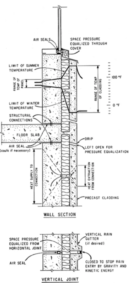
In this way a new approach to wall design is developed in which the main structural element of the wall is located on the warm side of the insulation, with a relatively light external cladding (Figure 1). The main element supports all other components of the wall and thus provides a path whereby heat can be fed to them under winter conditions. The smaller range of
temperature to which the main panel is subjected makes it easier to provide and maintain the necessary air barrier on the warm side of the insulation. All the factors that led to the types of problem described inCBD 93can, therefore, be overcome.
Corrosion of Connections
With the new approach, it may be thought that there will still be a problem of corrosion of the connections supporting the external skin. These connections, however, are working under vastly different conditions from those that prevailed in the old design.
If a member that conducts heat readily passes through the insulation and links an internal component with an external one, it forms a thermal bridge (CBD 44) whose temperature will lie somewhere between those of the internal and external components. The higher rate of heat flow through the bridge, relative to that through the insulation, will draw heat from the inner component and supply heat to the outer at the points of contact, promoting a lateral heat flow in these components. The conditions will stabilize when the rates of heat flow into and out of the bridge are equal, and the mean temperature of the thermal bridge will be biased toward that side which has the easier condition of heat flow.
With a conventionally designed wall there is bound to be an easy path through the massive cold panel for heat to flow away from the connection. With the new approach, the situation is
reversed. The massive, conductive component is now on the warm side feeding heat into the connection, with a comparatively thin component on the cold side to extract heat from it. This is shown diagrammatically in Figure 1. Thus, in the first place, the connection will be warmer than is the case in current practice and more adverse conditions will have to prevail before condensation will occur.
In the second place, the possibility that these conditions will prevail has been reduced. The improved air barrier on the warm side of the insulation will reduce the possibility that moist air from inside the building will flow over the connection. Convection from the building is very unlikely, since this would require two holes in the inner air barrier and an air barrier in the outer skin; this would be contrary to the requirements for rain penetration control.
It is also possible to provide ventilation with outside air should this be considered desirable round the connection. Any air leakage from the building would then be carried away rapidly. Also, should the connection ever become wet from water penetrating to the back of the cladding panel this ventilation would help to dry it quickly. Under winter conditions, the connection will always be warmer than the outside air so that condensation of moisture in the outside air on the connection is impossible.
A Suggested Wall System
In the design and detailing of a wall there is much scope for initiative, ingenuity and individuality. Many types of wall are possible and all will perform satisfactorily provided the basic requirements are met. One possible solution is as follows:
The principal structural wall element will be a quality product of precast concrete. In conformity with the new, scientifically sound approach to the design of walls it will be located on the inside of the total wall complex. Any minor surface blemishes can be touched up either before or after erection to provide an internal face acceptable for decoration. Painting with a heavy-bodied paint or papering the inner face will further increase the airtightness of the panel itself so that the problem of producing an airtight and visually acceptable internal face to the wall will be confined to the joints.
Now that this main element of the wall is located in a warm and thermally stable environment, it is possible to integrate it with the structural system of the building. It is beyond the scope of this Digest to discuss the methods of doing so, but some possible systems can be mentioned briefly. With office-type buildings lateral stability can be obtained from a cast-in-place central elevator core. The wall panels can be stabilized from this core by means of the floor, which can be either cast-in-place or precast. With apartment-type buildings, stability can be obtained from the interior walls, which can be precast as is done in many European types of "system" building. Moment connections between precast elements are more difficult to achieve, but are used in some cases.
The external cladding can be made of thin precast concrete panels of high quality, with possibly only a single connection projecting from their inner face. This connection passes through the insulation to be embedded in the concrete of the main wall panel as it is cast against the back of the insulation. Air spaces between the insulation and the main panel are thus eliminated and no special adhesive is needed. Assembling the cladding on the main panel before erection also minimizes the number of site activities required.
The external cladding panel can be free of all but the most minor cracks and, since it is free to expand and contract, stresses will not be induced that might cause these to open further. The panel can be taken as essentially impervious and special measures for the control of rain penetration can be confined to joints. The natural lack of fit between the insulation and the roughly screened back of the face panel will, however, provide some space for pressure equalization, and for drainage if necessary. Alternatively, the back can be contoured in sympathy with the external face.
Conclusion
An earlier Digest (CBD 93) described some of the problems that have occurred with walls of precast concrete and showed that conventional design and construction practices cannot reasonably be expected to overcome them. This Digest has identified three requirements of a wall that must be met in order to eliminate the problems. Based upon these requirements, a new wall layout is developed using a precast concrete panel as the inside element, with insulation and cladding outside it. It is suggested that the main precast panel should now be integrated with the building structure.