Publisher’s version / Version de l'éditeur:
Vous avez des questions? Nous pouvons vous aider. Pour communiquer directement avec un auteur, consultez la première page de la revue dans laquelle son article a été publié afin de trouver ses coordonnées. Si vous n’arrivez pas à les repérer, communiquez avec nous à [email protected].
Questions? Contact the NRC Publications Archive team at
[email protected]. If you wish to email the authors directly, please see the first page of the publication for their contact information.
https://publications-cnrc.canada.ca/fra/droits
L’accès à ce site Web et l’utilisation de son contenu sont assujettis aux conditions présentées dans le site
LISEZ CES CONDITIONS ATTENTIVEMENT AVANT D’UTILISER CE SITE WEB.
Canadian Building Digest, 1973
READ THESE TERMS AND CONDITIONS CAREFULLY BEFORE USING THIS WEBSITE. https://nrc-publications.canada.ca/eng/copyright
NRC Publications Archive Record / Notice des Archives des publications du CNRC :
https://nrc-publications.canada.ca/eng/view/object/?id=8fbe571f-ac50-405a-948f-00cdad40d4a4
https://publications-cnrc.canada.ca/fra/voir/objet/?id=8fbe571f-ac50-405a-948f-00cdad40d4a4
NRC Publications Archive
Archives des publications du CNRC
For the publisher’s version, please access the DOI link below./ Pour consulter la version de l’éditeur, utilisez le lien DOI ci-dessous.
https://doi.org/10.4224/40000756
Access and use of this website and the material on it are subject to the Terms and Conditions set forth at
Joint movement and sealant selection
Canadian Building Digest
Division of Building Research, National Research Council Canada
CBD 155
Joint Movement and Sealant
Selection
Originally published 1973 G.O. Handegord, K.K. Karpati
Please note
This publication is a part of a discontinued series and is archived here as an historical reference. Readers should consult design and regulatory experts for guidance on the applicability of the information to current construction practice.
Most joints on the exterior of buildings require some form of seal to prevent or minimize the passage of water, water vapour, air, or contaminants. Such seals are usually provided by special flexible materials that bridge the opening and maintain close contact with the separated components, at the same time accommodating in themselves whatever movements take place under the conditions of service.
Sealants have too frequently been thought of simply as plugs for cracks or joints between building components, and only superficial attention has been given to the conditions they must withstand in service. Fortunately, most designers, manufacturers and installers recognize the necessity for a more rational approach to sealant development, selection and application, since they appreciate what a sealant must do and how its role in the system can be quantitatively predicted.
There are a great many sealants on the market and an almost equal number of specific properties to consider in their selection. Of these characteristics and requirements the most important for design purposes are those associated with the ability of the sealant to accommodate anticipated movement. Other special properties and characteristics may influence the final selection and installation, but consideration of movement applies in all cases. The movement capability of a sealant cannot at present, be readily assessed by a single type of test, but categorization in relation to four generic sealant types is generally accepted. Linseed oil putties have a movement capability of plus or minus 1 per cent, butyl rubbers one of plus or minus 5 per cent, solvent curing acrylics one of plus or minus 7.5 per cent and polysulphides, silicones and polyurethane sealants a movement capability of plus or minus 25 per cent. These values indicate the cyclical strain that the sealants can accommodate in service. It can be much less than the static strain that the same materials may withstand during a single stretching or compression.
Estimating Joint Movement
The cyclical strain to which a sealant will be subjected is dependent on the magnitude of the movement at the joint and the width of the sealant. The first prerequisite of sealant selection is
thus an estimate of the nature and extent of the movement to be expected. Once this has been established, consideration can be given to matching the joint width to the sealant's movement capability or to selecting a sealant with characteristics to match the expected or predetermined joint width. Joints in the exterior cladding of buildings tend to exhibit the most extreme cyclical movement. They are also the most critical from the point of view of providing a seal since they are subjected to the most severe service conditions.
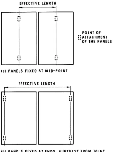
All cladding materials are subjected to seasonal change in temperature and tend to change in dimension accordingly. Joints open in winter and close in summer. Thus, movement at the joint is dependent on the temperature range the cladding panels experience, the coefficient of thermal expansion of the material making up the panel, and the effective length of the panels. The effective length of the panel will depend on the means by which it is fixed to the structure. In panels fixed at their mid-point but otherwise free to move, one half of their length is active in contributing to movement at the adjacent joint. For panels of equal size the effective length contributing to movement at a vertical joint is therefore equal to one panel length (Figure 1(a)). If the panels are fixed only at the ends furthest from the joint, however, the effective length will be close to twice that of the panel (Figure 1(b)). In practice, the situation will probably fall between these two extremes, depending on the fixing points and other intentional and unintentional restraints to panel movement.
Figure 1. Effective panel length, depending on position of attachment.
The maximum temperature that a cladding panel reaches in summer depends on the air temperature, the radiation it receives, the colour of its exposed surface, its thermal capacity, and to some degree the thermal properties of the other components in the wall. The predicted outside surface temperature TS may be taken as the upper limiting value and may be calculated
from the sol-air temperature (CBD 47). As a reasonable approximation, however, the simple relations developed for roofs under solar radiation (CBD 70) may be used.
TS = TA + 100a for low heat capacity panels TS = TA + 75a for high heat capacity panels where TA= maximum air temperature and a is the coefficient of solar absorption of the surface. The maximum air temperature expected in a given locality may be taken as the 2½ per cent July dry bulb design temperature which is listed for most localities in Supplement No. 1 to the National Building Code of Canada. Values of the coefficient of solar absorption range from 0.95 for a black surface to 0.45 for clean white surfaces (Table I, CBD 70).
The minimum surface temperature of a wall panel in winter is close to the minimum air temperature. The panel does not lose so much heat to the clear night sky as a roof does and usually receives long-wave radiation from adjacent buildings. The 1 per cent January design temperature listed in Supplement No. 1 provides a close approximation.
Example
In Winnipeg, Manitoba, the 2½ per cent July DB is 87°F and the one per cent January design temperature -28°F. A thin black wall panel under peak solar radiation can reach a temperature of 87 deg + 100 (0.95) = 182°F in summer and fall to a temperature of -28°F in winter. Thus each year it can go through a range of temperature of 210 F deg.
If the panel is of steel, fixed at the mid-point, with a coefficient of thermal expansion of 7 x 10 -6 in./in. °F and a total effective width of 10 ft. (120 in.), the total change in the width of the
joint summer to winter is 7 x 10-6x 120 x 210 deg = 0.176 in.
If a sealant with a movement capability of ±25 per cent is considered for this joint, it will allow a total yearly percentage movement of 50 per cent. Thus the minimum joint width can be estimated by dividing the predicted annual movement of 0.176 by 0.50, giving 0.35 in. A joint width of approximately 3/8 in. should allow the joint to operate without exceeding the capability of the sealant.
If a sealant having a movement capability of ±7.5 per cent is to be used, the joint width will have to be increased to 0.176/0.15 = 1.17 in. in order to avoid premature failure of the sealant in cyclical extension and compression.
If linseed oil putty with a movement capability of, only ±1 per cent were to be insisted upon, a joint width of 8.8 in. would be necessary.
The minimum required joint width varies in direct proportion to panel size. For the panel used in the example, the required joint width for a 20-ft. wide panel is ¾ in. and for a 50-ft. panel it is 1¾ in. when a sealant with ±25 per cent movement capability is used.
With panels made of porous material the effects of moisture expansion and contraction are also involved. In most situations it is probable that movements resulting from moisture change will tend to act in the opposite direction to those caused by temperature change. High moisture contents resulting from condensation on exterior panels will occur in winter when the panel is contracting due to a lowering of temperature. Similarly, low moisture contents producing shrinkage will be experienced in summer when the panel is at a high temperature. The coincidence of high temperatures and rain is most unlikely except for brief periods. The combination of thermal and moisture movements for panels of porous material should thus result in a net movement less than that predicted on the basis of temperature change alone.
Installation Temperature
The foregoing design approach assumes that the sealant will be installed when the adjacent panels are at a temperature half way between their maximum and minimum values. This being the case, the sealant will operate within its movement capability, in tension in winter and in compression in summer, as in Figure 2(a).
Figure 2. Potential effects of temperature conditions at time of sealant application.
If it is installed when the panels are at a much lower temperature, offering a wider joint, the sealant will experience a greater strain in compression than in tension, as in Figure 2(b). It will be less likely to fail, however, because the maximum tensile strain it undergoes will be reduced and its adhesion to the surface will be augmented by the predominance of compressive forces. Failures could occur if the joints were very narrow or the sealant put in place at extremely low temperatures. Under these conditions, high tensile strains could be induced at the sealant surface by excessive extrusion of the sealant from the joint.
If the temperature at the time of installation is higher than the average temperature as represented in Figure 2(c), the sealant will experience an increased strain in tension during winter when the sealant material itself will also be somewhat harder and less capable of extension. The minimum joint width as specified originally might have to be increased in anticipation of this situation.
Some compensation for the effects of installing a sealant at higher than ideal temperatures might be realized by using sealants such as silicones and two-part polysulphides that do not reach a set condition until a few hours after installation when cooler night temperatures prevail. The possibility of similar compensation for the slower-curing compounds such as one-part polysulphide and two-part polyurethane is impossible to predict.
The potential irreversible movement in building components is another factor that should be considered in estimating joint widths for sealant installation. Shrinkage that occurs prior to sealant installation could increase the joint width and thus be an advantage. Creep deflection of members or expansive effects in materials may act to decrease the joint width, however, and necessitate increased width allowance.
The performance of field-moulded sealants, with regard to cyclical deformation and other operating features, is also influenced by the shape, dimensions and location of the sealant bead as well as by surface preparation and other installation techniques (CBD 96). Additional factors may need to be taken into consideration in selecting, installing and maintaining sealants for
specific situations. The "Guide to Joint Sealants for Concrete Structures" prepared by A.C.I. Committee 504 covers in much more detail the special properties of individual sealants, details of joints, and installation and repair of sealing systems.
Conclusion
This Digest attempts to deal with the movement considerations involved in the selection of sealants for exterior joints. The primary principle that emerges is that the joint width should not be less than the minimum required for the sealant that is to be used. In terms of utilizing the sealant to maintain a seal under cyclical loading, the wider the joint, the better; but practical considerations of cost of sealant and the potential for sag in very wide joints must be recognized during the design process.
One approach that could reduce the necessary joint width would be to increase the movement capability of the sealant by utilizing a lap-joint in which the sealant is stressed in shear, as in Figure 3. The advantage of using the sealant in shear instead of in tension results from the fact that the modulus of elasticity in shear is about one third that in tension under ideal conditions. For a given deformation the stress imposed on the sealant in shear is considerably less than that in tension.
Figure 3. Sealant utilized in shear.
A design approach based on achieving a specified minimum joint width for a particular sealant and panel combination may appear, at first, to be academic in view of the difficulties of achieving accurate joint dimensions in actual construction. A requirement that joint widths be not less than a specified minimum allows some flexibility in construction tolerances, if only in one direction. As the achievement of final joint widths at least equal to the minimum is critical in terms of the potential sealant performance, changes in established construction techniques may sometimes be necessary. Failing this, panels might have to be cut or sawn to increase the width of an "as built" joint that is too narrow.
One other solution is to redesign completely the jointing system of exterior walls by moving the sealant to an inner location in the joint system where a less demanding environment exists, and allowing open joints with less critical dimensions at the exterior face. At an inside location cyclical movement is reduced, the sealant is protected from extremes of weather, and tolerances in joint width are more readily controlled (CBD 40, CBD 120).
Bibliography
Climatic Information for Building Design in Canada, 1970. Supplement No. 1 to the National Building Code of Canada, Associate Committee on the National Building Code, National Research Council of Canada, Ottawa. NRCC 11153.
Guide for Sealed Joint Design. K. K. Karpati. National Research Council of Canada, Division of Building Research, Tech. Paper No. 385, Ottawa. January 1973. (NRCC 13027).
Guide to Joint Sealants for Concrete Structures. Journal, American Concrete Institute, Vol. 67, July 1970, p.489-536.