3D Modeling with Silhouettes
by
Alec Rivers
Submitted to the Department of Electrical Engineering and Computer
Science
in partial fulfillment of the requirements for the degree of
Masters of Science in Computer Science and Engineering
at the
MASSACHUSETTS INSTITUTE OF TECHNOLOGY
February 2010
@
Massachusetts Institute of Technology 2010. All rights reserved.
I Ai
A uthor ..
...
Department of Electrical Engineering and Computer Science
January 29th, 2010
Certified by...
Fredo Durand
Associate Professor
Thesis Supervisor
Accepted by ... ... I*-. ....Terry P. Orlando
Chairman, Department Committee on Graduate Students
ARCHivES
MASSACHUSETTS INSTrTUTE OF TECHNOLOGY
FEB 2 3 2010
3D Modeling with Silhouettes
by
Alec Rivers
Submitted to the Department of Electrical Engineering and Computer Science on January 29th, 2010, in partial fulfillment of the
requirements for the degree of
Masters of Science in Computer Science and Engineering
Abstract
With the increasing power of computers and the spread of dedicated graphics hard-ware, 3D content has become ubiquitous in every field, from medicine to video games. However, designing 3D models remains a time-consuming and costly process, so far limited mainly to professionals who have trained extensively with complex modeling suites. We present a new sketch-based modeling approach which aims to make this process simpler and cheaper for professionals, while also making it easy enough for amateurs to use. In our approach, models are interactively designed by drawing their 2D silhouettes from different views. The core idea of our paper is to restrict the input to 2D operations, removing the need to explicitly create or position 3D elements. To create complex shapes, we allow the user to perform CSG operations on silhou-ettes. We introduce a new algorithm to handle CSG operations that leverages special properties of silhouette cylinders to convert the CSG problem into one that can be handled entirely with 2D operations, making implementation much simpler and more robust. We also introduce a smoothing operator that can generate a smooth shape that matches a set of input silhouettes. We evaluate our approach by using it to model a random sampling of man-made objects taken from the words in WordNet, and show that all of the tested man-made objects are suitable to being modeled quickly and easily using their silhouettes. We also present a user study that demonstrates that novice users are able to use our implemented modeler more effictively than Google SketchUp, a leading commercial 3D modeler also aimed at novice users.
Thesis Supervisor: Fredo Durand Title: Associate Professor
Acknowledgments
I would like to thank Professor Durand, my current adviser, as well as Professor Takeo Igarashi of the University of Tokyo, who was advising me when I started this project. I'd like to thank the graphics groups of MIT and the University of Tokyo for their feedback. I'd like to thank Professor Doug James of Cornell for starting me on the path to academia. I'd like to thank my family for their encouragement and my cat Zeke for giving me support.
Contents
1 Introduction 11
2 Related Work 13
2.1 Sketch-Based Modelers... . . . . . . . ... 14
3 User Interface 15 3.1 Constructive Solid Geometry... . . . . . . . . . 16
3.2 Smoothing... . . . . . . . . 17
3.2.1 2D Smoothing... . . . . . . ... 17
3.2.2 Beveling... . . . . . 17
4 Algorithms 19 4.1 Calculating the Visual Hull... . . . ... 20
4.2 Extension to Arbitrary CSG Trees... . . ... 22
4.3 Smoothing... . . . . . . . . 23
4.3.1 Enforcing Rims... . . ... 24
4.3.2 Minimizing Variation of Laplacian Magnitude.... . . ... 24
5 Results 27
6 User Study 31
List of Figures
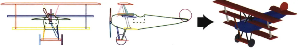
1-1 Intersecting 2D silhouettes: The two silhouettes on the left were used to automatically generate the 3D model on the right. Note that the line drawings are not projections of the 3D model, but rather the input that generates the model. . . . . 11
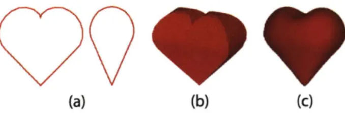
3-1 Constructive solid geometry: A coffee mug assembled from input silhouettes using CSG operations... . . . ... 15 3-2 Smoothing: Input silhouettes (a) are intersected to find a sharp shape
(b) which is then smoothed while preserving the specified silhouettes (c ) . . . . 1 7 4-1 Finding the visual hull: (a) Two silhouette cylinders defined by a
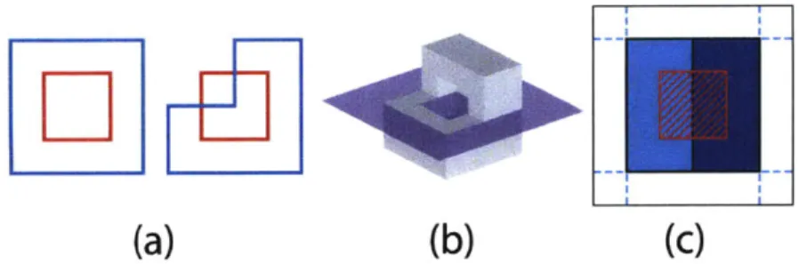
circle and and L shape are intersected to produce a 3D shape. (b) The intersections of the cylinders with the middle horizontal plane are used to generate a semicircular facet... . . . . . ... 20 4-2 CSG operations: the red cube is being subtracted from the L-shape.
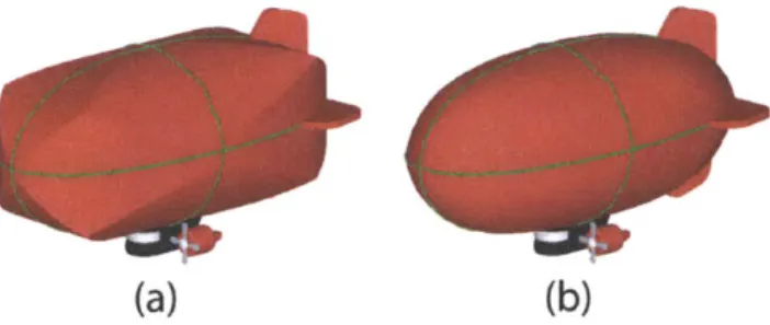
(c) Examining the cross-section through the illustrated plane. .... 21 4-3 Rim calculation: The rims are calculated based on the unsmoothed
shape (a), and then locked in place while smoothing occurs (b). . . . 23
5-1 Complex scene: Every model in this image was designed and com-posited using our implemented modeler. Rendering was performed separately using a commercial package. . . . . 28
6-1 User study models: Here we show for each object in our user study the middle-ranked model done using our approach and done using SketchUp... . . . . . . . . . . . 31 6-2 User study results: Each column represents a different ranking of
models done in the user study, with the highest-quality models at the top and the lowest-quality at the bottom. Green boxes indicate mod-els designed with our approach; red boxes are modmod-els designed with SketchU p. . . . . 32
Chapter 1
Introduction
We present a new sketch-based modeling approach that facilitates the creation of 3D models of man-made objects and targets amateur and professional users. Our work is motivated by observing the workflow of traditional CAD, where design usually proceeds in two phases. A designer first sketches an object in 2D, often from front, side, and top views, and then uses these sketches as a reference in constructing a 3D model a computer. While most of the creative designing occurs in 2D, the process of translating those 2D sketches into a 3D model is tedious, and often takes the most time. The 3D position for every element of the model must be specified, and when referring to sketches, the designer must be constantly translating a desired change in a 2D view to the sequence of 3D operations that will produce that change.
We propose a new approach that can construct a 3D model directly from 2D
draw-Figure 1-1: Intersecting 2D silhouettes: The two silhouettes on the left were used
to axtomatically generate the 3D model on the right. Note that the line drawings are not projections of the 3D model, but rather the input that generates the model.
ings of an object from different views, eliminating the transfer step. The core idea that makes our approach tractable, from both a user interface and implementation perspective, is to focus on object silhouettes.
From the user's point of view, silhouettes are simpler than full-fledged 2D drawings and alleviate the need for explicit correspondence between views. The user specifies a shape by drawing its silhouettes in two or more orthographic views, and a 3D shape that matches those silhouettes is automatically generated and displayed. A user can therefore focus on iterating the 2D drawings, allowing much faster experimentation and modeling.
From an algorithmic standpoint, we show that silhouettes dramatically simplify the computation of one of the most challenging features in CAD-CAM: Boolean opera-tions, a.k.a. Constructive Solid Geometry (CSG). Building on ideas from the visual hull and silhouette intersection, we introduce simple algorithms that operate entirely in 2D but can generate complex 3D CSG objects. We also enable the creation of smooth shapes that approximate the least-variation-of-curvature surfaces that match their input silhouettes.
Chapter 2
Related Work
We use a 3-view interface similar to existing CAD modeling systems, e.g. [20, 15, 1]. Unlike these programs, in our approach, the three views are used solely as canvases for sketching 2D silhouettes. Sketching is the only input tool, and there is no need to perform any 3D operations, or to specify the exact positions of 3D elements. To generate the surfaces corresponding to input silhouettes, we build upon the concept of the visual hull and silhouette intersection [8, 12, 11, 9, 21, 3]. Whereas the visual hull has previously been used mainly to reconstruct 3D shapes from video or image capture, we introduce its use as a modeling tool. Furthermore, while the visual hull involves only intersections, we support the application of arbitrary CSG trees to cylinders generated by silhouettes. We also allow the user to construct a complex model out of simpler parts (see Figure 1-1), preventing artifacts from self-occlusion which can arise when using the visual hull on silhouettes from images.
Our approach shares some similarities with systems developed to convert drafted wireframe representations of objects to CAD models [17, 22, 2]. These were mainly offline systems that involved processing an input sketch with no correspondences to infer the set of all possible implied 3D models. Our approach, by comparison, is interactive, generates just one 3D model, and maintains explicit associations between silhouettes in different views. Our approach can also handle a wider range of input
silhouettes, can generate a wider range of geometry, arbitrary topology, and smoothed shapes.
2.1
Sketch-Based Modelers
2D sketching has recently been leveraged as a powerful tool for 3D modeling [4, 13,
7,
6, 23, 19, 18, 5, 10] and editing [14]. In most previous sketch-based modelers, the model was represented by a 3D construct (e.g. a mesh or a set of curves), and 2D sketches were used to modify that 3D construct by rotating around the model in a 3D view and drawing into the scene. By comparison, in our approach, the model is represented by 2D drawings, and the 3D model is not required as a context for further 3D sketching. This allows the user to work on persistent 2D views which can be edited in any order, and avoids the need for constant 3D rotation. The orthographic views also make it easier to design man-made, axis-aligned objects than with previous freeform sketch-based modelers.To achieve smooth shapes, we build on the algorithms presented in FiberMesh, which introduced way to compute a smooth mesh that connects a set of 3D curves. We
introduce a special form of FiberMesh-style smoothing that smooths the mesh while maintaining the original silhouettes. We use this method to obtain a smooth shape that matches the input silhouettes.
Chapter 3
User Interface
In our approach, a 3D model is assembled out of parts. Each part is specified by two or three silhouettes from front, side, or top views. As the user creates and refines the silhouettes of a part, the corresponding 3D model is automatically generated and displayed. For example, if the user sketches a triangle in the front and side views, and a square in the top, a pyramid will appear in the 3D view. The calculation is fast enough to provide immediate feedback. Our implemented interface allows the user to specify silhouettes only from orthographic views, as this is a natural and well-understood modeling approach; however, our algorithms can work with silhouettes from any view.
A shape with complex or occluded segments is built up by composing it out of indi-vidual parts. This matches a natural 2D drawing approach of splitting objects into parts, and also sidesteps what would otherwise be a major problem of
underspec-Figure 3-1: Constructive solid geometry: A coffee mug assembled from input
silhouettes using CSG operations.
ification. Because shapes match their silhouettes exactly, the connections between adjacent parts are exact.
Parts need not have silhouttes specified for all views. For views in which no silhouette is specified, a bounding box is calculated from the other views and drawn in gray in the missing views. This helps the user position other parts relative to that part in that view. This bounding box also allows us to calculate correct Z-ordering of silhouettes in other views.
A part's silhouette in one view imposes certain constraints on the part's silhouettes in the other views. For example, the height of a part's silhouette in the side view should match the height of the part's silhouette in the front view. While a part is selected, these constraints are illustrated as guidelines showing the maximum and minimum extents of the silhouette in the X and Y directions. These constraints are not enforced during the drawing process, however; if an artist draws past the boundaries, the program will allow it, but will cut the polygon internally before generating the 3D model.
3.1
Constructive Solid Geometry
Parts can be combined using regularized Boolean operations, as described in [16]. In our interface, we allow union and subtraction operations, though our algorithm can also work with arbitrary CSG trees. This allows for the creation of objects that cannot be fully specified by just their exterior silhouettes. For example, a coffee cup has a concavity that can never be seen from any exterior silhouette, but that can be constructed by subtracting one cylinder from a larger cylinder (see Figure 3-1).
(a)
(b)
(c)
Figure 3-2: Smoothing: Input silhouettes (a) are intersected to find a sharp shape (b) which is then smoothed while preserving the specified silhouettes (c)
3.2
Smoothing
Shapes constructed purely from CSG operations on silhouettes will always have sharp facets. However, we allow the user to toggle for each part whether the desired shape is sharp or smooth. A smoothed part generates an approximation of the smoothest possible shape that satisfies the input silhouettes. This is illustrated in Figure 3-2. Smoothing operations are performed strictly after CSG operations: a smoothed object cannot be unioned with or subtracted from any other, but an object that is composed out of CSG operations can be smoothed.
3.2.1
2D Smoothing
Smooth surfaces will by default minimize the variation of curvature in both principal curvature directions. However, the user can specify that a part should minimize variation of curvature only around one axis. The primary purpose of this is to allow the construction of solids of revolution, though actually it supports a slightly more general class of shapes (e.g., solids of revolotion that have been stretched in one axis).
3.2.2
Beveling
Each part (excluding smoothed parts) can be optionally beveled as a post-processing step. We use a standard approach to beveling, the algorithm for which is outside the scope of this thesis.
Chapter 4
Algorithms
Traditionally, calculating Boolean operations on arbitrary polyhedra involves many special cases, and an error in one part of the mesh can make it impossible to gen-erate the correct surface elsewhere. It is notoriously difficult to produce a robust implementation.
In this chapter, we present a simple and robust algorithm that can caluclate the solid resulting from an arbitrary CSG tree applied to silhouette cylinders (the orthographic equivalent of silhouette cones). Our algorithm builds on the work of [12, 11], which showed that finding the visual hull (the intersection of silhoutte cylinders) could be done using 2D operations.
In fact, we show that the computation of CSG trees over silhouettes can similarly be computed using only 2D operations. This includes calculating the visual hull, which is simply a Boolean intersection of silhouette cylinders, and arbitrary Boolean operations on visual hulls, which is the application we use the algorithm for in our modeling approach.
We also introduce an algorithm for smoothing a shape constructed from silhouettes. This smoothing operation attempts to minimize the variation of Laplacian magnitude, as in [13], but generates a surface that still has the original input silhouettes.
(a)
(b)
Figure 4-1: Finding the visual hull: (a) Two silhouette cylinders defined by a
circle and and L shape are intersected to produce a 3D shape. (b) The intersections
of the cylinders with the middle horizontal plane are used to generate a semicircular
facet.
4.1
Calculating the Visual Hull
The facets of a CSG solid are a subset of the facets of the input shapes. Our algorithm
proceeds by examining each plane on which one or more input facets lie and using 2D
operations on the plane to calculate what part of the plane is a surface of the CSG
solid.
We first process the input silhouette cylinders to find the set of planes on which any
input facets lie. Then, for each plane, we process the intersection of the plane with
each silhouette cylinder separately. For each silhouette cylinder c, we find two 2D
polygons: ic, the intersection of the plane and the cylinder, and se, the union of any
of the cylinder's facets that lie completely on the plane. s, is contained within ic.
In Figure 4-1, we illustrate these terms by showing the intersection a plane with the
shape defined by the intersection of a circle silhouette and an L-shaped silhouette.
The solid lines on the plane indicate the ic for the red and green silhouette cylinders,
while the shaded green rectangle is
sgreen.If a silhouette is not perpendicular to the plane, finding ic is simply a matter of
casting the silhouette onto the plane. This is visible in Figure 4-1 with
ired.If they
are perpendicular, as with the green silhouette, we intersect the silhouette with the
2D line that is the plane's projection into image space (the black line in Figure 4-1
(a)) for that silhouette, resulting in a set of line segments which we extrude infinitely
(a)
(b)
(c)
Figure 4-2: CSG operations: the red cube is being subtracted from the L-shape. (c) Examining the cross-section through the illustrated plane.
on the plane to generate ic.
Finding se is straightforward. The cylinder facets that lie entirely on the plane must belong to silhouettes perpendicular to the plane. For each such silhouette, the seg-ments of the silhouette that lie on the plane's projected line are the ones that have corresponding facets on the plane. These facets are just the rectangles defined by those segments' infinite extrusions in the silhouette's viewing direction.
Once we have ic and se relative to the plane for all the silhouette cylinders, we can compute i, and s,, the polygons for the interior and surface of the CSG solid on this plane. We first show the calculation for the case when the solid is the intersection of two silhouette cylinders:
i =
ii
ni
2(4.1)
S
=(s
1 Us
2)
n i,
(4.2)
In the case of Figure 4-1, performing the above operations yields the grey semicicle, which is the surface of the intersection (the visual hull) generated by that plane. Computing the se for all the other planes on which a facet may lie will result in generating all of the facets of the visual hull. (The smooth circle can be discretized into an ngon.)
4.2
Extension to Arbitrary CSG Trees
We now show how to calculate i, and s, for union, subtraction, and XOR operators. These operators can then be applied in sequence to process an arbitrary CSG tree. Union:
ip = il U i2 (4.3)
S, = (Si - (i2 - S2)) U (s2 - (i1 - Si)) (4.4)
Equation 4.4 follows from the intuition that the surface produced by a union of two shapes is the part of the first surface that does not lie strictly within the second shape, combined with the part of the second surface that does not lie strictly within the first shape.
Subtraction:
i, = (ii - i2) U s 2 (4.5)
S, = (Si - (i2 - S2)) U (s2 0 i1) (4.6)
XOR: XOR can be implemented as a combination of union and subtraction oper-ators: A e B = (A - B) U (B - A).
One final refinement must be made to handle the case when two surfaces overlap. To handle this case, we separately record for each cylinder-plane intersection separate copies of s, corresponding to surface facets with a positive normal relative to the plane and with a negative normal relative to the plane. The normal can be determined for the facet of an individual input cylinder easily. For derived CSG solids, we carry out the above surface operations twice for each plane, once on the positive input surfaces to calculate s+ and once on the negative surfaces to calculate s-. When adding facets to the mesh, we can then generate separate facets with positive and negative normals. Optionally, we can subtract (s+
n
s-) from s+ and s- to avoid generating an infinitely(a)
(b)
Figure 4-3: Rim calculation: The rims are calculated based on the unsmoothed
shape (a), and then locked in place while smoothing occurs (b).
thin, double-sided surface.
4.3
Smoothing
In this section we present an algorithm for smoothing a shape defined by silhouettes
that preserves the original input silhouettes. We build on the smoothing algorithm
of [13].
The first step in smoothing is to remesh the visual hull to enable it to be smoothed.
This is done by intersecting each facet with a regular grid of squares projected flat
onto the facet's surface. This results in each facet being split into a collection of
small patches, suitable for smoothing. We take care to ensure that the generated
mesh remains watertight along seams between facets.
Ensuring that a mesh maintains its silhouettes as it smooths is difficult. One way a
mesh could fail to satisfy its silhouettes is if it expands beyond its silhouettes during
smoothing. We preclude this possibility by only allowing each vertex to move in the
direction opposite to its normal. That leaves the more tricky problem of a mesh
shrinking to the point that it no longer satisfies a silhouette.
4.3.1
Enforcing Rims
A single point on a given silhouette defines a line in 3D space that passes through that point and extends infinitely in the viewing direction of that silhouette. We refer to this as the point's rim line. A mesh has shrunk too much if there exists a silhouette point for which the rim line never touches the mesh. To ensure that a mesh continues to match its silhouette as it is smoothed, we explicitly calculate a point on each rim line and lock it in place before smoothing. We call these points the rim points, or collectively the rims, an established term for the positions at which a smooth shape touches its visual hull.
It may be tempting to propose calculating rims on the fly during smoothing. We experimented with this approach, but found that it generates noisy placements, and rims that appear to be good candidates during initial smoothing may not generate the intuitively expected 3D shape.
Our algorithm for calculating rim points is straightforward. Conceptually, every point along each silhouette should corresond to a rim point on the visual hull. In practice, because the mesh is composed of discrete triangles, this is not necessary. We consider only rim lines that pass through a vertex of the remeshed model. For each of these rim lines, we calculate its intersection with the unsmoothed model, resulting in a set of line segments. We then place a rim point at the center of each of these segments. The mesh must then be re-tesselated to include these points. Although this rim-finding system may seem simplistic, we have found it to work well in practice (see Figure 4-3).
4.3.2
Minimizing Variation of Laplacian Magnitude
We take the approach to smoothing described in FiberMesh and apply it as a sequence of simple smoothing iterations. Each iteration updates the positions of the vertices
as follows:
ci = xi Li (4.7)
c'=
IriIci
(4.8)
jENj
x'=xi
+
c'ni (4.9)where xi is the position of vertex i, Ni is the set of neighbor vertices connected to vertex i, Li is the discrete graph Laplacian of the mesh at vertex i, and ci is the estimated curvature at vertex i. Rim vertices are locked in place. This update step is applied repeatedly until the greatest change of position for a vertex in the mesh is less than some threshold. This converges to an approximation of the least-squares solution to minimizing the variation of Laplacian magnitude across the mesh.
2D smoothing as described in Section 3.2.1 is achieved by limiting Ni for each vertex to the subset of connected vertices that lie at the same depth relative to the smoothing plane.
Chapter 5
Results
Using only 2D input reduces by one dimension the challenge of constructing a 3D model, making the process easier and faster for the user. Furthermore, allowing CSG operations removes a major limitation of visual hulls, which is that they can-not express concavities in which both principal curvatures are negative. With CSG operations, one could theoretically assemble any object with flat facets by unioning together large numbers of small, easily-specified elements (for example tetrahedra). In practice, our approach works best with objects that have axis-aligned or smooth surfaces. Designing objects with rough or complex surface detail requires specifying many silhouettes or many CSG operations to specify all of the details. Similarly, complex smooth shapes that cannot be split into parts, for example animals, are also difficult to model, because without splitting them in to parts there is no good way to specify all of the surface details.
Man-made objects are often strongly axis-aligned, have simple surfaces, and naturally decompose into simpler subparts. We believe that this makes them naturally suited to being modeled using our approach. We furthermore hypothesize that the great majority of man-made objects can be modeled quickly and accurately with parts
defined solely by their silhouettes.
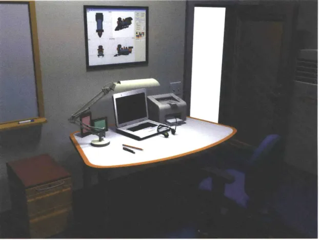
Figure 5-1: Complex scene: Every model in this image was designed and compos-ited using our implemented modeler. Rendering was performed separately using a commercial package.
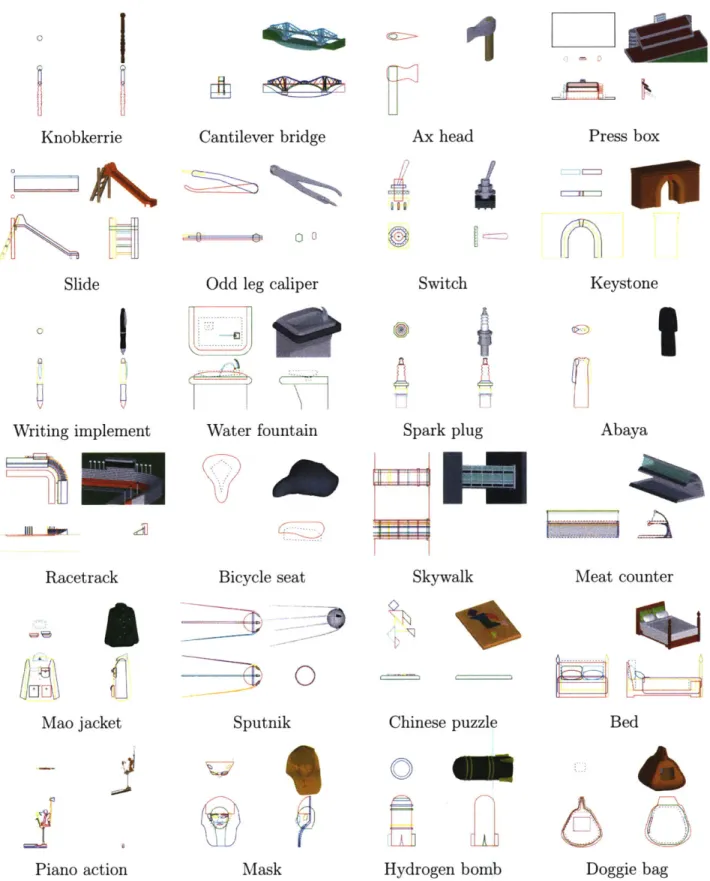
using our approach. We used WordNet to generate a list of random hyponyms of the word "artifact", in the meaning of a physical entity created by man, which we believed would fairly sample all man-made objects. We used Google search to select an image of the given object, selecting from the first page of either web or image search results. We then created a 3D model of the object, using the image as a reference. We proceeded in order down the list, only skipping words that did not correspond to concrete physical objects (8 of the first 32 words generated).
In Table 5.1 we show the models created for each word. Models were created by two individuals, neither of whom had significant previous 3D modeling experience. The average time to create a model was 25.2 minutes, with a standard deviation of 10.6 minutes.
In our approach, individual subparts must be axis-aligned, but they can be rotated relative to one another to create complex shapes. To illustrate the total level of complexity possible with our approach, we modeled an office scene, shown in Figure 5-1, entirely using our modeling system. This scene demonstrates that our approach scales well to complex scenes.
I1
Knobkerrie
Slide
Writing implement
Racetrack
Cantilever bridge
.0 0 oOdd leg caliper
Water fountain
Bicycle seat
Ax head
Press box
4~~
Switch
Spark plug
Skywalk
Keystone
Abaya
Meat counter
0
Chinese puzzle
0
Piano action
Mask
Hydrogen bomb
Doggie bag
Table 5.1: Evaluation: A random sampling of man-made objects modeled using
our approach, shown with the silhouettes that generate them. Dashed silhouettes
represent subtracted shapes. The average time to create a model was 25.2 minutes,
with a standard deviation of 10.6 minutes.
30
Mao jacket
Sputnik
Bed
Chapter 6
User Study
Finally, we ran a user study to test our belief that users find modeling in 2D with
silhouettes easier than modeling in a 3D view with 3D operations. We compared
our approach to that of SketchUp [19], which is a 3D modeler also aimed at novice
users, but which uses a single 3D view, in which users model by drawing lines on a
3D surface and extruding shapes.
Our user study involved ten participants, recruited from the general population, all
of whom were familiar with computers but none of whom had previous experience
doing 3D modeling. Each participant spent twenty minutes following a tutorial of our
modeler, and twenty minutes following a tutorial provided by Google for SketchUp,
in randomized order. The participant was then shown a series of three photographs
Oddleg caliper
Slide
Press box
Our modeler
SketchUp
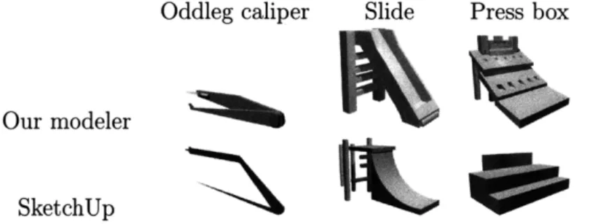
Figure 6-1: User study models: Here we show for each object in our user study
the middle-ranked model done using our approach and done using SketchUp.
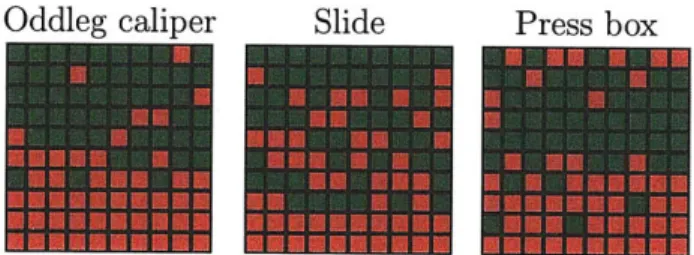
Oddleg caliper Slide Press box
Figure 6-2: User study results: Each column represents a different ranking of models done in the user study, with the highest-quality models at the top and the lowest-quality at the bottom. Green boxes indicate models designed with our ap-proach; red boxes are models designed with SketchUp.
of objects: an oddleg caliper, a slide, and a pressbox. These were selected from the random list of objects used in the evaluation mentioned above, and were chosen due to their wide range of scales and complexity. The participant modeled each of these objects in sequence, spending a maximum of 25 minutes on each, or until the user felt that the model was complete. The participant switched between using our mod-eler and SketchUp, never modeling the same object twice (each participant therefore created a total of three models). Half the participants started with SketchUp, and half with our modeler. The study lasted approximately two hours for each user. We show the resulting models in Table 6.1.
In a second phase of our user study, ten people who had not participated in the first part were were asked to sort rendered images of every model created into a total ordering by quality. The rendered images were produced in a third-party commercial renderer and could not be distinguished as to which modeler was used to create them. In Table ??, we show the results of these rankings, illustrating that models done
with our modeler were consistently ranked higher than models done with SketchUp. To quantify this, we calculated for each ranking all the pairs of a model done with our modeler against a model done with SketchUp. We found that on average in 83% of the pairs the model done with our modeler ranked higher.
However, these statistics are obscured by the fact that users had different levels of overall skill, so a highly skilled user's models would often outrank models done by less skilled users, regardless of the relative ease of use of the two approaches. We
therefore calculated what percentage of users had better average rankings with our modeler than with to SketchUp. We found that every single user in our study had better averages with our approach. For users that did two models with our approach and one with SketchUp, both models done with our approach ranked higher than the SketchUp model in all cases; for users that did one model with our modeler and two with SketchUp, the one with our modeler ranked higher than both of the models done with SketchUp in all cases.
Our modeler
SketchUp
Our modeler
Our modeler
~tK
Table 6.1: User study models: The set of all models generated by our ten users.
Note that five users started with our modeler, while the other five started with
SketchUp.
SketchUp
SketchUp
Chapter
7
Conclusions and Future Work
We proposed the use of 2D silhouettes as a modeling tool. We presented an algorithm for robustly calculating CSG operations on cylinders defined by 2D silhouettes, and for generating a smooth shape that matches a set of silhouettes.
We believe that the models in Table 5.1 demonstrate that the majority of man-made objects are amenable to being modeled quickly and easily using our approach. Each object could be broken down into subparts which were easily specified from their silhouettes. However, cloth objects suffered in fidelity, as it was hard to capture the complex deformations of their surfaces from their silhouettes. We can gain additional control of smoothing by refining a shape using CSG operations prior to smoothing, which we used to achieve defined cheekbones on the smooth face of the mask. Aside from smoothing settings, the models are entirely specified by their silhouettes, which are shown. Therefore, any user who could can those 2D drawings can create the corresponding 3D models. The simplicity of the 2D drawings illustrates what we believe to be the power of silhouettes as a modeling tool.
We believe that the results of the user study (Figures 6-1, 6-2 and Table 6.1) show that novice users were able to design measurably better models using our approach than using SketchUp. As SketchUp is a leading modeler aimed at new users, we believe that this is a valid comparison, and demonstrates the effectiveness of our
approach.
The robustness and simplicity of our CSG algorithm makes it attractive for many applications. In future work, it could be extended to support a larger class of shapes: in general, we believe the outlined algorithm would work with any solid for which (1) the planes of all of its facets are known, and (2) it is possible to easily compute its intersection with a plane, including determining what part of the plane lies on the solid's surface.
Bibliography
[1] CATIA. Dassualt systemes. 2009.
[2] Zen Chen and Der-Baau Perng. Automatic reconstruction of 3d solid objects from 2d orthographic views. Pattern Recogn., 21(5):439-449, 1988.
[3] Jean-Sebastien Franco and Edmond Boyer. Exact polyhedral visual hulls. In
Proceedings of the Fourteenth British Machine Vision Conference, pages
329-338, September 2003. Norwich, UK.
[4] Takeo Igarashi, Satoshi Matsuoka, and Hidehiko Tanaka. Teddy: a sketching interface for 3d freeform design. In SIGGRAPH '99: Proceedings of the 26th
annual conference on Computer graphics and interactive techniques, pages
409-416, New York, NY, USA, 1999. ACM Press/Addison-Wesley Publishing Co. [5] Levent Burak Kara and Kenji Shimada. Sketch-based 3d-shape creation for
industrial styling design. IEEE Comput. Graph. Appl., 27(1):60-71, 2007. [6] 0. Karpenko, J. F. Hughes, and R. Raskar. Free-form sketching with variational
implicit surfaces. Computer Graphics Forum, 21(3):585-594, 2002.
[7] Olga A. Karpenko and John F. Hughes. Smoothsketch: 3d free-form shapes from
complex sketches. In SIGGRAPH '06: ACM SIGGRAPH 2006 Papers, pages 589-598, New York, NY, USA, 2006. ACM.
[8] A. Laurentini. The visual hull concept for silhouette-based image understanding.
[9] Svetlana Lazebnik, Yasutaka Furukawa, and Jean Ponce. Projective visual hulls.
Int. J. Comput. Vision, 74(2):137-165, 2007.
[10] M. Masry, D. Kang, and H. Lipson. A freehand sketching interface for progressive construction of 3d objects. In SIGGRAPH '07. ACM SIGGRAPH 2007 courses, page 30, New York, NY, USA, 2007. ACM.
[11] Wojciech Matusik, Chris Buehler, and Leonard McMillan. Polyhedral visual hulls for real-time rendering. In Proceedings of the 12th Eurographics Workshop
on Rendering Techniques, pages 115-126, London, UK, 2001. Springer-Verlag.
[12] Wojciech Matusik, Chris Buehler, Ramesh Raskar, Steven J. Gortler, and Leonard McMillan. Image-based visual hulls. In SIGGRAPH '00: Proceedings
of the 27th annual conference on Computer graphics and interactive techniques,
pages 369-374, New York, NY, USA, 2000. ACM Press/Addison-Wesley Pub-lishing Co.
[13] Andrew Nealen, Takeo Igarashi, Olga Sorkine, and Marc Alexa. Fibermesh: de-signing freeform surfaces with 3d curves. In SIGGRAPH '07: A CM SIGGRAPH
2007 papers, page 41, New York, NY, USA, 2007. ACM.
[14] Andrew Nealen, Olga Sorkine, Marc Alexa, and Daniel Cohen-Or. A sketch-based interface for detail-preserving mesh editing. ACM Trans. Graph., 24(3):1142-1147, 2005.
[15] Pro/ENGINEER. Parametri technology corporation. 2009.
[16] A. A. G. Requicha. Mathematical Models of Rigid Solid Objects. Number 22 in Production Automation Project. 1977.
[17] Hiroshi Sakurai and David C. Gossard. Solid model input through orthographic views. SIGGRAPH Comput. Graph., 17(3):243-252, 1983.
[18] R. Schmidt, B. Wyvill, M. C. Sousa, and J. A. Jorge. Eurographics workshop on sketch-based interfaces and modeling (2005) j.a. jorge and t. igarashi (guest editors) shapeshop: Sketch-based solid modeling with blobtrees.
[19] SketchUp. Google. 2009.
[20] SolidWorks. Dassualt systemes. 2009.
[21] Richard Szeliski. Rapid octree construction from image sequences. CVGIP: Image Underst., 58(1):23-32, 1993.
[22] W. Wang and Georges G. Grinstein. A survey of 3d solid reconstruction from 2d projection line drawings. Comput. Graph. Forum, 12(2):137-158, 1993. [23] Robert C. Zeleznik, Kenneth P. Herndon, and John F. Hughes. Sketch: an
interface for sketching 3d scenes. In SIGGRAPH '96: Proceedings of the 23rd
annual conference on Computer graphics and interactive techniques, pages