Publisher’s version / Version de l'éditeur:
Vous avez des questions? Nous pouvons vous aider. Pour communiquer directement avec un auteur, consultez la première page de la revue dans laquelle son article a été publié afin de trouver ses coordonnées. Si vous n’arrivez pas à les repérer, communiquez avec nous à [email protected].
Questions? Contact the NRC Publications Archive team at
[email protected]. If you wish to email the authors directly, please see the first page of the publication for their contact information.
https://publications-cnrc.canada.ca/fra/droits
L’accès à ce site Web et l’utilisation de son contenu sont assujettis aux conditions présentées dans le site
LISEZ CES CONDITIONS ATTENTIVEMENT AVANT D’UTILISER CE SITE WEB.
Paper (National Research Council of Canada. Institute for Research in
Construction), 1986
READ THESE TERMS AND CONDITIONS CAREFULLY BEFORE USING THIS WEBSITE. https://nrc-publications.canada.ca/eng/copyright
NRC Publications Archive Record / Notice des Archives des publications du CNRC :
https://nrc-publications.canada.ca/eng/view/object/?id=a7ebf32f-f0e6-49f8-bf35-ea7088155aa5
https://publications-cnrc.canada.ca/fra/voir/objet/?id=a7ebf32f-f0e6-49f8-bf35-ea7088155aa5
Archives des publications du CNRC
This publication could be one of several versions: author’s original, accepted manuscript or the publisher’s version. / La version de cette publication peut être l’une des suivantes : la version prépublication de l’auteur, la version acceptée du manuscrit ou la version de l’éditeur.
For the publisher’s version, please access the DOI link below./ Pour consulter la version de l’éditeur, utilisez le lien DOI ci-dessous.
https://doi.org/10.4224/40001373
Access and use of this website and the material on it are subject to the Terms and Conditions set forth at
Residual strength of fire-exposed reinforced concrete columns
Lie, T. T.; Rowe, T. J.; Lin, T. D.
I
Ser
THI.
Natlonal Research
Condl
naknrd
IY21d
9
Councl
M.
d.
nchnehr-
0.
1412
c .
2
Institute for
lnstitut de
BLDG
Research in
recherche en
-- 1
Construction
construction
Reddual Strength
of
F b
Exposed Reinforced
Concrete
Columns
by T.T. Lie,
T.J. Rowe and T.D. Lin
Reprinted from
"Evaluation and Repair of Fire Damage to Concrete"
American -Concrete lnstitute
SP 92-9, 1986, p. 153-174
(IRC Paper No. 1412)
Price $2.00
NRCC 26486
I NRC-
CIS71I R C
L I B R A R Y
JAN
16 ;?Ei
B I B L ~ O T H ~ Q U E
1 R C
CNRC-
IClSTd i f f d r e n t e s p e r i o d e s , p u i s r e f r o i d i s . C e t t e e t u d e c o m p o r t a i t l ' u t i l i s a t i o n d'un modkle m a t h h a t i q u e , d ' u n e methode d ' e s s a i aux u l t r a - s o n s e t d'une d t h o d e d ' e s s a i d e chargement. Les t e m p e r a t u r e s e t les r e s i s t a n c e s r e s i d u e l l e s c a l c u l b s d e s poteaux t e s t e s o n t €it6 c o m p a r C s
3
c e l l e s o b t e n u e s p a r mesure. On a a u s s i compare les v i t e s s e s d e s i m p u l s i o n s c a l c u l e e s e t m e s u r h s . Les r 6 s u l t a t s o n t r e v e l 6 que l ' e m p l o i du mode d e c a l c u le t
d e l a t e c h n i q u e d e mesure d e l a v i t e s s e d e s i m p u l s i o n s d e c r i t s dans l ' b t u d e permet d ' d v a l u e r a v e c une p r e c i s i o n s u f f i s a n t e ,3
t o u t e s f i n s p r a t i q u e s , l a r e s i s t a n c e r g s i d u e l l e d e s poteaux d e S t o n .Reinforced Concrete Columns
by
T
T.
Lie,
T
J.
Rowe,
and
T.
D.
Lin
Synopsis:
A
study was carried out to assess the residual strength
of reinforced concrete columns after exposure to a standard fire
for various lengths of time, and cooling. The use of a
mathematical model, an ultrasonic pulse test method and a load test
method are investigated. Calculated temperatures and residual
strengths of test columns were compared with those measured.
Comparisons were also made between calculated and measured pulse
velocities. The results indicated that using the calculation
procedure and the method of measuring pulse velocity described in
the study, the residual strength of concrete columns can be
assessed with an accuracy sufficient for practical purposes.
Keywords: columns (supports); compressive strength; deformation;
fires; fire tests; loads (forces); reinforced concrete; strength;
temperature; ultrasonic tests
T.T. LIE
i s
a r e s e a r c h o f f i c e r w i t h t h e D i v i s i o n of B u i l d i n g Research, N a t i o n a l Research Council of Canada. H e worked f o r s e v e r a l y e a r s i n Europe and Japan b e f o r e j o i n i n g t h e NRC i n 1967. He i s c u r r e n t l y s t u d y i n g s t r u c t u r a l f i r e r e s i s t a n c e , which i n c l u d e s t e s t i n g and c a l c u l a t i o n of t h e f i r e r e s i s t a n c e of s t r u c t u r a lmembers. T.J. ROWE i s Manager, F i r e Research S e c t i o n , C o n s t r u c t i o n Technology L a b o r a t o r i e s , a d i v i s i o n of t h e P o r t l a n d Cement
A s s o c i a t i o n , Skokie, I l l i n o i s . He i s i n v o l v e d i n i n v e s t i g a t i o n s of s t r u c t u r a l problems and f a i l u r e s , l a r g e - s c a l e s t r u c t u r a l and f i r e t e s t i n g , n o n d e s t r u c t i v e t e s t i n g of c o n c r e t e , and e v a l u a t i o n s i n v o l v i n g f i r e d a m a g e d s t r u c t u r e s . Rowe i s a member of ACI Committee 216, F i r e R e s i s t a n c e and F i r e P r o t e c t i o n of S t r u c t u r e s . T.D. LIN
i s
p r i n c i p a l r e s e a r c h e n g i n e e r w i t h t h e C o n s t r u c t i o n Technology L a b o r a t o r i e s of PCA. His work i n v o l v e s t h e o r e t i c a l a n a l y s i s , d e s i g n and f i r e t e s t s of f u l l s c a l e s t r u c t u r a l elements. He h a s 15 y e a r s e x p e r i e n c e i n t h e s t u d y of r e i n f o r c e d c o n c r e t e s t r u c t u r e s exposed t o f i r e . INTRODUCTION The r e s i d u a l s t r e n g t h of f i r e d a m a g e d c o n c r e t e s t r u c t u r a l members i s a n i m p o r t a n t f a c t o r i n d e t e r m i n i n g t h e f e a s i b i l i t y of r e p a i r of t h e s t r u c t u r e . The r e s t o r a t i o n of l o a d - c a r r y i n g c a p a c i t y and f i r e r e s i s t a n c e of a f i r e d a m a g e d s t r u c t u r e t o a n a c c e p t a b l e l e v e l i s r e q u i r e d by r e l e v a n t b u i l d i n g codes. Often, r e p a i r i s more economical, b o t h i n terms of c o s t and t i m e , t h a n demolishing and r e b u i l d i n g t h e s t r u c t u r e .i
To a s s e s s t h e r e s i d u a l s t r e n g t h of f i r e - e x p o s e d r e i n f o r c e d c o n c r e t e columns, s t u d i e s sponsored j o i n t l y by t h e N a t i o n a l Research Council of Canada (NRCC) and t h e P o r t l a n d Cement
A s s o c i a t i o n (PCA) were r e c e n t l y c a r r i e d o u t . Both t h e o r e t i c a l and e x p e r i m e n t a l s t u d i e s were performed. These s t u d i e s i n c l u d e :
Development of a mathematical model t o c a l c u l a t e t h e t e m p e r a t u r e s i n t h e columns, and t h e i r s t r e n g t h , d u r i n g and a f t e r e x p o s u r e t o f i r e .
S u b j e c t i n g loaded t e s t columns t o a s t a n d a r d f i r e f o r v a r i o u s l e n g t h s of time, and c o o l i n g of t h e columns i n an environment of s t a n d a r d i z e d d e c r e a s i n g t e m p e r a t u r e s ; measurement of column t e m p e r a t u r e s d u r i n g and a f t e r exposure t o f i r e u n t i l n e a r ambient t e m p e r a t u r e s a r e reached i n t h e column.
Comparing t h e measured i n t e r n a l t e m p e r a t u r e s of t h e column d u r i n g and a f t e r e x p o s u r e t o f i r e w i t h c a l c u l a t e d t e m p e r a t u r e s .
Applying u l t r a s o n i c methods of n o n d e s t r u c t i v e t e s t i n g t o monitor changes i n c o n c r e t e m a t e r i a l p r o p e r t i e s of t h e columns b e f o r e and a f t e r e x p o s u r e t o f i r e ; e v a l u a t i o n of r e l a t i o n s h i p s between measured p u l s e v e l o c i t i e s and c o n c r e t e q u a l i t y , compressive s t r e n g t h , and modulus of e l a s t i c i t y .
Determining t h e u l t i m a t e a x i a l s t r e n g t h of t h e columns a f t e r exposure t o f i r e , under c o n d i t i o n s of n e a r ambient i n t e r n a l c o n c r e t e t e m p e r a t u r e s .
Comparing measured r e s i d u a l s t r e n g t h s of t h e columns with c a l c u l a t e d values.
I n t h e c u r r e n t s t u d i e s , two 305 x 305 mm r e i n f o r c e d c o n c r e t e columns made with s i l i c e o u s aggregate were i n v e s t i g a t e d . The columns were c o n s t r u c t e d by t h e Construction Technology
Laboratories of PCA and t e s t e d i n t h e l a b o r a t o r i e s of t h e Division of Building Research of NRCC. The measured r e s u l t s of t h e s e t e s t s and t h e c a l c u l a t e d r e s u l t s a r e discussed i n t h i s paper.
CALCULATION PROCEDURE
The a n a l y s i s of t h e performance of a column d u r i n g and a f t e r exposure t o f i r e involves t h e c a l c u l a t i o n of temperatures,
deformations, and t h e s t r e s s e s of t h e column. The c a l c u l a t i o n procedure i s described i n d e t a i l i n Reference 1 and w i l l not be f u r t h e r discussed here. Information i s provided with regard t o t h e environment temperatures and t h e p r o p e r t i e s of t h e concrete and t h e r e i n f o r c i n g s t e e l during and a f t e r exposure t o f i r e .
Environment Temperatures
A s i n t h e previous s t u d y [ I ] , t h e temperature course of t h e environment, i.e. t h e f i r e t o which t h e column i s exposed, i s assumed t o follow t h a t of t h e standard f i r e d e s c r i b e d i n ASTM E-119
[ 2 ] . A f t e r exposure t o f i r e t h e temperature of t h e environment is assumed t o d e c r e a s e t o room temperature according t o t h e r e l a t i o n s s p e c i f i e d i n IS0 834 Standard [3]. Depending on t h e d u r a t i o n of exposure t o t h e f i r e , t h e r a t e of d e c r e a s e of temperature i s a s follows (Fig. 1): dT/dt = 625OC/h f o r t h
<
0.5 h ( 1 ) dT/dt = 250 ( 3-
t h ) OC/h f o r 0.5 < t h < 2h ( 2 ) dT/dt = 250°C/h f o r t h>
2 h ( 3 ) where t = t h e time i n hours, t h = t h e d u r a t i o n of t h e f i r e i n hours, T = t h e f i r e temperature, a t t i m e t , i n hours. P r o p e r t i e s of S t e e l and ConcreteIn t h e c a l c u l a t i o n s , t h e same e q u a t i o n s were used f o r t h e thermal p r o p e r t i e s and s t r e s s - s t r a i n r e l a t i o n s of concrete and s t e e l a s those described i n Reference 1. However, t h e s t u d i e s
d e s c r i b e d i n Reference 1 were concerned only w i t h t h e p e r i o d of r i s i n g f i r e temperatures. For p e r i o d s i n which t h e s t e e l o r c o n c r e t e c o n t r a c t s , a s i s t h e c a s e d u r i n g c o o l i n g , o t h e r
s t r e s s - s t r a i n r e l a t i o n s were assumed, i n which t h e stress r e d u c e s w i t h t h e s t r a i n a c c o r d i n g t o a s t r a i g h t l i n e t h a t i s p a r a l l e l t o t h e t a n g e n t of t h e s t r e s s - s t r a i n c u r v e a t t h e o r i g i n (Figs. 3 and 5). The s t r e s s - s t r a i n c u r v e s f o r t h e r e i n f o r c i n g s t e e l and t h e c o n c r e t e a t e l e v a t e d t e m p e r a t u r e s a r e i l l u s t r a t e d i n Figs. 2-5.
A s can be s e e n i n Figs. 2 and 4, s t e e l and c o n c r e t e l o s e s t r e n g t h when h e a t e d t o h i g h temperatures. I n t h e c a l c u l a t i o n s i t was assumed t h a t s t e e l r e t a i n s i t s o r i g i n a l t e n s i l e s t r e n g t h a f t e r
c o o l i n g . The compressive s t r e n g t h of c o n c r e t e a f t e r c o o l i n g , however, i s reduced. The r e d u c t i o n i n s t r e n g t h of t h e c o n c r e t e depends t o a h i g h degree on t h e t e m p e r a t u r e t o which t h e c o n c r e t e h a s been h e a t e d and t o some e x t e n t a l s o on t h e l o a d t o which t h e c o n c r e t e was s u b j e c t e d d u r i n g h e a t i n g . I n t h e c a l c u l a t i o n s ,
approximate v a l u e s d e r i v e d from l i t e r a t u r e [ 4 , 5 ] have been used f o r e s t i m a t i n g r e s i d u a l compressive s t r e n g t h of s i l i c e o u s a g g r e g a t e c o n c r e t e . Because i n f o r m a t i o n on t h e dependance of t h e c o n c r e t e s t r e n g t h on l o a d i s meagre and t h e r e i s c o n s i d e r a b l e s c a t t e r i n t h e v a l u e s g i v e n i n t h e l i t e r a t u r e f o r t h e r e s i d u a l s t r e n g t h , t h e i n f l u e n c e of load was n o t considered. This t e n d s t o lower t h e v a l u e s of t h e e s t i m a t e d r e s i d u a l s t r e n g t h of t h e c o n c r e t e . These v a l u e s can be g i v e n a s a f u n c t i o n of t h e maximum t e m p e r a t u r e a t t a i n e d by t h e c o n c r e t e , by t h e f o l l o w i n g r e l a t i o n s (Fig. 6 ) f o r O°C
<
T < 500°C f o r 500°C < T < 700°C f o r T > 700°C where f r = r e s i d u a l s t r e n g t h of t h e c o n c r e t e , = i n i t i a l s t r e n g t h of t h e c o n c r e t e , = h i g h e s t temperature a t t a i n e d by t h e c o n c r e t e . TEST SPECIMENS*The specimens were s q u a r e , t i e d , r e i n f o r c e d c o n c r e t e columns, made w i t h s i l i c e o u s aggregate. They were 3810 am l o n g and had a c r o s s - s e c t i o n s i z e of 305 x 305 mm. Twenty-five-mm d i a m e t e r l o n g i -
t u d i n a l r e i n f o r c i n g b a r s and lO-mm d i a m e t e r t i e s were used. The l o c a t i o n of t h e main r e i n f o r c i n g b a r s , which were welded t o s t e e l end p l a t e s , and t h e l o c a t i o n s of t h e t i e s a r e shown i n Fig. 7.
The y i e l d stress of t h e main r e i n f o r c i n g b a r s was 444 MPa and t h a t of t h e
ties
was 427 MPa. The u l t i m a t e t e n s i l e s t r e n g t h was 730 MPa f o r t h e main b a r s and 671 MPa f o r t h e t i e s .The c o n c r e t e mix was designed f o r a compressive s t r e n g t h of approximately 35 MPa. The mix p r o p o r t i o n s were a s f o l l o w s :
Cement 325 kg/m3
Water 140 kg/m3
Sand 874 kg/m3
Coarse Aggregate 1058 kg/m3.
The a v e r a g e compressive c y l i n d e r s t r e n g t h of t h e c o n c r e t e of t h e two columns t e s t e d , measured on t h e day of t h e f i r e t e s t , was 38.9 MPa f o r Column A and 41.8 MPa f o r Column B. The m o i s t u r e c o n d i t i o n a t t h e c e n t r e of Column A was approximately e q u i v a l e n t t o t h a t i n e q u i l i b r i u m w i t h a i r of 87% r e l a t i v e humidity a t room t e m p e r a t u r e , and of Column B, w i t h a i r of 82%
RH.
Chromel-alumel thermocouples, 0.91 mm t h i c k , were i n s t a l l e d a t mid-height of t h e columns f o r measuring c o n c r e t e t e m p e r a t u r e s a t d i f f e r e n t l o c a t i o n s i n t h e c r o s s - s e c t i o n .
TEST APPARATUS F i r e T e s t s
The f i r e t e s t s were c a r r i e d o u t by exposing t h e columns t o f i r e i n a f u r n a c e s p e c i a l l y b u i l t f o r t h e t e s t i n g of loaded columns and w a l l s . The test f u r n a c e was designed t o produce t h e c o n d i t i o n s t o which a member might be s u b j e c t e d d u r i n g a f i r e , w i t h r e s p e c t t o t e m p e r a t u r e , s t r u c t u r a l l o a d , and h e a t t r a n s f e r . It c o n s i s t s of a s t e e l framework, supported by f o u r s t e e l columns, and t h e f u r n a c e chamber i n s i d e t h e framework. The c h a r a c t e r i s t i c s and instrumen- t a t i o n of t h e f u r n a c e a r e d e s c r i b e d i n d e t a i l i n Reference 6.
U l t r a s o n i c T e s t s
U l t r a s o n i c t e s t s t o measure t h e p u l s e v e l o c i t y of c o n c r e t e i n t h e column were made u s i n g a commercially a v a i l a b l e i n s t r u m e n t , known a s a V-Meter [ 7 ] . The t e s t arrangement u t i l i z i n g t h i s
equipment i s shown s c h e m a t i c a l l y i n Fig. 8. The V-Meter s u p p l i e s a t r a i n of s h a r p , e l e c t r i c a l p u l s e s t o a t r a n s m i t t i n g t r a n s d u c e r i n a c o u s t i c c o n t a c t w i t h t h e c o n c r e t e s u r f a c e . The e l e c t r i c a l p u l s e s a r e c o n v e r t e d t o low frequency (54 kHz) mechanical p u l s e s by p i e z o e l e c t r i c elements i n t h e t r a n s d u c e r assembly. The mechanical p u l s e s p r o p a g a t e through t h e c o n c r e t e and a r e s e n s e d by t h e
r e c e i v i n g t r a n s d u c e r l o c a t e d a t a known d i s t a n c e . The mechanical energy i s reconverted t o e l e c t r i c s i g n a l by t h e transducer. The e l e c t r i c a l s i g n a l s a r e subsequently amplified and displayed on an o s c i l l o s c o p e . The V-Meter u t i l i z e s a p r e c i s e c a l i b r a t e d time d e l a y c i r c u i t r y t o c a l c u l a t e and d i s p l a y t h e t r a n s i t time of t h e p u l s e through t h e concrete. From t h e t r a n s i t time and t h e t h i c k n e s s of t h e c o n c r e t e a s measured a s t h e s t r a i g h t l i n e d i s t a n c e between t h e two t r a n s d u c e r s , t h e p u l s e v e l o c i t y can be c a l c u l a t e d . This v e l o c i t y i s a measure of t h e q u a l i t y of t h e c o n c r e t e , and i s r e l a t e d t o compressive s t r e n g t h and dynamic modulus of e l a s t i c i t y .
TEST CONDITIONS AND PROCEDURE F i r e T e s t s
The columns were i n s t a l l e d i n t h e t e s t f u r n a c e by b o l t i n g t h e i r s t e e l end-plates t o a loading head a t t h e t o p and a h y d r a u l i c j a c k a t t h e bottom. Concentric l o a d s were a p p l i e d t o t h e columns about one hour b e f o r e t h e f i r e t e s t s . The load on Column A was 992 kN and t h a t on Column B, 1022
kN.
During t h e t e s t s t h e h e a t i n p u t i n t o t h e f u r n a c e was
c o n t r o l l e d s o t h a t t h e average temperature followed a s c l o s e l y a s p o s s i b l e t h e s t a n d a r d temperature-time r e l a t i o n s d e s c r i b e d e a r l i e r i n t h e p r e s e n t paper. The accuracy of c o n t r o l d u r i n g both t e s t s was such t h a t t h e d u r a t i o n of t h e average f u r n a c e temperature from t h a t given by t h e s t a n d a r d temperature-time r e l a t i o n s was l e s s than 10°C, except i n t h e f i r s t 3-5 minutes of t h e t e s t and a f t e r t h e f u r n a c e had cooled down t o below 100°C. Column A was exposed t o f i r e f o r one hour and Column B f o r two hours b e f o r e t h e s t a r t of t h e cooling period. Measurements were made of t h e f u r n a c e
temperatures d u r i n g t h e f i r e exposure and c o o l i n g p e r i o d s u n t i l t h e average f u r n a c e temperature reached near ambient temperature. Measurements were a l s o made of t h e c o n c r e t e temperatures a t v a r i o u s l o c a t i o n s d u r i n g t h e f i r e exposure and c o o l i n g periods. During t h e s e p e r i o d s t h e load was k e p t c o n s t a n t and t h e a x i a l deformation of t h e column was measured u n t i l t h e temperatures i n t h e column reached v a l u e s c l o s e t o ambient temperature. A t t h a t s t a g e , which was reached about one day a f t e r t h e c o o l i n g period s t a r t e d , t h e l o a d on t h e column was i n c r e a s e d a t a r a t e of 12.5 kN p e r minute u n t i l t h e column f a i l e d .
U l t r a s o n i c T e s t s
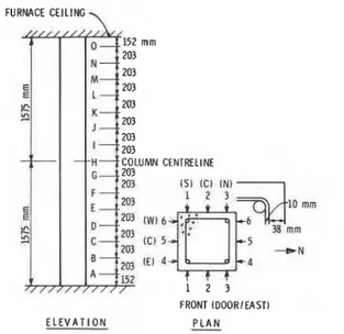
P r i o r t o t h e s t a r t of t h e f i r e t e s t , o v e r 90 p u l s e v e l o c i t y measurements were made through t h e c r o s s - s e c t i o n a t v a r i o u s loca- t i o n s a l o n g a v e r t i c a l p r o f i l e of t h e column. A l a y o u t of loca- t i o n s of t h e p u l s e v e l o c i t y measurements is presented i n Fig. 9.
Pulse v e l o c i t y measurements were a l s o made on companion 152 x 305 mm c o n c r e t e c y l i n d e r s of Column A and Column
B.
Thecylinders were fabricated at the time the columns were cast, and
then maintained at curing and storage conditions identical to those
of the columns. The pulse velocity measurements were made along
both the transverse and the longitudinal axis of the cylinders.
The cylinders were subsequently tested for compressive strength on
the day of the fire test.
Approximately 20 hours after the start of the fire test, pulse
velocity measurements were attempted at each of the test grid
locations identified in Fig. 9. At approximately 25 hours after
the start of the test, a region near mid-height of the column,
between Elevations F and G, was chipped to a depth of 1 to 3 in.
(25 to 75
mm)to remove loose, delaminated material. Chipping was
performed with hand tools. The resulting exposed shape of the
column was nearly round, as shown in Fig. 10. Pulse velocity
measurements were also made through the column in the region.
RESULTS AND DISCUSSION
Column Temperatures
Previous studies
[I],
in which several columns were tested,
showed that the mathematical model used for the calculation of
temperatures in siliceous concrete columns during fire exposure
gives reasonably accurate predictions. In general, predicted
temperatures were slightly higher than those measured, probably
because of conservative assumptions for the mechanism of heat
transfer from the furnace to the column.
The columns tested in the present study were made from the
same siliceous aggregate concrete. Using the same procedure and
thermal properties described in Reference 1, the temperature
history of the columns was calculated. There was again good
agreement between the calculated and the measured temperature
curves. Figures 11 and 12 present measured and calculated
temperatures of the concrete as a function of time for various
depths along the centerline of the column.
Ultrasonic Test Method
The use of ultrasonic test methods to evaluate material prop-
erties and defects in concrete is widespread
[ 8 ] .These techniques
are based on detecting changes in amplitude, phase, and direction
of mechanical waves as they propagate through a concrete member.
Changes in wave characteristics generally indicate a corresponding
change in internal structural make-up of the concrete.
Pulse velocity measurements made prior to exposure to fire
ranged from 4360 to 4665 m/s over the height of Columns A and
B.
The average measured reading was 4510 and 4560 m/s for Columns A
and B, respectively.
Results of pulse velocity tests and corresponding compressive
strengths for 152
x305 mm concrete control cylinders are presented
in Table 1.
TABLE 1 Average measured pulse velocity and compressive strength
for 152
x305
mmcompanion cylinders
Average
Compressive
Cylinder
Pulse Velocity
Strength
Column
No.
(m/s
1
(MPa
1
A
1
4570
37.7
A
2
4600
39.0
A
3
4615
40.0
B
1
4665
42.1
Relationships between pulse velocity and compressive strength
as determined by tests of cylindrical specimens have been compiled
by many investigators. It is important to realize, however, that
these relationships can vary significantly between concrete mixes,
due to differences in aggregates, waterlcement ratios, air content,
moisture content, and density. Plots of pulse velocity versus
compressive strength from references 9 and 10 are presented as
Figs. 13 and 14, respectively. Figure 14 additionally presents a
curve identifying "fire damaged" concrete. Due to dehydration,
matrix restructuring, and micro cracking, there is a significant
decrease in measured pulse velocities for a given compressive
strength for "fire damaged" concrete compared to "undamaged"
material.
The relationship between residual compressive strength and
temperature exposure for siliceous concretes is presented in
Fig. 15. This plot, from Reference 4, indicates an approximate
residual strength of 70, 50, and 20% of original for concrete
exposed to 300, 500, and 700°C, respectively.
Calculations were performed to predict pulse velocity values
for Columns A and B exposed to a one-hour and a two-hour fire,
respectively. The following sequence was employed:
1.
Maximum internal temperatures at various distances from the
exposed face were derived from recorded values.
2.
Measured temperatures were related to anticipated strength for
each zone of temperature exposure within the column, based on
data presented in Fig. 15.
3.
Strength values for each zone of temperature exposure within
the column were related to anticipated pulse velocity values
based on data presented in Figs. 13 and 14.
4.
Utilizing the "total transit time" computational approach, in-
dividual pulse velocity values were combined for each tempera-
ture zone to calculate total, through-section pulse velocities.
P o s t - f i r e v e l o c i t y values c a l c u l a t e d u t i l i z i n g t h e above approach ranged from 1500-2000 m / s f o r Column A and from
1100-1500 m / s f o r Column B. These r e s u l t s compare favourably t o a c t u a l measured v a l u e s of 1200-2000 m / s f o r Column A and
1000-1600 m / s f o r Column
B.
Axial Deformation and S t r e n g t h
Deformation The a x i a l deformations measured d u r i n g t h e t e s t s and t h e c a l c u l a t e d deformations a r e shown f o r Column A i n Fig. 16 and f o r Column B i n Fig. 17. Up t o a t e s t time of f o u r h o u r s , t h e r e i s good agreement between c a l c u l a t e d and measured
deformations. A f t e r t h i s time, t h e d i f f e r e n c e s between c a l c u l a t e d and measured deformations become considerable.
A good agreement between c a l c u l a t e d and measured deformations was a l s o found i n e a r l i e r t e s t s on r e i n f o r c e d c o n c r e t e columns, which were exposed t o f i r e u n t i l t h e column f a i l e d [ I ] . These t e s t s g e n e r a l l y l a s t e d from two t o f i v e hours and d i d not i n c l u d e a c o o l i n g period. The good agreement f o r t e s t s without a c o o l i n g period and f o r t h e p r e s e n t t e s t s i n t h e f i r s t few hours may be a t t r i b u t e d t o t h e f a c t t h a t , f o r r i s i n g temperatures and s t r a i n s of t h e c o n c r e t e and s t e e l , t h e e f f e c t of c r e e p i s included i n t h e s t r e s s - s t r a i n r e l a t i o n s used i n t h e mathematical model. Because of i n s u f f i c i e n t d a t a and complexity of t h e model, t h e e f f e c t of c r e e p i s n o t included i n t h e s t r e s s - s t r a i n r e l a t i o n s f o r d e c r e a s i n g temperatures and s t r a i n s of t h e c o n c r e t e and s t e e l . It i s l i k e l y t h a t t h i s , and shrinkage of t h e c o n c r e t e , a r e t h e main r e a s o n s f o r t h e c o n s i d e r a b l e d i f f e r e n c e between c a l c u l a t e d and measured
deformations a f t e r about f o u r hours.
S t r e n g t h The c a l c u l a t e d r e s i d u a l a x i a l s t r e n g t h of Column A
was 1725 kN and of Column B, 2470 kN. The s t r e n g t h s measured a f t e r c o o l i n g of t h e columns t o n e a r ambient temperatures, were 1987 kN f o r Column A and 2671 kN f o r Column B. Calculated s t r e n g t h s a r e about t e n percent lower t h a n t h o s e measured.
F a c t o r s t h a t may have c o n t r i b u t e d t o t h e d i f f e r e n c e s i n c l u d e t h e somewhat c o n s e r v a t i v e p r e d i c t i o n of column temperatures and n e g l e c t of c r e e p i n t h e c o o l i n g period. Implied i n t h i s r e l a t i o n i s t h e assumption t h a t t h e r e s i d u a l s t r e n g t h of t h e c o n c r e t e i s only a f u n c t i o n of t h e maximum temperature a t t a i n e d by t h e
concrete. It i s known t h a t t h e r e s i d u a l s t r e n g t h i s t o some e x t e n t a f f e c t e d by t h e l o a d on t h e c o n c r e t e d u r i n g heating. S t u d i e s
[4,11,12] showed t h a t t h e r e s i d u a l s t r e n g t h of c o n c r e t e specimens heated under s t r e s s was h i g h e r t h a n t h a t of specimens h e a t e d unstressed. Above a c r i t i c a l s t r e s s of about one-third of t h e compressive s t r e n g t h of t h e c o n c r e t e , however, t h e r e s i d u a l s t r e n g t h was no longer a f f e c t e d by t h e s t r e s s .
The n e g l e c t of t h e i n f l u e n c e of c r e e p and load i n t h e
c a l c u l a t i o n s i s expected t o r e s u l t i n a lower c a l c u l a t e d r e s i d u a l s t r e n g t h . It appears, however, t h a t t h e n e g l e c t of t h e i n f l u e n c e
of t h e s e f a c t o r s does not i n t r o d u c e l a r g e e r r o r s . Thus t h e r e s u l t s suggest t h a t i t i s j u s t i f i e d t o c o n s i d e r t h e r e s i d u a l s t r e n g t h of a concrete column t h a t has been exposed t o f i r e a s p r i n c i p a l l y
dependent on t h e maximum temperatures a t t a i n e d i n t h e concrete. In Figs. 18 and 19, c a l c u l a t e d maximum temperatures reached a t v a r i o u s depths i n t h e column a r e shown, a s w e l l a s t h e r e s i d u a l s t r e n g t h of t h e c o n c r e t e a t v a r i o u s depths a f t e r cooling. Figure 18 shows t h e temperature and s t r e n g t h d i s t r i b u t i o n f o r Column A, which was exposed f o r one hour t o f i r e , and Fig. 19 f o r Column B, which was exposed t o f i r e f o r two hours.
In t h e s e f i g u r e s a l s o t h e p r o f i l e s of t h e s e c t i o n s a r e shown a f t e r f u r t h e r chipping off of t h e weaker concrete with handtools a few weeks a f t e r t h e t e s t . The p r o f i l e s a r e r a t h e r i r r e g u l a r , w i t h most of t h e c o n c r e t e coming off a t t h e corners. The c o n c r e t e a t t h e c o r n e r s s e p a r a t e d from t h e column along v e r t i c a l cracks and came off r a t h e r e a s i l y i n e s s e n t i a l l y triangular-shaped pieces. The cracks were formed a f t e r t h e exposure t o f i r e , and can be a t t r i b u t e d t o t h e f a c t t h a t t h e i n n e r p a r t of t h e column was s t i l l i n c r e a s i n g i n temperature, whereas t h e o u t e r p a r t was c o o l i n g s u b s t a n t i a l l y .
A comparison between t h e p r o f i l e s of t h e remaining c o n c r e t e s e c t i o n s and t h e c a l c u l a t e d isotherms i n d i c a t e s t h a t a c a l c u l a t e d maximum c o n c r e t e temperature of about 550°C i s a reasonable l i m i t a t which t h e concrete possesses s i g n i f i c a n t r e s i d u a l s t r e n g t h . Because c a l c u l a t e d temperatures a r e about t e n percent c o n s e r v a t i v e , t h e a c t u a l temperature a t t h e l o c a t i o n s where t h i s l i m i t i n g
temperature i s reached, i s about 500°C. A t t h i s temperature t h e r e s i d u a l s t r e n g t h of t h e c o n c r e t e , immediately a f t e r cooling down is s t i l l about f i f t y percent of t h e o r i g i n a l s t r e n g t h . A f t e r t h i s , t h e s t r e n g t h reduces somewhat w i t h time f o r s e v e r a l days [4,13-151 but t h e c o n c r e t e w i l l l a t e r r e h y d r a t e and g r a d u a l l y r e g a i n most of i t s o r i g i n a l s t r e n g t h (Fig. 20).
CONCLUSIONS
Various methods can be used t o a s s e s s t h e r e s i d u a l s t r e n g t h of fire-exposed r e i n f o r c e d concrete columns. In t h i s study t h e use of a mathematical model, an u l t r a s o n i c p u l s e t e s t method and a load t e s t method were i n v e s t i g a t e d . The r e s u l t s of t h e study i n d i c a t e t h a t :
1. The column temperatures p r e d i c t e d by t h e model a r e i n good agreement with those measured, although t h e p r e d i c t e d temperatures a r e somewhat conservative.
2. The a x i a l deformations p r e d i c t e d by t h e model a r e f a i r l y a c c u r a t e f o r t h e f i r s t few hours, but d e v i a t e from t h o s e measured i n t h e c o o l i n g period. The d e v i a t i o n can be
a t t r i b u t e d t o c r e e p , which i s taken i n t o account i n t h e model only f o r t h e period of r i s i n g column temperatures. The creep
d i d n o t s i g n i f i c a n t l y a f f e c t t h e r e s i d u a l s t r e n g t h of t h e column.
3. P u l s e v e l o c i t y measured by t h e u l t r a s o n i c test method
c o r r e l a t e d w e l l w i t h t h e r e s i d u a l s t r e n g t h and q u a l i t y of t h e fire-damaged c o n c r e t e .
4. C a l c u l a t e d r e s i d u a l s t r e n g t h s of t h e columns a r e about t e n p e r c e n t lower t h a n t h o s e measured. I n t h e l i g h t of t h e complexity of r e s i d u a l s t r e n g t h e v a l u a t i o n , t h e agreement between t h e c a l c u l a t e d and measured s t r e n g t h s c a n b e r e g a r d e d a s s a t i s f a c t o r y .
I n summary, u s i n g t h e c a l c u l a t i o n p r o c e d u r e and t h e method of measuring p u l s e v e l o c i t y d e s c r i b e d i n t h i s s t u d y , t h e r e s i d u a l s t r e n g t h of c o n c r e t e columns c a n be a s s e s s e d w i t h a n a c c u r a c y t h a t i s s u f f i c i e n t f o r p r a c t i c a l purposes.
REFERENCES
1. L i e , T.T., Lin, T.D., A l l e n , D.E. and Abrams, M.S., F i r e R e s i s t a n c e of R e i n f o r c e d Concrete Columns, N a t i o n a l Research Council Canada, D i v i s i o n of B u i l d i n g Research, DBR Paper 1166, NRCC 23065, Ottawa, 1984.
2. Standard Methods of F i r e T e s t s of B u i l d i n g C o n s t r u c t i o n and M a t e r i a l s , ANSI/ASTM E119-83, American S o c i e t y f o r T e s t i n g and M a t e r i a l s , P h i l a d e l p h i a , 1983.
3. F i r e - r e s i s t a n c e T e s t s
-
Elements of B u i l d i n g C o n s t r u c t i o n , I n t e r n a t i o n a l S t a n d a r d ISO-834, Geneva, 1975.4. Abrams, M.S., Compressive S t r e n g t h of Concrete a t Temperatures t o 1600 F, American C o n c r e t e I n s t i t u t e , S p e c i a l P u b l i c a t i o n SP-25, Temperature and Concrete, D e t r o i t , pp. 33-58.
5. Assessment of F i r e d a m a g e d Concrete S t r u c t u r e s and R e p a i r by Gunnite, Concrete S o c i e t y T e c h n i c a l Report No. 15, The Concrete S o c i e t y , London, 1978.
6. L i e , T.T., New F a c i l i t y t o Determine F i r e R e s i s t a n c e of
Columns, Canadian J o u r n a l of C i v i l E n g i n e e r i n g , Vol. 7, No. 3, 1980.
7. James E l e c t r o n i c s , Inc., " I n s t r u c t i o n Manual f o r Model C-4899 V-Meter", Manual No. F-0062, Chicago, May 1977.
8. Hanson, N.W., Rowe, T.J., A n s t e d t , D., and Corley, W.G.,
V i b r a t i o n Techniques f o r E v a l u a t i o n of D e f e c t s i n Concrete, Vol. 52, P r o d u c t i v e A p p l i c a t i o n s of Mechanical V i b r a t i o n s , Applied Mechanics D i v i s i o n (ASME), New York, 1982, p. 107. 9. Rowe, T.J., E v a l u a t i o n of Concrete i n Columns a t t h e P a r i s h
Tower Company (Mission, Kansas 6620 1)
,
submitted by Construction Technology L a b o r a t o r i e s , a d i v i s i o n of t h e P o r t l a n d Cement A s s o c i a t i o n , Sept., 1981.10. Watkeys, D.G., N o n d e s t r u c t i v e T e s t i n g of Concrete Subject t o F i r e Attack, M.Sc. (Eng.) Thesis, University of London, UK,
1955.
11. Malhotra, H.L., The E f f e c t of Temperature on t h e Compressive S t r e n g t h of Concrete, Magazine of Concrete Research, Vol. 8, No. 23, 1956.
12. Weigler, H., and F i s h e r , R., Beton b e i Temperaturen von 100 C
b i s 750 C, Beton H e r s t e l l u n g Verwendung, V. 18, No. 2, 1968. 13. Zoldners, N.G., E f f e c t of High Temperatures on Concretes
I n c o r p o r a t i n g D i f f e r e n t Aggregates, Mines Branch Research Report No. 64, Department of Mines and Technical Surveys, Ottawa, 1960.
14. Weigler, H., and F i s h e r , R., E f f e c t of Temperatures above 100 C on t h e Compressive S t r e n g t h of Cement Mortar, Behaviour of Concrete a t High Temperatures, B u l l e t i n 164, Deutscher Ausschuss f u r S t a h l b e t o n , 1964.
15. Harada, T., Research on F i r e Proof of Concrete and Reinforced Concrete C o n s t r u c t i o n , Tokyo I n s t i t u t e of Technology, 1961.
F i g . 1-Temperature o f e n v i r o n m e n t as a f u n c t i o n o f t i m e d u r i n g a n d a f t e r f i r e f o r v a r i o u s d u r a t i o n s ( t h ) o f t h e h e a t i n g p e r i o d
S T R A I N . c s
F i g . 2 - S t r e s s - s t r a i n c u r v e s f o r t h e r e i n f o r c i n g s t e e l a t v a r i o u s t e m p e r a t u r e s ( y i e l d s t r e n g t h =
443
MPa)S T R A I N . E
Fig. 4-Stress-strain curves for concrete at various temperatures (compressive strength = 35 MPa)
I
6 0 0 5 0 0 400 I VI- 300 0 0. 01 0. 02 0. 03 0. 04 0. 05 S T R A I N . E ,Fig. 3-Stress-strain relationship for steel after decrease of strain
I I I I
-
-
-
-
T = 40OCC-
--
r WITH DECREASE O F S T R A I N-
0 1 I I IS T R A I N , E c F i g . 5 - S t r e s s - s t r a i n r e l a t i o n s h i p f o r c o n c r e t e a f t e r d e c r e a s e of s t r a i n TEMPERATURE, "C F i g . 6-Residual s t r e n g t h o f s i l i c e o u s c o n c r e t e a f t e r c o o l i n g a s a f u n c t i o n of t h e t e m p e r a t u r e a t t a i n e d by t h e c o n c r e t e
[4,5]
/4B mm COVER TO MAIN REINFORCING BAR
u
305 mm
533 x 533 x 25 mm
THICK STEEL PLATE 7
Fig. 7-Test column and location of reinforcing bars
TRANSMIllING RECEIVING
FURNACE CEILING
\
CENTRILINE
FRONT (DOORIEAST) E L E V A T I O N
-
P L A NFig. 9-Location of pulse velocity measurements
1 SOUTH NORTH 4 DIRECTION THICKNESS OF CONCRETE mrn E - W 292 N - S 279 SE - NW 276 N€ - SW 287 1 - 1 307 2 - 2 286 3 - 3 285 4 - 4 286 SE BAR - M BAR 200 SW BAR - SE BAR 201 NW BAR
-
SW BAR 199 NE BAR - NW BAR 192-
CALCULATED---
M E A S U R E D 200'
25 m m D E P T H 0 a 100 f. W rr 0 64 m m DEPTH T I M E , m i n F i g . 11-Temperature o f c o n c r e t e a s a f u n c t i o n o f t i m e f o r v a r i o u s d e p t h s a l o n g c e n t e r l i n e o f column A ( f i r e e x p o s u r e t i m e : 1 h o u r ) 0 0 200 400 600 800 1WO 1200 1400 1600 T I M E , m i n CALCULATED F i g . 12-Temperature o f c o n c r e t e a s a f u n c t i o n o f t i m e f o r v a r i o u s d e p t h s a l o n g c e n t e r l i n e o f ColumnB
( f i r e e x p o s u r e t i m e : 2 h o u r s )2 0 0 0 1 t I I I I
1
6 0 5 0 4 0 3 0 20 10 0
C O M P R E S S I V E S T R E N G T H . M P a
Fig. 13-Pulse velocity-compressive strength relationship
[ 8 ]C O M P R E S S I V E S T R E N G T H . M P a
125 I I I I I
-
-
-
L1: l DUAL STRENGTH 0 --
*\
a I I I I I I 1 0 100 200 300 400 500 6 0 0 700 800 TEMPERATURE. 'CFig. 15-Residual strength and modulus relation
[ 4 ]
12 I I I I I I I 1 0
-
CALCULATED-
----
MEASURED-
-
W o - 6-
2 - 8-
4- - 1 0-
X < - 1 2-
I - 1 4 - 16 I I L I I I f 0 200 4 0 0 6 0 0 8 0 0 1000 1200 1400 1600 T I M E , minFig. 16-Axial deformation as a function of time (fire exposure time:
1
hour, Column A)-.
--_
---__
- 2 6 - 2 8 CALCULATED---
M E A S U R E D - 3 A T I M E , m i nFig. 17-Axial deformation as a function of time (fire exposure
time:
2
hours, Column
B)
MAXIMUM RESIDUAL STRENGTH TEMPERATURE DEPTH, (FRACTION OF REACHED. "C mm ORIGINAL STRENGTHI
4
t
h
I
' ~ P R O F I L E OF SECTION AFTER REMOVAL OF WEAKER CONCRETEFig. 18-Calculated maximum temperatures reached at various depths
during heating and cooling period and residual strength at various
depths after cooling; profile of section after weaker concrete has
been removed (fire exposure time: 1 hour, Column
A)
MAXIMUM RESIDUAL STRENGTH TEMPERATURE DEPTH, (FRACTION OF REACHED, "C mm ORIGINAL STRENGTH)
4
+
+
i
PROFILE OF SECTION AFTER REMOVAL OF WEAKER CONCRETEFig. 19-Calculated maximum temperatures reached at various depths during heating and cooling period and residual strength at various depths after cooling; profile of section after weaker concrete has been removed (fire exposure time: 2 hours, Column
B)
" 0 1 2 3 4 5 6 7 8 9 1 0 1 1 1 2
T I M E , m o n t h s
Fig. 20-Natural recovery of compressive strength of concrete, heated at various temperatures [ 1 2 ]


![Fig. 13-Pulse velocity-compressive strength relationship [ 8 ]](https://thumb-eu.123doks.com/thumbv2/123doknet/14294352.493100/22.619.150.471.80.368/fig-pulse-velocity-compressive-strength-relationship.webp)
![Fig. 15-Residual strength and modulus relation [ 4 ]](https://thumb-eu.123doks.com/thumbv2/123doknet/14294352.493100/23.619.163.511.69.289/fig-residual-strength-modulus-relation.webp)

![Fig. 20-Natural recovery of compressive strength of concrete, heated at various temperatures [ 1 2 ]](https://thumb-eu.123doks.com/thumbv2/123doknet/14294352.493100/25.615.165.495.555.861/natural-recovery-compressive-strength-concrete-heated-various-temperatures.webp)
