READ THESE TERMS AND CONDITIONS CAREFULLY BEFORE USING THIS WEBSITE. https://nrc-publications.canada.ca/eng/copyright
Vous avez des questions? Nous pouvons vous aider. Pour communiquer directement avec un auteur, consultez la première page de la revue dans laquelle son article a été publié afin de trouver ses coordonnées. Si vous n’arrivez pas à les repérer, communiquez avec nous à [email protected].
Questions? Contact the NRC Publications Archive team at
[email protected]. If you wish to email the authors directly, please see the first page of the publication for their contact information.
NRC Publications Archive
Archives des publications du CNRC
This publication could be one of several versions: author’s original, accepted manuscript or the publisher’s version. / La version de cette publication peut être l’une des suivantes : la version prépublication de l’auteur, la version acceptée du manuscrit ou la version de l’éditeur.
Access and use of this website and the material on it are subject to the Terms and Conditions set forth at
Temperature controlled humid storage room
Bozozuk, M.
https://publications-cnrc.canada.ca/fra/droits
L’accès à ce site Web et l’utilisation de son contenu sont assujettis aux conditions présentées dans le site LISEZ CES CONDITIONS ATTENTIVEMENT AVANT D’UTILISER CE SITE WEB.
NRC Publications Record / Notice d'Archives des publications de CNRC:
https://nrc-publications.canada.ca/eng/view/object/?id=feea03d7-0f79-4358-ba38-ae37b3e9b0c2 https://publications-cnrc.canada.ca/fra/voir/objet/?id=feea03d7-0f79-4358-ba38-ae37b3e9b0c2TH1
i a l Research Council of Canada
--
N
:
noc . 2
lil national de recherches du Canada
BLDG-
TEMPERATURE CONTROLLED HUMID STORAGE ROOM
byMichael $ozozuk
Reprinted from
ASTM Special Technical Publication 599
June 19
76
R U ~ L ~ ~ N G
R F ~ F A R C M 713p.
Ii
I Y I 1I
II
-_
N LT R E S E ~ R C M CC\ NcIL ;_
_*--+----.-
-
G*li55
DBR Paper No. 680
Division of Building Research
APrice 25 cents
OTTAWA
NRCC 15336
Authorized Reprint from Special Technical Publication 599
Copyright
American Society for Testing and Materials 1916 Race Street, Philadelphia. Pa. 19103
1976
Michael
Bozozuk'
Temperature-Controlled
Humid
Storage Room
REFERENCE: Bozozuk. Michael, "Temperature-ControUed Humid Storage Room,"
Soil Specmen Preparation for Laboratory Testing, ASTM STP 599, American So-
ciety for Testing and Materials, 1976, pp. 113-125.
ABSTRACT: The design of a soil sample storage room that has been in operation since 1954 is described. The room provides a storage environment with a constant temperature of 55 OF and relative humidities of 90 to 97 percent. It is of wood frame construction, lined with copper sheeting, forming a watertight interior. The desired temperature and humidities are obtained by running water down the walls of the room and circulating it through a heat exchanger. The preparation of samples for storage and the effect of storage times on soils are discussed.
KEY WORDS: soils, design, storage room, constant temperature, humidity, samples, storage time
The purpose of a storage room for soils is to retain soil specimens in their original condition at time of sampling until testing can be under- taken. The functional requirements for such facilities will depend upon the nature and quality of the samples to be stored, as well as the use to be made of them. Granular soils obtained for grain size or compaction tests can be kept in ordinary burlap sacks and stored almost any place for years, even in an unheated shack. On the other hand, high quality undis- turbed samples of sensitive marine clays, obtained for consolidation, undrained triaxial strength, or other special engineering tests, require careful handling and ideal storage conditions. These samples should be wrapped, waxed, labelled, and stored properly, free of shocks or vibra- tions, in a humid environment at a constant temperature near that which prevailed in the ground at the time of sampling.
Unless these storage requirements are met, high quality undisturbed soils will deteriorate, and the results of the special engineering tests would be questionable. The storing of soils in a warm, humid environment is conducive to high rates of oxidation causing chemical changes in the soil,
Research officer, Geotechnical Section, Division of Building Research, National Re- search Council of Canada, Ottawa, Ont., Canada.
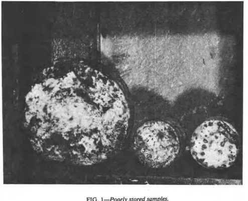
deterioration of the sealing wax, and formation of water blisters (Fig. l), and sometimes breeds bacteria that feed upon the soils or the wax. High temperatures permit dissolved gases in saturated clays to come out of solution, causing expansion and deterioration of the. soil skeleton. If stored in a dry and warm environment, soil moisture may escape, causing
FIG. 1 -Poorly stored samples.
the soils to shrink; on the other hand, samples stored submerged in water containers may absorb water and swell. Consequently, the clays could change both physically and chemically so that they would no longer exhibit the engineering properties of the
in
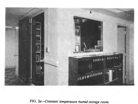
situ soil they are supposed to represent.In 1954, the Division of Building Research, National Research Council of Canada, designed and constructed a temperature-controlled humid storage room (Fig. 2), to reduce or minimize the effects of improper storage; it has operated continuously since then. The room is approxi- mately 13 ft long, 6% ft wide, and 9 ft high. A removable wooden floor provides
a
relatively dry walking area and supports the storage shelves and working table. This paper discusses the design of the room, the han-dling and preparation of samples for storage, and the effect that long stor- age times can have on engheering properties.
BOZOZUK ON TEMPERATURE CONTROLLED HUMID STORAGE ROOM 115
FIG. 2a--Cotwant temperatupe humid storage room.
Design I
The storage room was designed as a necessary accessory to laboratory soil testing facilities. Its purpose is to keep the soil samples in the best possible condition, that is, to bridge the period from the time they are obtained in the field until they are tested and to provide a conditioned environment for performing certain special engineering tests, when re-
quired. )
The principle of operation is as fo~~owb. Water is directed to flow down the inside walls of the room to the floor, where it is ponded. Natural evaporation from the wetted walls and the reservoir that covers the entire floor area provides relative humidities from 90 to 97 percent. The temperature control is obtained by circulating the ponded water through a heat exchanger located outside the
rooml
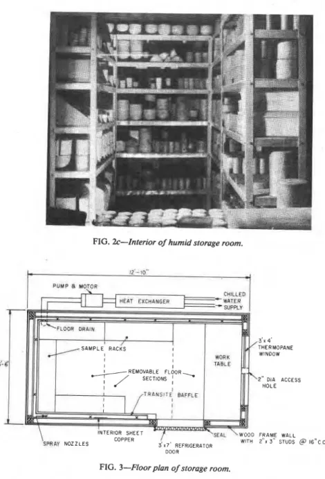
After it is cooled, it is pumped back to the top of the room, where it is directed against the walls through nozzles to complete the flow cycle. Any heat gain through the walls is picked up by the flowing water and dispelled through the heat exchanger.The storage room is essentially a copper tank enclosed in an insulated wood frame. A plan view (Fig. 3) shows the layout of the sample racks and worktable, relative to the door and window. It was constructed on 2 by 2-in. wood sleepers laid on the concrete floor of the laboratory. Set at 12 in. centers and running parallel to the length of the room, they were covered with ?A-in.-thick plywood and nailed together (Fig. 4). The
FIG. 2b-Mechancalpkmt: (a) chilled liquid and (b) heat exchanger.
purpose of the sleepers was to provide an air space and ventilation for the floor and adequate support for the superstructure, in case it had to be moved. The plywood was then covered with a vapor barrier that projected about 2 in. beyond the perimeter.
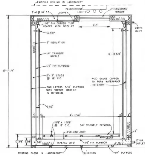
To facilitate circulation of the ponded water, the floor was sloped 1 in. to the drain located at the back of the room by tapering the 2 by 6-in. floor joists. They were placed across the sleepers to form the floor of the room. The wall frames, made of 2 by 3-in. studs, were erected on the joists, which, in turn, supported the frame roof made up of 2 by 4-in. joists. All joists and studs were placed at 16 in. centers whenever possible. The spaces between the studs and joists in the floor and ceiling were insulated with 2-in.-thick mineral wool insulation. The exterior of the room was first sheathed with a layer of 5/16-in. plywood, then covered completely with a vapor barrier that overlapped at the ends and corners. It was, in turn, protected with a second layer of 5/16-in. plywood.
The walls, floor, and ceiling inside the room were covered with %-in.- thick fir plywood. Finally, it was covered completely with 20-gage copper sheeting to form a watertight interior.
BOZOZUK ON TEMPERATURE CONTROLLED HUMID STORAGE ROOM 117
FIG. 2c-Interior of humid storage room.
61
WITH 2"" 3" STUDS @ DOOR
FIG. 3-Floor plan of storage room.
Two
thennopane windows were provided for lighting. A 3 by 4-itwindow installed at one end of the room aIlowed ordinary light from
the laboratory to illuminate the worktable (Fig. 3). A second 2 by 4-ft
window was installed in the ceiling to permit artificial lighting of the room, using a fluorescent ceiling lamp suspended above it (Figure 4). For
FIG. 4-Design section of storage room.
safety reasons, no electric outlets or fixtures were permitted inside the room. If power is required, it is brought in through the 2-in. diameter access or service hole through the wall, 5 in. from the ceiling above the window (Fig. 3). The hole is left open to dissipate the air cushion effect every time the door was opened or closed.
A 3 by 7-ft refrigerator door with a . two-way latch, insulated and covered with sheet copper, was installed on the outside to close against a rubber seal placed around the doorway.
Three removable floor sections were constructed to provide the walking area and support for the racks and table above the reservoir (Fig. 3). These consisted of %-in. sylvaply plywood sections nailed to 2 by 2-in. cedar sleepers, which, in turn, were nailed to 2-in.-thick tapered cedar
BOZOZUK ON TEMPERATURE CONTROLLED HUMID STORAGE ROOM 119
levelling joists (Fig. 4). The removable floor facilitates maintenance when required. A 5 in. clearance was provided, adjacent to the sprayed walls (Figs. 3,4), to ensure an adequate circulation of air under the floor. Closed Flow Conditioning System
The desired storage temperature and relative humidity are obtained by continuously circulating the ponded water from the reservoir through a heat exchanger and back into the top of the room, where it is directed to flow down the walls. This is achieved by pumping the preconditioned water into a copper tube header, fastened to the ceiling about '/2 in. away from the walls, and covering most of the room perimeter (Fig. 3).
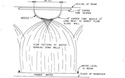
Originally, the header was fitted with eleven flat atomizer jets spaced relatively uniformly, but this mixed the air and water to such an extent that it created fog. Any objects placed in the room collected water im- mediately. Even beakers filled up within a short time. Such an environ- ment was satisfactory for storing and curing concrete specimens but was not considered satisfactory for soil samples. Consequently, the atomizer jets were replaced with 10 in. lengths of !A-in.-diameter copper tubing. It was possible, by bending the tubing to direct the flow along the walls, to create the flow pattern illustrated in Fig. 5, and to wet the walls below
24" C C.
CEILING OF ROOM
TUBE HEPDER
WATER LEVEL
PONDED WATER
FIG. 5-flow pattern of water along walls of storage room.
the header completely. A %-in. transite (asbestos) baffle, installed in 4-ft-wide sections and set 2% in. away from the walls, prevented splash- ing of the interior (Fig. 4). It also increased the wetted surface area from which water evaporated into the room. The bottom of the baffle was
kept about 2 in. above the surface of the ponded water to ensure proper circulation of air.
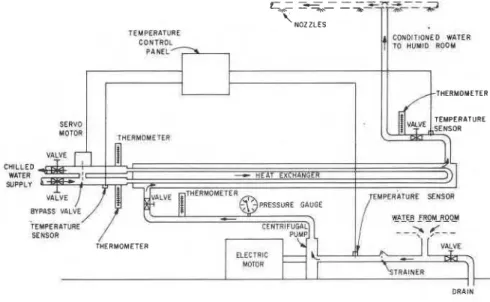
The storage room requires about 75 Imperial gallons of water to create a pond 1 M in. deep at the shallow end. Slimacide V-10, with a pine root oil base, is added to the circulating water to prevent bacterial growth. The water is pumped from the reservoir, through a strainer, to the heat exchanger, as shown in Fig. 6, where it is cooled, then back to the room
'
NOZZLES1 1
TEMPERATURE CONTROL
FIG. 6-Conditioning equipment and controls.
at a rate of 15 Imperial gal/min, under a pressure of 16 psi. A single phase 110-V 60-cycle 3450-rpm M-hp motor powers the centrifugal pump. The temperature of the chilled water supply feeding the heat ex- changer is about 41 OF; it is exhausted at about 47°F.
The temperature of the storage room is regulated by the control panel and three temperature sensors installed at the locations shown. The panel operates the servo motor diiving the by pass valve mounted on the chilled water supply line, thus controlling the amount of cooling required to maintain a room temperature of 55"F, which is about the mean annual ground temperature in the Ottawa region. Four thermometers, located as shown, provide an easy check on the operation of the system. In assembling the plumbing system, air bleed valves were provided at all high points and drains at all low points. To facilitate maintenance and flushing of the room, it is connected permanently to a floor drain in the laboratory.
BOZOZUK ON TEMPERATURE CONTROLLED HUMID STORAGE ROOM 121
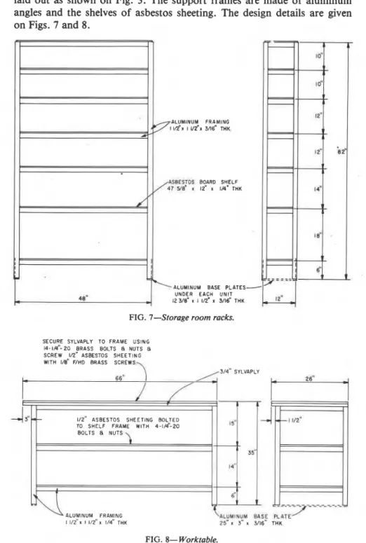
laid out as shown on Fig. 3. The support frames are made of aluminum
angles and the shelves of asbestos sheeting. The design details are given on Figs. 7 and 8.
FIG. 7-Storage room racks.
SECURE SYLVAPLY TO FRAME USING 1 4 - t ~ " - 2 0 BRASS BOLTS NUTS a SCREW 1/2" ASBESTOS SHEETING WITH I'd' WHD BRASS SCREWS
*
'I
3/4" SYLVAPLY
86"
d f
*- 1/2" ASBESTOS SHEETING BOLTEDTO SHELF FRAME WlTH 4-1/4-20 I 5" BOLTS a NUTS 35" 14" ALUMINUM FRAMING 1 1/2"x 1 112" x 1/4" THK L i u r n l u u ~ 25" r: 3" x Bas[ 3/16" THK PLmE' FIG. 8- Worktable.
Handling and Preparation of Samples for Storage
Careful handling and protection of high-quality undisturbed samples start in the field. As soon as the sample tubes are removed from the bore- hole, they are numbered, sealed and capped, and placed in special carry- ing cases lined with styrofoam and foam rubber. Consequently, the samples are protected from extreme temperature changes, shocks, and vibrations until they reach the laboratory.
At the laboratory, they are recorded immediately and placed in the storage room. If the sample tubes are made of stainless steel, the soil cores can be left in them until needed. If rusting or corrosion is a pos- sibility, or if the tubes are needed for continuing the sampling program, the soils should be extruded and waxed for storage.
The cores are extruded vertically, using a hydraulic extruder. They are extruded in lengths of 4 or 8 in. at a time, cut off with a wire saw, covered with thin plastic film and coated by dipping them carefully several times into melted wax. For very weak or soft soils, the cores are wrapped with cheesecloth to provide lateral support as they are extruded, then cut off, wrapped in plastic film, and waxed. The wax used in the laboratory is a Grade 175 microwax (Imperial Oil Co.), that has a congealing temperature of 78°C. Labels are applied and coated with wax before the samples are placed on the storage racks. Block samples are prepared for storage in a similar way, except that the wax is applied by brush.
Effect of Storage Time on Test Results
Grain size analysis and Atterberg limits of sensitive marine clays do not appear to be affected significantly by long periods of storage, even though the samples change color frequently, indicating that some chemical changes have occurred. La Rochelle et a1,2 on the other hand, found that the shear strength of some Champlain clays was reduced after long periods of storage. Similar results were obtained from strength tests performed on marine clays from Canadian Forces Station (CFS) Glou- cester, which had been stored for seven years. The results, summarized in Table 1, show that generally the degree of saturation and wet density decreased, and the water content increased somewhat by extending the storage time from one to seven years. There was also a reduction in shear strength, averaging 11.2 percent and a small decrease in strain at failure.
Some investigator^',^ have found that long storage times reduce the
%a Rochelle, P., Sarrailh, J., Roy, M., and Tavenas, F. A., this publication, pp. 126-146. 'Leonards, G. A. and Altschaeffl, A. G., Journal of Soil Mechanics and Foundations
Division, Vol. 5, Sept. 1964, pp. 133-155.
'Bozozuk, Michael in Sampling of Soil and Rock, ASTM STP 483, American Society for Testing and Materials, 1971, pp. 121-131.
TABLE 1-Effect of storage on triaxial consolidated anisotropically undmined strengths, measured on undisturbed tube samples of marine clay, obtained from CFX Gloucester, Dec. 1967.
Consolidation
Stress, kg/cm2 Tested. Nov. 1968
w. % v. AQ, lb/ft3 kg/cm2 80.7 96.4 0.348 52.1 107.6 0.546 85.3 95.4 0.493 88.7 94.5 0.706 79.1 97.3 0.716 50.0 108.5 0.818 70.5 99.7 0.774 35.6 117.8 0.734 Tested, Dec. 1974 w, % Y, AQ, lb/ft3 kg/cm2 Average Change, %
NOTES-Q '. = in sim vertical effective stress.
o '. = effective confining pressure.
S = degree of saturation at start of test. w = water content at start of tat.
y = wet density at start of test.
6Q = maximum deviator stress at failure. A(o, - o,),.
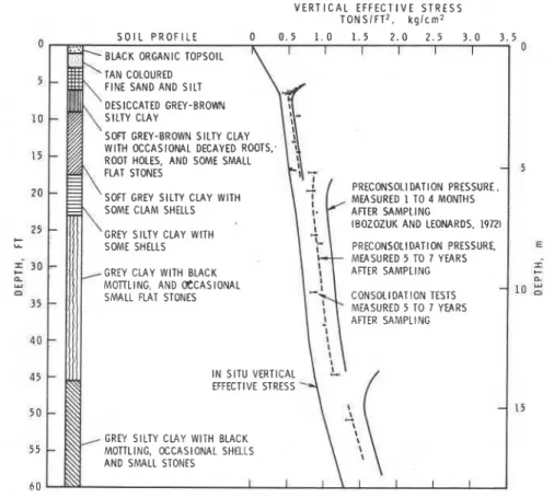
measured preconsolidation pressure, whereas others2 found no effect. To investigate this point further, additional consolidation tests were performed on undisturbed samples of clay from CFS Gloucester that had been stored in the temperature-controlled humid storage room from five to seven years. In Fig. 9, the results are compared with the original tests reported by Bozozuk and Leonards.* The measured preconsolidation
V E R T I C A L E F F E C T I V E STR2ESS T O N S I F T 2 . k g l c m
0 S O I L P R O F I L E 0 0 . 5 1 . 0 1 . 5 2 . 0 2 . 5 3 . 0 3 . 5 0
5 FINE SAND AND SILT
DESICCATED GREY-BROWN
10
SOFI GREY-BROWN SILTY CLAY
1 5 WlTH OCCASIONAL DECAYED ROOTS: ROOT HOLES. AND SOME SMALL
5
20 SOFT GREY SILTY CLAY WITH PRECONSOLI DATION PRESSURE.
MEASURED 1 TO 4 MONTHS SOME CLAM SHELLS ARER SAMPLING
25 lBOZOZUK AND LEONARDS. 1972)
t GREY SILTY CLAY WITH
U- PRECONSOtlDATlOM PRESSURE, E
f 3 0 MEASURED 5 TO 7 YEARS AFlER SAMPLING si
GREY CLAY WITH BLACK c
IIL
ly M O l l t l N G , AND E C A S I O N A L
L
a SMALL FLAT STONES CONSOLlDATlON TESTS 1 0
:
35 MEASURED 5 TO 7 YEARS AFlER SAMPLING 4 0 45 I N SlTU VERTICAL EFFECTIVE STRESS 5 0 15
GREY SILTY CLAY WlTH BLACK 55 MOTTLING, OCCAStONAL SHELLS
AND SMALL STONES
6 0
FIG. 9-Effect of storage time on preconsolidation pressure measured on undisturbed samples obtained from CFS Gloucester.
pressure was reduced only slightly in the lightly overconsolidated clay formation from 6 to 18 ft (1.8 to 5.5 m). Below this depth, the measured overconsolidation pressure of 0.25 kg/cm2 was 40 percent lower than the originally measured value of 0.42 kg/cm2. Below the 50 ft (15.2 m) depth, the reduction was about 35 percent. As the loading schedules in both
5Bozozuk, Michael and Leonards, G. A. in Proceedings, Specialty Conference on
Performance of Earth and Earth-Supported Structures, American Society of Civil Engineers, Purdue University, West Lafayette, Ind., Vol. 1, Part 1, 11-14 June 1972, pp. 229-317.
testing programs were identical and the test specimens were the same size, the observed reduction in preconsolidation pressure must be attributed to storage time.
The evidence concerning the detrimental effects of storage time on the engineering properties of soils is accumulating but is still not entirely conclusive. Detrimental effects, as noted previously, have been observed under the best storage conditions, and it is known that a relaxation of
I
stresses with time may cause changes in soil structure. In planning a soil
I testing program, therefore, consolidation, undrained triaxial strength, and
other special engineering tests should be performed as soon as possible after the samples are obtained. Atterberg limits, grain size analysis, and other classification or index tests may be performed after long periods of storage without affecting the results seriously.
~
SummaryIn 1954, a controlled-temperature humid storage room was designed and constructed in the Geotechnical Laboratory of the Division of Build- ing Research, National Research Council of Canada. The room is a wood frame construction, lined completely with sheet copper on the inside. The desired temperature and humidity are achieved by running water down the walls t o the floor, where it is ponded below a removable floor. Heat gain into the room is removed by pumping the water through a heat exchanger fed by chilled water. The paper discusses the design, the preparation of samples for storage, and the effects that long storage times may have on test results.
Acknowledgments
Thanks are due to K. R. Solvason, Research Officer, Building Services Section, who designed the mechanical plant for the storage room.
This paper is a contribution from the Division of Building Research, National Research Council of Canada and is published with the approval of the Director of the Division.