HAL Id: hal-00502592
https://hal-brgm.archives-ouvertes.fr/hal-00502592
Submitted on 15 Jul 2010HAL is a multi-disciplinary open access archive for the deposit and dissemination of sci-entific research documents, whether they are pub-lished or not. The documents may come from teaching and research institutions in France or abroad, or from public or private research centers.
L’archive ouverte pluridisciplinaire HAL, est destinée au dépôt et à la diffusion de documents scientifiques de niveau recherche, publiés ou non, émanant des établissements d’enseignement et de recherche français ou étrangers, des laboratoires publics ou privés.
CO2 geological storage safety assessment:
methodological developments
Olivier Bouc, Gaël Bellenfant, Didier Dubois, Dominique Guyonnet, Jeremy
Rohmer, Marie Gastine, Frédéric Wertz, Hubert Fabriol
To cite this version:
Olivier Bouc, Gaël Bellenfant, Didier Dubois, Dominique Guyonnet, Jeremy Rohmer, et al.. CO2 geological storage safety assessment: methodological developments. 10th International Probabilistic Safety Assessment & Management Conference, Jun 2010, Seattle, United States. 12 p. �hal-00502592�
CO
2geological storage safety assessment: methodological developments
O. Bouc
a*, G. Bellenfant
a, D. Dubois
b, D. Guyonnet
a, J. Rohmer
a, M. Gastine
a, F.
rtz
a, H. Fabri
aWe
ol
a
BRGM, Orléans, France
b
IRIT, Université Paul Sabatier, Toulouse, France
Abstract: Carbon dioxide capture and geological storage is seen as a promising technology to mitigate greenhouse gas atmospheric emissions. Its wide-scale implementation necessitates demonstrating its safety for humans and the environment. We have developed a generic approach to provide references for safety assessment of CO2 storage. It is composed of a series of simple tools for identifying risk
scenarios, modelling risk events and exposure. It incorporates a rigorous management of uncertainty, distinguishing between variability and knowledge incompleteness. We applied this approach on a case study in the Paris Basin. This demonstrates how it delivers conditions mixing qualitative and quantitative elements for guaranteeing safety. This approach is flexible; it can be used for various sites and with various amounts of data. It can be carried out in a time-efficient manner at various stages of a project. In particular, it provides an operator or an authority with safety indicators in an early phase or for reviewing a risk assessment. Though not a complete risk assessment workflow, it thus partly compensates for the current lack of commonly acknowledged assessment methods or safety standards for CO2 geological storage.
Keywords: CO2 geological storage, risk, uncertainty, hybrid approach.
1. INTRODUCTION
Reducing greenhouse gas anthropogenic emissions to mitigate climate change and ocean acidification requires a portfolio of measures, such as improving energy efficiency and increasing renewable energy production. Carbon dioxide capture and geological storage (CCS) is seen as a decisive technology in this portfolio: its capability to effectively reduce greenhouse gas emissions to the atmosphere in the long term has been validated by the Intergovernmental Panel on Climate Change [1]; the International Energy Agency (IEA) recently evaluated the contribution of CCS to emissions reductions by 2050 to one fifth in order to achieve the most cost-effective stabilisation of greenhouse gas concentrations [2]. From this result, the IEA concludes that the implementation of the technology should reach 100 projects in 2020, and more than 3000 in 2050 representing an amount of 10 GTCO2 stored per year [2].
These figures highlight the number of storage sites that should be operated. Care will be required on all these sites to ensure that the storage is both efficient and safe: safety of CO2 storage is a key issue
for wide scale implementation of the CCS technology [3]. Risk assessment for CO2 storage has been a
research topic so far, as testified by the activity of the IEA GHG Risk Assessment Network ([4], [5]). Neither safety standards nor a commonly acknowledged methodology in this field have emerged. We propose a simple and flexible approach to determine safety criteria for a CO2 geological storage
project, incorporating quantitative and qualitative information related to the site. This approach does not deliver a complete risk assessment; it is thought to supply relevant elements to evaluate safety in a time-efficient manner. It can be run with a limited amount of data and enriched when more knowledge becomes available. Therefore it is useful:
- either at an early stage of a project, for targeting site characterisation at the potentially critical elements,
- or at the licensing stage, providing the competent authority with assessment criteria for reviewing a risk analysis.
Our approach seeks to encompass all the potential risk scenarios, from geomechanical risks to CO2
leakage risks. It is based on simplified modelling to evaluate the potential consequences of these scenarios. It incorporates an uncertainty management framework, whose purpose is to faithfully represent and propagate the uncertainty related to the site properties. The development of this approach has been supported by a case study in the Paris Basin.
2. PURPOSE AND CONCEPT
Safety assessment presents a number of challenges for CO2 geological storage. As an emerging
technology, it can only rely on a limited experience. Few pilot storage projects have been operating so far, the oldest counting about 15 years experience. Enhanced Oil Recovery (EOR) has been running for more than 30 years, with a slightly different scope than CO2 storage though, since usually EOR
was not designed in the purpose of retaining CO2 in the underground. Natural gas seasonal storage
experience also has limited value for CO2 storage risk assessment, due to significant differences in the
fluid properties, in the physico-chemical processes involved and in the time scales for containment. Furthermore, experience gained through all these techniques is relevant for time scales in the order of a few decades. CO2 storage on the contrary aims at containment for a few centuries or millennia.
Safety assessment for CO2 storage therefore requires investigating unusual time scales. Comparisons
with research carried out on nuclear waste deep disposal risks do not seem relevant either, due to the processes involved and the corresponding time scales.
In addition to time scales and limited experience, CO2 storage safety assessment must face variability
between sites, and intrinsic uncertainty surrounding the geological medium. Unlike engineered systems, the storage complex investigated for injecting CO2 cannot be completely depicted. It is a
continuous medium known through punctual and/or indirect measurements. Therefore, though the purpose of site characterisation is to reduce uncertainty as much as possible, risk assessment has to deal with somewhat significant residual uncertainty. Besides, the underground varying from one site to another, lessons learned through one project can be transposed only with care to another.
For all these reasons, combined with the complexity of representing the various phenomena that intervene in the CO2 storage behaviour, it appears impossible to define generic quantitative safety
standards. No quantitative risk assessment methodology has been established so far. In particular, for CO2 geological storage the concept of probabilistic safety assessment must be cautiously considered.
Experience feedback can inform failure probabilities for the engineered components; in our case wells only. Failure probabilities for natural components of the storage complex would be poorly reliable, because of site specificity. At best qualitative probability could be elicited.
Instead of probabilistic safety assessment, we propose an alternative approach combining quantitative and qualitative elements, and consisting in identifying the potentially critical risk scenarios and evaluating their assumed consequences. We want to deduce requirements to prevent the occurrence of these events or guarantee that their magnitude is contained within an acceptable range, as defined by the potential impacts on human health and environmental safety. Such requirements would relate to the properties of the reservoir or other components of the complex (cap rock, wells…), i.e. to characterisation needs, or to injection parameters (pressure, flow rate…), i.e. to operational design. Requirements for monitoring and risk mitigation measures can be inferred then.
We are looking at a framework that would be: - flexible, to be applied and suited to each site;
- simple, in the sense that it should be possible to use it in a time-efficient manner with various levels of knowledge. Thus, an operator in an early phase of its project could employ it to identify critical points and target site investigation accordingly. In a licensing process, the competent authority could in turn use it to screen in the application whether and how major issues were addressed. We therefore rely on simple modelling, promoting analytical or semi-analytical models to the extent possible. In addition to computing time efficiency, simple models allow assessing uncertainty propagation. This is a critical point for risk assessment to represent the level of uncertainty and be able
to identify its sources. Having made the choice of simple modelling, avoiding over-simplifying raises a concern. Meanwhile, in a precautionary approach, conservative assumptions should be preferred in the model. The correct but tricky attitude consists in adopting reasonably conservative assumptions. The approach should deliver requirements to guarantee that the storage of CO2 at the considered site is
safe to human and the environment. These requirements would be quantitative when sufficient data is available. Where too much unknown remains, they will take the form of qualitative statements.
3. RISK SCENARIOS AND MODELS USED
Implementing our approach, where safety requirements are determined according to the impacts that can result from unexpected behaviours, requires performing the following steps, which are not unusual in risk assessment:
- evaluate the expected behaviour (or the range of “normal” behaviours) of CO2 and the storage
complex;
- identify credible risk scenarios, i.e. possible evolutions deviating from this range;
- estimate the potential magnitude of dangerous phenomena resulting from these alternative scenarios;
- assess the corresponding impacts against acceptance criteria (usually defined by regulation). The following paragraphs present the main tools we propose for carrying this out.
3.1. Reservoir flow and pressure
We compute the extent of the CO2 plume in the reservoir with the analytical model developed by
Nordbotten et al. ([6], [7], [8]; see [9]), and the pressure field in the reservoir using the analytical model developed in [10]. These models suppose a plane horizontal reservoir of constant thickness and radial symmetry (no natural brine flow in the aquifer), as well as sharp brine – CO2 interface (capillary
pressure effects are ignored). The flow model delivers the thickness of the CO2 front as a function of
time and distance to the injection well. We extract from there the maximum extent reached by CO2 or
the thickness of the CO2 front at a given point. Note that the flow model is only valid when buoyancy
is not dominant; otherwise it resorts to semi-analytical resolution of a differential equation. Moreover, these models can only be used over the injection period; beyond, numerical models must be applied. 3.2. Risk scenarios identification
In the frame of our research, we employ a risk scenario identification method based on expert workshops, derived from the approach described in [11]. A generic list of 11 risk events has been established ([12]), not restricted to leakage risks, but considering also geomechanical risks for instance. Experts must determine from this list the relevant events in the light of their knowledge of the site and the results of simulations for the expected behaviour.
3.3. Well leakage
CO2 leakage through a well is studied through a sequence of two analytical models, as described in
[13]. At first, CO2 entry into the well is represented by a one-dimension Darcy flow model through the
seals (well casing and cement plugs). Then, under a conservative assumption, we evaluate CO2 rise in
the well seen as a column filled with water. This model thus delivers pessimistic estimates of the CO2
flow rate and rising time out of the well, as a function of overpressure, CO2 front thickness in the
reservoir, and characteristics of the well, especially thickness and permeability of its seals. 3.4. CO2 rise in a porous column
An analytical model of one-dimension Darcy flow through a vertical porous column is employed to assess the case of cap rock sealing deficiency: leakage through a fault or a permeable zone in the cap rock. It delivers the CO2 flow rate and rising time as a function of overpressure in the reservoir and
transport properties of the leakage pathway. A homogeneous column with an equivalent overall permeability can substitute for a column composed of layers with varying permeability.
3.5. Cap rock integrity
Cap rock mechanical integrity failure in the injector’s vicinity is evaluated through the semi-analytical model set up in [14]: a linear regression from a limited number of numerical computations establishes the effective stress as a function of pressure at the basis of the cap rock and a number of site geometrical, mechanical and petrophysical properties. It enables the assessment of the mechanical failure criterion as a function of these parameters, for both the tensile and shear slip failure modes. 3.6. Exposure models and leakage thresholds
Loss of cap rock integrity is a priori considered unacceptable. Regarding CO2 leakage, criteria relate to
their potential impacts. Two main kinds of vulnerable assets are considered here, corresponding to the hypothesis of onshore storage: human health and the environment at ground level; freshwater aquifers. Others would include other underground resources or offshore ecosystems.
3.6.1. Surface exposure
Potential effects of CO2 leakage to the surface on health and the environment depend on the exposure
of the vulnerable assets. Regulatory thresholds exist in many countries to regulate human exposure to CO2 ([1]). In France, these thresholds on CO2 atmospheric content are as follows ([15], [16]):
- 0.5% for occupational exposure (time-weighted 8 hour average); - 5% short-term exposure limit: irreversible effects;
- 10% short-term exposure limit: first lethal effects; - 20% short-term exposure limit: significant lethal effects.
Impacts of elevated CO2 exposure of ecosystems are much less understood, the response of individual
species being highly variable ([17]). It is believed that many air breathing animals have fairly comparable tolerance to CO2 with humans ([18]).
In a precautionary approach, we suggest to adopt the most stringent threshold for human health (0.5%) as acceptable limit at ground level. Alternatively, we could differentiate between acute (5% limit) and prolonged exposure (0.5% time-weighted limit).
These thresholds are expressed in terms of CO2 atmospheric content, while the CO2 leakage models
provide values for flow rates. Therefore a conversion from flow rate to concentration is required. We propose a perhaps excessively conservative computation derived from [19]. The leakage pathway is assumed to open right into a building. The leaking gas flows directly into the building, without any attenuation in the geological layers, neither in the vadose zone nor in the foundations of the edifice. Typical geometrical parameters for a house and ventilation rates are taken from literature relative to exposure to radon ([20]) and to construction work ([21]): for a 250 m3building with a ventilation rate of 0.5 h-1, a simple dilution computation shows that, to remain below 0.5% CO2 in the indoor
atmosphere, it is required to maintain the CO2 flow rate below 0.3 g.s -1
. 3.6.2. CO2 entry into a freshwater aquifer
Changes in freshwater chemistry due to CO2 intrusion following a migration from the storage reservoir
can be studied through reactive transport simulations of an underground source of drinking water. Chemical effects are highly dependent from the site conditions in terms of initial water composition, aquifer mineralogy and hydraulic properties. Reactive transport modelling teaches potential changes in pH and concentration of a number of ions (e.g. nitrates or nitrites) or elements (e.g. lead or iron); the resulting concentrations can then be compared to regulatory quality limits for water consumption, as established in the European Union according to the Directive [22]. However, such modelling to evaluate water quality changes where it is produced is highly site-specific. We have not solved how to
incorporate the study of these impacts in our generic framework. Consequently in the following we focus on surface exposure. Site-specific simulations may nevertheless induce more stringent criteria on leakage rates to guarantee that accidents do not excessively alter water quality.
4. UNCERTAINTY MANAGEMENT
Assessing risk involves taking uncertainties into account, which represents a particular challenge for CO2 geological storage due to significant uncertainty pervading site knowledge. The proper
uncertainty assessment of parameters needs to distinguish between two kinds of uncertainty (e.g. [23]):
- stochastic uncertainty, i.e. variability, related to natural heterogeneity;
- epistemic uncertainty, resulting from imprecision or incompleteness of available information. Stochastic uncertainty can be depicted as an objective uncertainty, since it reflects natural variations. Epistemic uncertainty is subjective in the sense that it refers to the position of the scientist with respect to his study’s object, and can be reduced by further measurements. It seems therefore crucial in a risk assessment process to faithfully represent the genuine knowledge about the system, separating these two types of uncertainty. Mixing them up boils down indeed to pretending to have more information than available, and introduces a bias in the assessment.
In classical probability theory, uncertainty is accounted for by using probability density functions. While this is appropriate to render variability, it does not correctly reflect epistemic uncertainty: assuming a shape for the probability density function already introduces an arbitrary choice. Other uncertainty theories have been developed to face information imprecision or incompleteness, such as possibility theory ([24]). A hybrid method, called Independent Random Set ([25]), is used here to propagate jointly aleatory and epistemic uncertainty. In this approach, the choice of the mathematical tool representing a parameter must fit the amount of knowledge: when enough data is available to characterise natural variability, a probability density function is assigned; otherwise a possibility distribution is used. In practice, from possibility distributions we can derive pairs of lower and upper probability bounds, the “actual” probability function lying somewhere in between these two extreme probability curves. The distance between the two bounds reflects knowledge imprecision.
We illustrate this approach on the example of our reservoir flow model, in the context of the Paris Basin, considering the Dogger aquifer for CO2 injection. A salinity map for this aquifer is available;
therefore the salinity in a given area can be represented as a probabilistic variable (Figure 1, left). For porosity on the contrary, only few measures are available, and we know that the measurement process provides relatively imprecise values. This is why a possibility distribution, modelling a nested set of confidence intervals, is preferred. Measures have shown that most values are comprised between 10 and 20%, and that values below 3% or above 26% are considered impossible; the distribution reports these lessons (Figure 1, right).
Figure 1: Example of probability distribution for salinity in the Dogger aquifer – random sampling on the salinity map in an area investigated for CO2 storage (left, from [9]); possibility
Time efficiency of analytical or semi-analytical models computations allows running a large number of simulations and thus propagating uncertainty. One of the major benefits of this approach is its ability to identify most sensitive parameters. It indicates the parameters for which additional characterisation would be the most effective for decreasing output uncertainty.
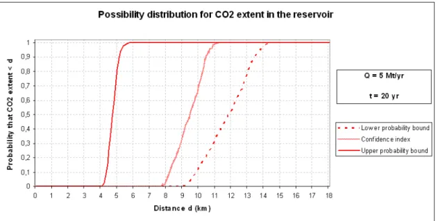
The Independent Random Set method delivers a pair of lower and upper cumulative distribution functions as outcome of uncertainty propagation. This means that we have a lower and an upper bounds for the probability distribution of the considered variable. Figure 2 shows an example of outcome of the CO2 flow model applied to the case of the Dogger aquifer in the Paris Basin.
Obviously assessing risk requires making a decision, which means introducing subjectivity at some point in the process. The hybrid method employed here does not suppress subjectivity. It intends to make it intervene downstream the computation process: the decision maker is provided with a mathematical representation that faithfully reflects the level of knowledge, and, being fully aware of it, can build an informed decision. In the classical probabilistic approach, subjectivity is introduced from the beginning of the computation, hiding imprecision behind a distribution which seems to only represent variability ([23]). Therefore the decision is not made in full awareness of the knowledge of the system.
A shortcoming of the hybrid approach though is that the decision maker is faced with two bounds for the probability distribution, none of them being the actual one. This output might be of uncomfortable use. One bound corresponds to the optimistic vision of the system and would be found non conservative in a risk assessment process. The other one does not account for favourable elements and would be found unduly conservative. A reasonably conservative use would promote the pessimistic bound, without totally excluding values that plead for a more optimistic view. According to [26], we hence propose in the uncertainty computation a weighted averaging of the bounds, with a higher coefficient for the pessimistic one. These weights must be set by the decision maker, depending on the context and his or her behaviour in the face of risk. We suggest values of 2/3 for the pessimistic bound, 1/3 for the optimistic bound as reasonably conservative weighing coefficient in a risk assessment. This weighing delivers a unique probability curve that we dub “confidence index”, as illustrated on Figure 2. This curve can be readily exploited for making decision, while being aware that imprecision is managed through these weighing coefficients. An alternative approach, more in line with the Bayesian philosophy, would be to select such a confidence index for all input parameters tainted with partial ignorance, and run a probabilistic simulation on top of the hybrid one. Either approach yields a subjective plausible prediction, along with higher order uncertainty bounds.
Figure 2: example of possibility distribution for CO2 extent in the reservoir, as resulting from
the application of the CO2 flow model in the Dogger aquifer in the Paris Basin, and confidence
5. PROPOSED WORKFLOW
We recommend that the safety assessment be supported by a Geographical Information System (GIS), figuring the potential conduits between the reservoir and upper layer up to the surface, as well as the vulnerable assets, in particular land use and environmental constraints in surface. The workflow we suggest consists in the three following steps:
1. The reservoir flow model is run to estimate the maximum extent of the CO2 plume, assuming
injection through a single well. We refer to the confidence index for this estimate, while uncertainty propagation permits the analysis of other plausible behaviours if desired. The intent here being comprehensiveness, the 100% confidence index value is employed.
2. Based on this outcome, a risk scenarios identification workshop is held, where the selection of relevant scenarios is justified and documented. In particular, the existing features located in the CO2 extent area and constituting prospective connections between the reservoir and upper layers
can be easily identified with basic GIS tools. Then a probability of being reached may be assigned to each of these conduits from the confidence index curve computed for the reservoir flow model. 3. According to the selected scenarios, the corresponding models are used in a deterministic way.
With regards to cap rock mechanical integrity, the abacus drawn in [14] delivers the tolerable pressure in the injector’s vicinity as a function of site properties to prevent fracturing. For each potential leakage pathway, we determine from the reservoir models the pressure and CO2 front
thickness at the basis. Assuming it will leak, the maximum leakage flow rate is computed for a range of credible properties of the conduit (e.g. well plugs and annular thickness and permeability; fault width, length and permeability). Conversely, it leads to determining the sets of properties that satisfy a maximum flow smaller than the threshold for impacts.
The comparison of the risk models outcomes to the acceptance criteria described above thus determines constraints on natural or operational parameters to guarantee that the critical thresholds are not exceeded. When data are too scarce and the models cannot deliver quantitative requirements, qualitative expectations can be expressed. Overall this process translates into characterisation needs or design constraints for the project. Besides, the performance must be sustained over the long term; additional studies may be necessary to verify it, for instance to take chemical effects into account. The approach being conservative however, it would be inconsistent to consider these results as a necessity. They constitute sufficient conditions, i.e. respecting these constraints ensures that no impact would occur; but it does not exclude that a site is safe with less stringent parameters. Moreover, we underline that our approach stands in the frame of an assessment of risks. Here we assume the occurrence of an abnormal behaviour, e.g. through neglecting capillary entry pressure in our CO2 rise
models; we examine the characteristics ensuring that it nevertheless does not generate adverse consequences on human health or the environment. This process does not represent the expected behaviour, which, in conformity with [27], should achieve long term containment of CO2 in the
storage formation.
6. CASE STUDY
6.1. Site presentation and injection scenario
For the sake of clarity, we exemplify the application of our global workflow on a hypothetical case study in the context of the Paris Basin. This works builds on the results of the PICOREF project ([28]). The region investigated is located in the Southeast of the Paris Basin, about 100 km east of Paris. The storage target is the Dogger limestone aquifer, which depth in this area is about 1500 m. Two zones have been identified in [28] as potential storage sites, the eastern being preferred due to greater thickness of the aquifer. We arbitrarily chose an injection point in this eastern zone outside the environmental protection areas, such that it is roughly equidistant from the three nearest wells (Figure 3). We consider here 20 years CO2 injection at 5 Mt/yr.
Figure 3: Location of the case study, injection point, wells and faults reaching the Dogger top, and some environmental constraints in surface (some of these constraints are not shown here)
6.2. Results
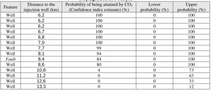
Reservoir flow simulations revealed a maximum extent of 14.8 km. In this radius around the injection well, 13 wells reaching the Dogger top are listed. The three closest wells are located 6.2 km away from the injector. One fault reaching the Dogger top is mapped in this area, 8.4 km south of the injection well. The confidence index for CO2 to attain these features is reported in table 1, which also
indicates the lower and upper probability bounds.
Table 1: Probability for CO2 to reach the potential leakage pathways in our case study (20 years
CO2 injection at 5 Mt/yr)
Feature Distance to the injection well (km)
Probability of being attained by CO2
(Confidence index estimate) (%)
Lower probability (%) Upper probability (%) Well 6,2 100 0 100 Well 6,2 100 0 100 Well 6,2 100 0 100 Well 6,7 100 0 100 Well 6,8 100 0 100 Well 7,0 100 0 100 Well 7,7 99 0 100 Well 8,1 94 0 100 Fault 8,4 84 0 100 Well 8,6 80 0 100 Well 10,8 4 0 73 Well 11,2 0 0 63 Well 12,6 0 0 33 Well 13,3 0 0 12
The well leakage model computes that no adverse impact at ground level is to be feared from the wells located at 6.2 km from the injection as soon as each of them is sealed with:
- a cement plug of thickness and effective permeability such that their ratio is durably greater than 2.1016 m-1 (or a series of plugs such that the sum of these ratios for all of them is greater than this value);
- or a cemented casing covering the whole thickness of the storage aquifer such that the ratio between its thickness and its permeability is durably greater than 3.1018 m-1.
That is to say, a 2 m thick plug with permeability 0.1 mD is enough to verify this criterion; so would be a 3 cm thick casing with permeability 0.01 µD. A similar computation can be performed for each of the other 10 wells recorded in the area. The probability determined in table 1 can be used to weigh the criticality of a leak. We note that the confidence index for reaching the three furthest wells is zero; then these wells should only be considered if the decision maker wants to be particularly cautious and refers to the pessimistic approach. However, this probability does not represent a leakage probability, as it does not incorporate a failure probability (or rather it assumes a 100% failure probability, which would usually not correspond to reality).
The porous column model shows that no adverse impact would occur from leakage through the identified fault if its permeability and its section at surface with a 100 m² plan (corresponding to the surface area of the reference building in our exposure model) are such that their product is smaller than 6.5.10-15 m4. For instance, considering 10 m length for this building, a 10 cm wide fault zone would not generate a hazardous exposure if its effective permeability is smaller than 6.5 mD.
The cap rock mechanical integrity model shows that no tensile fracturing occurs in the injection zone for an injection pressure smaller than 1.7 times the initial pressure. The abacus in [14] demonstrates that shear slip reactivation depends on a number of parameters, among which the initial stress state ratio and the critical internal friction angle are particularly sensitive. Therefore these parameters shall be characterised. When they are respectively greater than 0.7 and equal to 30°, an injection pressure of 1.7 times the initial pressure does not lead to shear slip reactivation either. Under these conditions, this value of overpressure, i.e. 28 MPa, is therefore sustainable.
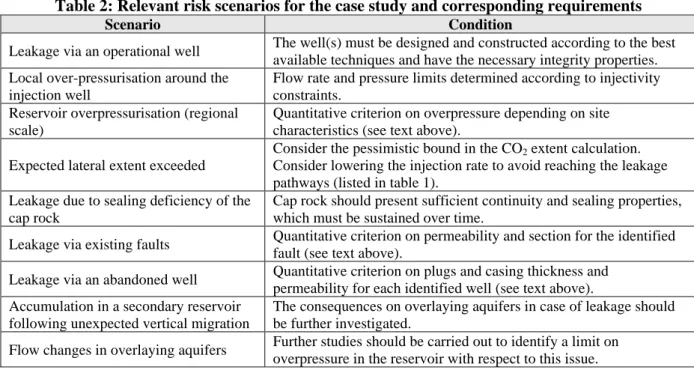
The expert workshop identified globally 9 events to investigate; requirements relating to the other risk scenarios are mainly qualitative at this stage. Further studies would be necessary to translate these conditions into quantitative criteria. The scenarios and corresponding conditions along with additional works needed are reported in table 2.
Table 2: Relevant risk scenarios for the case study and corresponding requirements
Scenario Condition
Leakage via an operational well The well(s) must be designed and constructed according to the best available techniques and have the necessary integrity properties. Local over-pressurisation around the
injection well
Flow rate and pressure limits determined according to injectivity constraints.
Reservoir overpressurisation (regional scale)
Quantitative criterion on overpressure depending on site characteristics (see text above).
Expected lateral extent exceeded
Consider the pessimistic bound in the CO2 extent calculation.
Consider lowering the injection rate to avoid reaching the leakage pathways (listed in table 1).
Leakage due to sealing deficiency of the cap rock
Cap rock should present sufficient continuity and sealing properties, which must be sustained over time.
Leakage via existing faults Quantitative criterion on permeability and section for the identified fault (see text above).
Leakage via an abandoned well Quantitative criterion on plugs and casing thickness and permeability for each identified well (see text above). Accumulation in a secondary reservoir
following unexpected vertical migration
The consequences on overlaying aquifers in case of leakage should be further investigated.
Flow changes in overlaying aquifers Further studies should be carried out to identify a limit on overpressure in the reservoir with respect to this issue.
7. DISCUSSION
The framework we have achieved meets our expectations in terms of simplicity and flexibility. The whole process can be performed in a time-efficient manner; in particular, each of the models requires a computing time of only few seconds per simulation. The simplified models we have adopted constitute an alternative to the catalogue of simulations proposed in the Certification Framework ([29]), which pursues roughly similar objectives to ours. We underline that our approach is not designed to be used without a minimum knowledge of CO2 storage and geology matters: if the various tools are easy to
manipulate, interpreting their results requires a somewhat critical look and a certain caution.
Our approach appears flexible to various degrees of knowledge of the storage complex. The case study presented has been run with data from the literature. Though this area was investigated specifically in the PICOREF project ([28]), no field exploration has been carried out; the dataset can therefore be considered limited. Our application is then representative of an early stage of a storage project. Uncertainties would be reduced and results made more precise when running the proposed approach with an elaborate dataset. Computational efficiency makes it easily possible to run the process several times during a project to progressively incorporate new data acquired throughout the various stages. This approach is also flexible in terms of models used. We developed a consistent set of simplified models that meet the needs for simplicity. However, a user could basically replace every component he desires among them with more sophisticated models, the articulation between them remaining barely changed. For instance, a numerical reservoir model could substitute for our analytical model of CO2 extent and pressure field in the aquifer, the important point being the ability to deliver whether or
not a leakage pathway can be reached by CO2 and what is the pressure at its basis. Swapping models,
however, could affect the capacity to propagate uncertainties. We note nevertheless that in our approach the probability of reaching a conduit is only used as an indicator, and not directly for producing a risk evaluation. Therefore in the case where alternative models are employed with computing time preventing uncertainty propagation through multiple simulations, the user could still globally follow our approach, adopting a different strategy to investigate the effects of uncertainties such as less comprehensive sensitivity studies.
The uncertainty management framework constitutes nonetheless to our view a major strength of the approach described here. Through a rigorous representation and propagation of uncertainty, it leads to an unbiased view of the sources of uncertainty and how further characterisation can decrease it. It serves the purpose of targeting site investigation. Updating the available data in the course of the project as mentioned above, the hybrid method tools would deliver a clear survey of uncertainty reduction in the safety assessment as knowledge of the site increases.
The approached described in this paper incorporates a scenario identification stage, which encompasses all kinds of risks from leaks to geomechanical disruptions. In that respect, it goes beyond the work presented in [29], directly focused on well and fault leakage. However, some risks cannot be quantitatively investigated with the models built so far. A model would be needed for instance for evaluating the hydrodynamic impact in overlaying aquifers as a result of pressure buildup in the storage formation. Brine leakage scenarios have not been modelled either. Besides, further developments could be brought to the CO2 rise models in order to make them less conservative;
attenuation through the geological layers for instance has not been taken into account yet.
Exposure models need to be refined as well. The surface exposure model is particularly pessimistic. CO2 dispersion calculation could be suggested (e.g. [30]) to define a more realistic acceptable leakage
rate; the difficulty would then relate to the level of generality, since Chow et al. [31] demonstrate the need to take account of specific conditions. A similar concern goes for aquifer impacts: site-specific reactive transport modelling of CO2 intrusion into a freshwater aquifer is envisaged, but it
Eventually a benchmark study of the reservoir analytical model versus simple numerical models is underway. It seeks to determine whether it is feasible to extrapolate the results of the analytical model beyond the injection period, in order to improve the treatment of long term risks in our workflow.
8. CONCLUSION
We have described a simple approach for assessing safety of a CO2 geological storage site. It is
flexible and can take into account the specific properties of each site. It involves a set of components designed to be used in a simple and time-efficient manner. It includes an uncertainty management framework that distinguishes between variability and knowledge incompleteness, therefore indicating where uncertainty can be effectively reduced by additional knowledge acquisition. We applied this approach to a case study in the Paris Basin. The application illustrates how qualitative and quantitative inputs are exploited so as to provide conditions that ensure that CO2 storage is safe on the short and the
long term.
Though not a complete risk assessment framework, the demonstrated developments compose a global approach that allows for screening and assessing the critical elements for storage safety at a given site. As currently no risk assessment workflow or safety standards for CO2 storage have been established
and commonly accepted, the approach presented partly fills this gap by giving means to determine safety references. It therefore constitutes one more step toward wide-scale implementation of CO2
capture and storage under safe conditions, which addresses the urge to act to mitigate greenhouse gas emissions while ensuring the absence of significant impacts for populations and the local environment. Acknowledgements
This work has been supported by the French National Research Agency (ANR) through the CO2
programme (project CRISCO2, n° ANR-06-CO2-003). The authors are grateful to their partners Jean-Paul Chilès and Nicolas Desassis (Mines ParisTech), Philippe Renard (CHYN) and Marc Lescanne (TOTAL S.A.) for their input in this project.
References
[1] Intergovernmental Panel on Climate Change. “Special Report on Carbon Dioxide Capture and
Storage”, Cambridge University Press, Cambridge, UK and New York, USA, 442 p. (2005).
[2] International Energy Agency (IEA) “Technology Roadmap – Carbon Capture and Storage”, IEA, Paris, 46 p. (2009).
[3] IEA Greenhouse Gas R&D Programme (IEA GHG). “Role of Risk Assessment in Regulatory
Framework for Geological Storage of CO2: Feedback from Regulators and Implementers”,
Report 2007/2, 88 p. (2007).
[4] IEA Greenhouse Gas R&D Programme (IEA GHG). “Launch meeting of the Risk Assessment
Network”, Report 2006/5, 46 p. (2006).
[5] IEA Greenhouse Gas R&D Programme (IEA GHG). “4th Meeting of the Risk Assessment Network”, Report 2009/7, 24 p. (2009).
[6] J.M. Nordbotten, M.A. Celia and S. Bachu. “Analytical solutions for leakage rates through
abandoned wells”, Water Resources Research, 40, W04204 (2004).
[7] J.M. Nordbotten, M.A. Celia and S. Bachu. “Injection and storage of CO2 in deep saline aquifers: Analytical solution for CO2 plume evolution during injection”, Transport Porous
Media, 55, pp. 339-360 (2005).
[8] J.M. Nordbotten and M.A. Celia. “Similarity solutions for fluid injection into confined aquifers”, Journal Fluid Mechanics, 561, pp. 307-327 (2006).
[9] G. Bellenfant, D. Guyonnet, D. Dubois, O. Bouc. “Uncertainty theories applied to the analysis
of CO2 plume extension during geological storage”, Energy Procedia, 1, 1, pp. 2447-2454,
[10] S.A. Mathias, P.E. Hardisty, M.R. Trudell and R.W. Zimmerman. “Approximate solutions for
pressure buildup during CO2 injection in brine aquifers”, Transport Porous Media, 79, 2,
pp. 265-284 (2009).
[11] A.R. Bowden and A. Rigg. “Assessing risk in CO2 storage projects”, Australian Petroleum
Production and Exploration Association Journal, 44, pp. 677-702 (2004).
[12] O. Bouc, P. Audigane, G. Bellenfant, H. Fabriol, M. Gastine, J. Rohmer and D. Seyedi. “Determining safety criteria for CO2 geological storage”, Energy Procedia, 1, 1, pp. 2439-2446,
Proceedings of GHGT-9 (2009).
[13] F. Wertz, P. Audigane and O. Bouc “CO2 thermodynamic model in a leaking well”, Energy
Procedia, 1, 1, pp. 1791-1798, Proceedings of GHGT-9 (2009).
[14] J. Rohmer and O. Bouc. “A response surface methodology to address uncertainties in cap rock
failure assessment for CO2 geological storage in deep aquifers”, Int. J. Greenhouse Gas
Control, 4, pp. 198-208.
[15] Official Journal of the European Union. “Commission Directive 2006/15/EC of 7 February 2006
establishing a second list of indicative occupational exposure limit values in implementation of Council Directive 98/24/EC and amending Directives 91/322/EEC and 2000/39/EC”, 9.2.2006.
[16] Ministère chargé de l’Ecologie. “Note du 16/11/07 relatif à la concentration à prendre en
compte pour l’O2, le CO2, le N2 et les gaz inertes”.
[17] IEA Greenhouse Gas R&D Programme (IEA GHG). “Study of potential impacts of leaks from
onshore CO2 storage projects on terrestrial ecosystems”, Report 2007/3, 73 p. (2007).
[18] S.M. Benson, R. Hepple, J. Apps, C.F. Tsang, M. Lippmann. “Lessons learned from natural
and industrial analogues for storage of carbon dioxide in deep geological formations”,
Lawrence Berkeley National Laboratory Report LBNL-51170 (2002).
[19] M. Stenhouse, R. Arthur and W. Zhou, “Assessing environmental impacts from geological CO2 storage”, Energy Procedia, 1, 1, pp. 1895-1902, Proceedings of GHGT-9 (2009).
[20] UNSCEAR. “Sources, Effects and Risks of Ionizing Radiation. United Nations Scientific
Committee on the Effects of AtomicRadiatio, 1988 Report to the General Assembly. Annex A.”,
United Nations, New York, USA, 127 p. (1988).
[21] C.V. Shaw. “Mechanical ventilation and air pressure in houses”. Canadian Building Digest CBD-245 (1987).
[22] Official Journal of the European Union. “Council Directive 98/83/EC of 3 November 1998 on
the quality of water intended for human consumption”, 5.12.1998.
[23] S. Ferson, L.R. Ginzburg. “Different methods are needed to propagate ignorance and
variability”, Reliability Engineering and Systems Safety, 54, pp. 133-144 (1996).
[24] L.A. Zadeh. “Fuzzy sets as a basis for a theory of possibility”, Fuzzy Sets and Systems, 1, pp. 3-28 (1978).
[25] C. Baudrit, D. Dubois, D. Guyonnet. “Joint propagation and exploitation of probabilistic and
possibilistic information in risk assessment models”. IEEE Transactions on Fuzzy Systems,
vol.14, N°5, pp.593-608 (2006).
[26] J.Y. Jaffray. “Linear utility theory for belief functions”, Operations Research Letters, 8, 2, pp. 107-112 (1989).
[27] Official Journal of the European Union. “Directive 2009/31/EC of the European Parliament and
of the Council of 23 April 2009 on the geological storage of carbon dioxide”, 5.6.2009.
[28] S. Grataloup, D. Bonijoly, E. Brosse, R. Dreux, D. Garcia, V. Hasanov, M. Lescanne, P. Renoux and A. Thoraval. “A site selection methodology for CO2 underground storage in deep saline aquifers: case of the Paris Basin”, Energy Procedia, 1, 1, pp. 2929-2936, Proc. GHGT-9 (2009).
[29] C.M. Oldenburg, S.L. Bryant and J.P. Nicot. “Certification framework based on effective
trapping for geologic carbon sequestration”, Int. J. Greenhouse Gas Control, 3, 4, pp. 444-457
(2009).
[30] K. Bogen, E.A. Burton, S.J. Friedmann, F. Gouveia. “Source terms for CO2 risk modeling and GIS/simulation based tools for risk characterization”, Eighth International Conference on
Greenhouse Gas Control Technologies (GHGT-8), Trondheim, Norway, 19-22 June 2006. [31] F. Chow, P. Granvold, C. Oldenburg. “Modeling the effects of topography and wind on
atmospheric dispersion of CO2 surface leakage at geologic carbon sequestration sites”, Energy
![Figure 1: Example of probability distribution for salinity in the Dogger aquifer – random sampling on the salinity map in an area investigated for CO 2 storage (left, from [9]); possibility](https://thumb-eu.123doks.com/thumbv2/123doknet/14349399.500637/6.892.122.807.927.1143/example-probability-distribution-salinity-sampling-salinity-investigated-possibility.webp)