READ THESE TERMS AND CONDITIONS CAREFULLY BEFORE USING THIS WEBSITE. https://nrc-publications.canada.ca/eng/copyright
Vous avez des questions? Nous pouvons vous aider. Pour communiquer directement avec un auteur, consultez la première page de la revue dans laquelle son article a été publié afin de trouver ses coordonnées. Si vous n’arrivez pas à les repérer, communiquez avec nous à [email protected].
Questions? Contact the NRC Publications Archive team at
[email protected]. If you wish to email the authors directly, please see the first page of the publication for their contact information.
NRC Publications Archive
Archives des publications du CNRC
This publication could be one of several versions: author’s original, accepted manuscript or the publisher’s version. / La version de cette publication peut être l’une des suivantes : la version prépublication de l’auteur, la version acceptée du manuscrit ou la version de l’éditeur.
Access and use of this website and the material on it are subject to the Terms and Conditions set forth at
Initial gradient in a dense glacial till
Law, K. T.; Lee, C. F.
https://publications-cnrc.canada.ca/fra/droits
L’accès à ce site Web et l’utilisation de son contenu sont assujettis aux conditions présentées dans le site LISEZ CES CONDITIONS ATTENTIVEMENT AVANT D’UTILISER CE SITE WEB.
NRC Publications Record / Notice d'Archives des publications de CNRC:
https://nrc-publications.canada.ca/eng/view/object/?id=0373a11b-64d5-40f1-abad-481193079831
https://publications-cnrc.canada.ca/fra/voir/objet/?id=0373a11b-64d5-40f1-abad-481193079831
Ser
TH1
M21d
National Research
Conseil national
$
Council Canada
de recherches Canada
y- f - --- -BLDG
INITIAL GRADIENT IN A DENSE GLACIAL T I L L
by
K.
T. Law and C.
F. Lee
Reprinted f r o m
Proceedings, 10th International Conference on
Soil Mechanics and Foundation Engineering
Stockholm, 15-19 June 1981
p. 441
-
446
!,
B I B L I O T S ~ Q U E
Rech.
BStirn.
c r . 1 ~ ~ - I I C I S TDBR P a p e r No. 997
Division of Building R e s e a r c h
P r i c e $1.00
OTTAWA
NRCC 19687
SOMMAIRE
Lthydrog6010gie e t l a g6ochimie j o u e n t un
rale
d 6 t e d n a n t dans 1 ' 6 v a l u a t i o n du degr6 d e s 6 c u r i t 6 d e s f a t s contenant d e s d g c h e t s r a d i o a c t i f s e t d e s o p 6 r a t i o n s d e t r a n s p o r t d e ceux-ci; c r e s t pourquoi e l l e s o n t f a i t l ' o b j e t d'une e t u d e c o n d u i t e s u r l e s i t e de l a c e n t r a l e n u c l h i r e de Bruce e n O n t a r i o ,03
d e s d d c h e t s f a i b l e m e n t B moyennement r a d i o a c t i f s s o n t stockEs dans d e s s t r u c t u r e s s o u t e r r a i n e s en beton a d . C e l l e s - c i s o n t i n s t a l l e e s dans un till dense e t s o n t pourvues d'un r g s e a u de d r a i n a g e s o u t e r r a i n . L'Etude p o r t e e n t r e a u t r e s s u r l a d e t e r m i n a t i o n d e s prof i l s du t r i t i u m dans l e s s o l s d g r i v k s du t i l l ; l e s r g s u l t a t s i n d i q u e n t que 1'6coulement s o u t e r r a i n ne s u i t pas l a l o i de Darcy. La p e r m e a b i l i t 6 de c e s s o l s a e n s u i t e Bte d t u d i g e au l a b o r a t o i r e avec un a p p a r e i l s p g c i a l , p e r m e t t a n t de mesurer avec p r 6 c i s i o n un dcoulement i n f i m e e n p r e s e n c e de g r a d i e n t s h y d r a u l i q u e s f a i b l e s . Les r e s u l t a t s exp6rlmentaux montrent q u ' i l e x i s t e un g r a d i e n t i n i t i a l , au- d e s s o u s duquel l e c o e f f i c i e n t de p e r d a b i l i t 6 e s t nu1 ou beaucoup p l u s f a i b l e qu'avec d e s g r a d i e n t s p l u s 6lev6s. Ceci e s t en accord a v e c les p r o f i l s du t r i t i u m mesurds s u r place.Comptes rendus du Dixieme Congres lnternationale de
Mecanique des Sols et des Travaux de Fondations, Stockholm 15- 19 juin 1981
ANALYZED
OFFPRINT
TIRE-A-PART
Editor: Publications Committee of X.ICSMFE
Editeur: Comite des Publications du X. ClMSTF
A.A. BALKEMA/ROlTERDAM/1981
. -
-
---
- < . --->.---.---
-
I.--
-
----.
, ..
. .Proceedings of the Tenth International Conference on
Soil Mechanics and Foundation Engineering, Stockholm 15-19 June 1981
I I
I
Soil Mechanics and Foundation Engineering
Tenth International Conference
IMecanique des Sols et des Travaux de
Fondations
Initial Gradient in a Dense Glacial Till
Gradient Initial du "Till" Glaciaire Dense
K.T. LAW
Division of Building Research, National Research Council of Canada, OttawaC.F. LEE
Geotechnical Engineering Department, Ontario Hydro, Toronto, CanadaSYNOPSIS Hydrogeology and geochemistry, critical factors in evaluating containment trans- port and radiation safety, have been studied at the Bruce Nuclear Power Development site, Ontario, where low to medium level wastes are stored in in-ground reinforced concrete structures. These structures, located in dense glacial till, are provided with a subsurface drainage system. The study included the determination of the tritium profiles in the till soil; the results indicate that groundwater flow appears to deviate from Darcian behaviour. The permeability of the till soil was then studied in the laboratory by means of a special apparatus that permits the accurate measurement of minute flow under low hydraulic gradients. The test results show that there exists an initial gradient below which the permeability coefficient is either zero or sianificantly smaller than that at higher gradients. This is consistent with the tritium profiles measured at the site.
INTRODUCTION
The rapid rise in the cost of fuel oil and the insecurity of its supply have led to the use of nuclear power in a number of countries to meet energy demands. In Canada, nuclear power generation is achieved by means of CANDU reac- tors
-
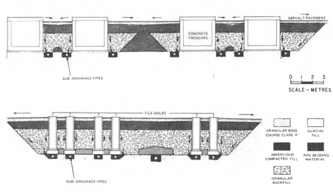
a Canadian design that uses natural uranium as fuel and heavy water as the modera- tor. As in the case of most industrial opera- tions, a number of wastes are produced in the course of reactor operation and maintenance. These wastes are contaminated with low- to medium-level radioactivity. Their volumes are small compared with typical industrial waste volumes, or with the volumes of fly-ash produced at coal-fired stations. A 2000 MWe nuclear power station produces a volume of about 1000 m3(approximately the volume of an Olympic-size swimming pool) per year. The volume is further reduced substantially by incineration, evapora- tion and compaction. Methods of handling and storing these wastes are well developed (Carter and Mentes, 1976), and experience shows that they are both safe and economical. Figure 1 illustrates the two types of in-ground storage facilities used by Ontario Hydro, a provincial electrical utility, for the storage of reactor wastes: concrete trenches, and tile holes. Both of these facilities are provided with a subsurface drainage system. They are located on the site of Ontario Hydro's Bruce Nuclear Power Development, near Kincardine, Ontario, approximately 250 km northwest of Toronto. For such storage facilities, the groundwater systems become the most significant medium through which any radionuclides (or unstable isotopes) acci- dentally released from storage structures canbe transported to the biosphere. Hydrogeology and geochemistry of storage sites become critical factors in evaluating containment transport and radiation safety. Some of these factors have been studied and reported in this paper.
SITE CONDITIONS
The Radioactive Waste Operations site has an area of 7.7 hectares, is relatively flat, and is underlain by 14 to 19 m of Quaternary deposits that rest on interbedded limestone and dolomite of Paleozoic age. Extensive investigations of the site have been carried out over the years, particularly with regard to its physical hydro- geology and geochemistry, and the evaluation of groundwater and contaminant transport. Most of the hydrogeotechnical and geochemical research has been carried out by the University of Waterloo, under contract from Ontario Hydro
(Cherry et al. 1980, Gillham et al. 1980). The overburden at the site consists primarily of a dense glacial till, with some granular (i.e., sand or sand and gravel) layers. The till is oxidized and brown within the upper 1.5 to 3 m of the surface. Below this lies the grey till, which is a dense silt with varying amounts of
fine to coarse sand, clay, fine to coarse gravel and scattered cobbles and boulders. A typical sample of till consists of approximately 50% silt, 25 to 30% sand, 7 to 15% gravel, and 10% clay. It usually has a density of 2300 to 2400 kg/m3, and a moisture content of 5 to 10%. The total porosity of the till is 0.15 to 0.2. The drainable (or effective) porosity of a dense till could be substantially smaller, however, than its total porosity. Debidin and Lee (1980) reported an effective porosity of 0.002 to 0.007 for a dense glacial till near Bowmanville, Ontario, based on drawdown observations. The small value of the effective porosity is attri- buted to the highly compacted till soil.
Conventional permeability tests carried out on the Bruce till indicated a coefficient of perme- ability of the order of 10-10 m/sec. These
\
\
SUB-DRAINAGE PIPES 0
-
1 2 3SCALE - M E T R E S
r I TILE HOLES
GRANULAR BASE GLACIAL COURSE CLASS A T I L L
I
I
m
IMPERVIOUS PIPE BEDDING COMPACTED T I L L MATERIAL
\
SUB-DRAINAGE PIPES
GRANULAR BACKFILL
Fig. 1 Concrete trenches and tile holes for in-ground storage of reactor wastes
tests consisted of laboratory permeameter tests using relatively large hydraulic gradients and pour/bail tests using piezometer nests installed at the site. The fractured bedrock has a permeability of 10-7 to 10-5 m/s, which is several orders of magnitude higher than that of the till. As a result, an underdrainage situa- tion develops in the till, and the rate of vertical groundwater flow becomes an important factor in safety assessment. In general, two approaches could be used to evaluate the rate of groundwater flow: (i) by computation based on Darcy's law, and (ii) by determining the age of the groundwater as a function of depth.
It was in connection with the latter approach that tritium profiles in the till were deter- mined. Tritium is an isotope of hydrogen, deposited in surficial soils around the world during the 1950's following the atmospheric testing of hydrogen bombs. By measuring the depth of penetration of tritiated water, it was possible to determine the rate of flow in some areas where underdrainage occurred. Figure 2
gives a typical tritium profile thus determined in the till soil at the Bruce site. The profiles obtained actually resembled diffusion profiles, i.e., they could be explained largely
in
terms of molecular diffusion, in the absence of any Darcianor
physical flow of the groundwater itself. Bad there been a significant flow, the concentration of tritium would probably decrease more abruptly at a greater depth as determined by the effective porosity and the permeability coefficient.The possibility of non-Darcian behaviour in the dense till was thus explored, using a special
T R I T I U M U N I T S
400 1 0 0 0
G R O U N D W A T E R T A B L E
Fig. 2 Typical tritium profile measured in till
laboratory apparatus which permitted accurate measurement of minute flow under low hydraulic gradients.
DESCRIPTION OF APPARATUS
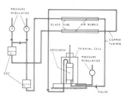
The complete apparatus is shown schematically in Figure 3 and graphically in Figure 4. Basically, it consists of an ordinary triaxial cell connec- ted to a system for applying hydraulic gradients
T R l A X l A L C E L L
V A L V E
and for measuring the result- ing flow rates through the specimen.
The use of the triaxial cell permits the application of any principal stress System to the specimen. A back pres- sure (150 kPa) is used to maintain specimen saturation during consolidation and the subsequent permeability test. Three membranes are used to prevent leakage. The first is of the thin Ramses type to provide good contact with the somewhat uneven side surface of the specimen and the other two are ordinary rubber mem- branes. Thin coats of pipe thread sealer are applied between the membranes.
The hydraulic gradient, i, is applied using pots connected to the specimen ends. The one at the bottom end is station- ary; the other can be cranked up and down. The difference
Fig. 3 Schematic diagram of the permeability apparatus between water levels in the
pots, after subtracting the hydraulic resistance in the system, is equal to the total head difference across the specimen length
(50 mm)
.
The hydraulic resistance in the systemfor the present test series was determined to be
3.7 mm head of water. The applicable range of
head difference is from 0 to 1.0 m, correspond- ing to i of 0 to 20. The accuracy of measure- ment of the head difference is about +1.0 mm, and thus the precision for i is +0.02. For
i < 20, both pots are pressurized by the same
back pressure; for i > 20, a higher back pres-
sure is applied to the pot connected to the top end of the specimen. The test is conducted essentially under a constant head because the small quantity of water transported between the relatively large pots (102 mm in diameter) does not significantly alter the water levels during the test.
Two horizontal. calibrated. alass tubes are . a
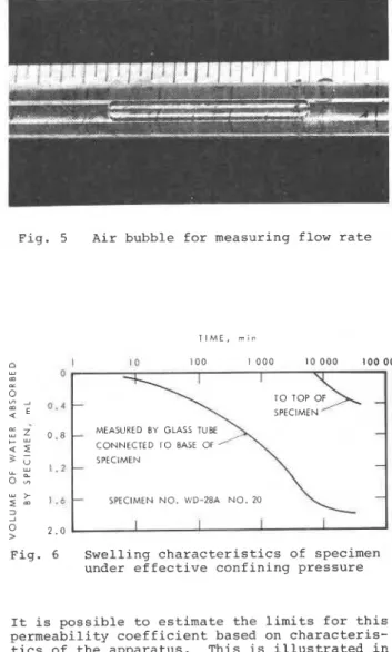
installed between the pots and the specimen. The tubes are carefully cleaned using a chromic- sulphuric acid solution followed by a laboratory glassware detergent and then thoroughly rinsed with distilled water. An elongated air bubble is
trapped in each tube (Figure 5). The advancing
and receding menisci in the tube are round, indicating that the tube is clean; the almost unnoticeable difference between the contact angles of the menisci means that the hydraulic resistance of the bubble is small. The flow rate in each tube can be determined by reading the movement of the bubbles regularly. Any discrep- ancy between the two flow rates (into and out of the specimen), is due to system leakage or to
the process of creep or swelling of the specimen.
The volume of flow can be measured to an accuracy of +0.0003 mL.
Fig. 4 Permeability test on a dense till
specimen (1
-
triaxial cell; The system was carefully checked for leakage.2
-
specimen; 3 6 4-
glass tube; As a result, some questionable valves andtube-samples by a rubber-carborundum blade mounted on a glass cutting machine.
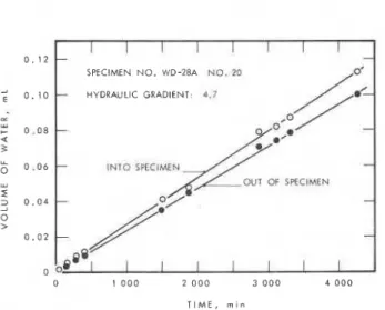
All specimens showed some swelling although effective confining pressures of 103 to 150 kPa were applied. A typical swelling curve is shown in Figure 6. A waiting period of up to a month was allowed for the rate of swelling to reach a
small value before permeability was measured which was done by applying various hydraulic gradients to the specimen. In some cases, however, the effect of swelling was still obser- vable, with the result that volume flow into the specimen was slightly larger than the volume flow out (Figure 7)
.
For these cases, the actual flow was taken as the average of the two flows.Fig. 5 Air bubble for measuring flow rate
The flow rates at different gradients for all the specimens are shown in Figure 8. The relation- ship can be approximated by a straight line intercepting the horizontal axis at an initial gradient io:
where v = velocity of flow
k = coefficient of permeability Each io value was obtained by extrapolation and confirmed by the lack of flow at i smaller than io. This value was found to range from 0.10 to 2.9 and the coefficient of permeability from 4.2 x 10⁻¹¹ to 1.3 x m/s.
DISCUSSION
Equation (1) differs from Darcy's law which states that the flow velocity is directlypropor- tional to the applied hydraulic gradient. The present non-Darcian behaviour is marked by the existence of an initial gradient. This initial gradient, however, does not necessarily imply that there is absolutely no flow at smaller hydraulic gradients. Flow may occur under such circumstances, but the rate is probably too low to be detected in the laboratory. In other words, the permeability coefficient at gradients smaller than the critical, if any, will be substantially smaller than the corresponding value at high gradients.
Sample NO. WD-25 #20 WD-28A #20 WD-32 WD-33 S-26 WD-33 S-24 WD- 2 6 Depth, m TIME, m i n I C 100 1 0 0 0 lo 0 0 0 100 000
MEASURED BY GLASS TUBE
CONNECTED TO BASE OF
'-
SPECIMEN-
-
SPECIMEN NO. WD-2BA N O . 20Fig. 6 Swelling characteristics of specimen under effective confining pressure
It is possible to estimate the limits for this permeability coefficient based on characteris- tics of the apparatus. This is illustrated in Figure 9 with the following symbols:
v1 = lowest reliable flow velocity detectable by the apparatus (2.3 x 10⁻¹¹ m/s)
,
il = hydraulic gradient corresponding to vl,
kl = upper limit of permeability coefficient.
TABLE I
Summary of Test Results Natural moisture Consolidation content, pressure, % kPa Initial Permeability gradient, coefficient, i o m/s
I
I
I I I I I I-
-
SPECIMEN NO. WD-28A NO. 20
-
HYDRAULIC GRADIENT: d.7-
-
INTO SPECIMEN - --
II
I 2 . 0 0 . 1 2;
0. lo<
1 . 6 E w:
0.08 m u 0 - 3 x 1 . 2 0.06 > u, r-
I U 3 0.04:
0.8 0 u > > 0.02 32
u 0 . 4 0 0 1 0 0 0 2 0 0 0 3 0 0 0 4 0 0 0 T I M E , m l n 0Fig. 7 Volumes of water flowing into and out 0 4 8 1 2 16 20
of specimen during permeability test
H Y D R A U L I C G R A D I E N T
Fig. 8 Results of permeability tests
The upper limit of permeability coefficient refers to the situation where the apparatus fails totally to register any flow equal to or less than vl. The lower limit is zero and a probable flow behaviour is represented by the dashed line in Figure 9. The equation for kl is
l i l l i
(2
G
=
~
=
1F
+
~
> +-
U
The values of kl for the six tests are shown in
2
Table 2. They are about 2 to 50 times smaller z
than the corresponding values of k. 3
2
The in situ downward hydraulic gradient at the LL
site is low. Based on piezometric readings, the gradient is estimated to be in the range of 0.5 to 1.0, which lies within the range of the measured values of initial gradient. It is
therefore possible that the apparent lack of flow H Y D R A U L I C G R A D I E N T , I
as indicated by the tritium profile is caused by
the existence of an initial gradient for flow. Fig. 9 Illustration showing method of obtaining
possible upper limit of permeability
The concept of initial gradient
-
while both coefficient at low gradientsinteresting and significant
-
has not been vi = lowest reliable flow velocityincorporated into the over-all assessment of detectable by the apparatus
contaminant transport and radiation safety at
the Bruce site. An element of redundancy gener- il = hydraulic gradient corresponding to
ally prevails in the management of radioactive v1
wastes, calling for the provision of multiple
io = initial gradient
barriers and conservatism in design. The authors believe that this exclusion of the concept from
kl = upper limit of permeability the safety analysis permits a more objective,
technical investigation of an otherwise coefficient at v < vl
potentially controversial subject.
TABLE I1
CONCLUSION Maximum Possible Permeability Coefficient k l r
Below Initial Gradient Using the special apparatus described in this
paper, a non-Darcian flow behaviour was found Sample klg
for a dense till from the Bruce Nuclear Power No. m/s
Development site, Ontario. Above an initial
gradient the flow velocity is linear with the WD-25 #20 8.7 x 10-l1
hydraulic gradient, and the permeability coeffi- WD-28A #20 2.8 x 10-l1
cient is of the same order of magnitude as that WD-32 7.5 x 10-l2
obtained by other conventional tests. Below the WD-33 S-26 3.5 x 10-l1
initial value the flow behaviour is c:~aracterized WD-33 S-24 2.1 x 10⁻¹⁰
by a permeability coefficient either equal to WD-26 6.1 x 10-l1
445
A'
zero or significantly smaller than that at Cherry, J.A., Gillham, R.W. and Harris, R. higher gradients. This behaviour is apparently (1980). Hydrogeologic Investigations of consistent with the tritium profiles measured in the Bruce NPD Radioactive Waste Operations the till at the Bruce site. Site 2, Part 1, Physical Hydrogeological
Studies, Report of Investigations 1977-79. Ontario Hydro Report No. 80069.
ACKNOWLEDGEMENTS
The authors gratefully acknowledge the effort of conducting the field and laboratory tests by the technical staffs of the Division of Building
Research, National Research Council of Canada, Debidin, F. and Lee, C.F. (1980). Groundwater and of Ontario Hydro. This paper is published and Drawdown in a Large Earth Excavation. with the approval of the Director of the Canadian Geotechnical Journal, Vol. 17, Division of Building Research and the Director NO. 2, May 1980, pp. 185-202.
of Design and Development, Ontario Hydro.
REFERENCES
Gillham, R.W., Johnston, H.M. and Cherry, J.A. Carter, T.J. and Mentes, G.A. (1976). Ontario (1980). Hydrogeologic Investigations of
Hydro Waste Storage Concepts and the Bruce NPD Radioactive Waste Operations Facilities. Proc. Symp. on Waste Site 2, Part 11, Distribution Coefficient Management, Tucson, Arizona, October, 1976, Studies, Report of Investigations 1978-79.
Soil mechanics and foundation engineering
-Proceed-
ings of the 10th international conference, Stockholm,
15-1 9 June 1981
1981,28 cm, c.3500pp., 4 vols., Hfl.850
1
$380 / £ l 7 0
Over 500 papers (40 in French, rest English) from con-
tributors throughout the world. Prediction and perfor-
mance; tunnelling in soils; groundwater and seepage
problems; laboratory testing; soil/structure interaction;
environmental control (incl. waste material); soil
exploration and sampling; pile foundations; saving cities
and old buildings; soil dynamics; slope stability; soil
improvement.
All
papers were selected and reviewed by
the national societies of the International Society for
Soil Mechanics and Foundation Engineering.
CONTENTS
1. Prediction and performance (Accuracy of predictions and its determination; Application of probability and decision theory design; Factors governing the performance of buildings and other structures). Pile foundation problems in white chalk; Settlements under intermittent loading; Settlement calculation by a new strength theory; Construction of a pile wall in a rock- fill dam; Rheological definition of loess subsidence; Insulation for foundations and buried services; Land reclamation using fine-grained dredged material; Settlement analysis of tanks on soft clay; Pitfalls of back-analyses; Observations of creep during heave; Consolidation of sensitive clays; etc.
2 Tunnelling in soils (Case records of tunnel constructions;
Effects of different excavation/construction techniques; New calculation methods; Mapping and control systeins). Strain field around a tunnel in stiff soil; Principles of tunnel design for seismic regions; Analytical study of NATM; etc.
3. Groundwater and seepage problems (Prediction and measure-
ment of groundwater conditions and flow; Internal erosion and piping, hydraulic fracturing, etc.; Control of ground water; Effects of changes in groundwater level). Theory of non-linear seepage; Experience in plastic filter application; Jet grout method and cut-off walls stability; Soil drainage and stability of slopes; Initial gradient in a dense glacial till; Structural improvement of alluvial soils; Seepage interaction ctc.
4. Laboratory testing (Relevance of laboratory soil testing
methods; Standardization of laboratory tests for practical application; New laboratory testing methods; Model tests). Investigation of soils creep; Mechanical properties of soft rock and rock mass; Laboratory and pressuremeter tests on a stiff clay; Laboratory testing of vertical drains; The consolidat~on properties of a soft rock; Dynamic compaction of rockfill samples; Model for determining of soil parameters; ctc.
5. Soil structure interaction (Case histories and observation of
real behaviour; Design and construction procedures which take account of soil/structure interaction; Acceptable deformation in relation t o the performance and function of structures). An elastoplastic analysis of anchored walls; Computing foundation slabs with building rigidity; Soil interaction in buried structures; A method of settlement calculation; On the validity of Wink- ler's principle; Design and monitoring of an embankment on alluvium; Anchor slab structure retains earth fill; etc.
6. Environmental control (Waste material in earth structures
and protection against groundwater pollution; Erosion protec- tion; Change of geotechnical properties due to pollution; Sub- sidence due to lowering of the groundwater level and t o the withdrawal of oil and mining). Fly ash as fill material; Mecha- nical behaviour of coal fly ashes; Mechanisms for detoxifying soil; Pollution in peats; Environment protection in Italy; etc. 7. Sod exploration and sampling (In-situ testing and deforma- tion measurements; Quality (scatter) of soil data in relation to specific foundation problems; New techniques for soil sampling and penetration tests). Portable geotechnical field equipment; The static-dynamic penetrometer; Geological interpretation of SIR data; Energy dissipation on the SPT rods; Field investiga- tions of clay soils; A sampler with a new type of shutter; Tests in alluvial sand with the PQS probe; etc.
8. Pile foundations (Use of stress-wave theory in prediction of
pile performance; Control methods for driven and cast-in-place piles; New pile systems and new pile driving methods; Friction piles; Behaviour of pile groups; Failure of pile foundations). Pile foundation settlements; Load test on friction piles in clay; Bearing capacity of pile preloaded by downdrag; Consolidation due t o lateral loading of a pile; Downdrag on bitumen coated
piles in a warm climate; Skin friction on underslurry piles; H
steel piles in dense sand; Load tests on large bored piles in sand; Installation of piles for marine structures in the Red Sea;
9. Saving cities and old buildings (Geotechnical problems con-
nected with the protection of existing structures against sub- sidence and floods; Investigation of the integrity, durability and bearing capacity of structures; Underpinning and other methods of saving structures and ground). Foundation docu- mentation for conservation planning; Preservation of old build- ings in the USSR; The Tower of Pisa: recent observations; etc.
10. Soil dynamics (Design of machine foundations; Damage
by vibrations and protection of buildings and structures; Effect of dynamic loads on strength and deformation properties of soils). Prediction of seismic pore-water pressures; Characteris- tics of embankment dams during earthquakes and man-in- duced vibrations; Displacements of cyclically loaded structures embedded in sands; Saturated sands under cyclic loading; etc.
11. Slope stability (Detection and classification of potential
landslide areas; Factors influencing the short- and long-term stability of slopes; Analysis of slope stability, including dams; Slide warning systems and methods of prevention of land- slides). Stability of natural slopes in quick clay; Dynamic pro- gramming in dam slope design; Relationship between limit equilibrium slope stability methods; etc.
12. Soil improvement (Compaction; Reinforcement of soil;
Grouting, excluding control of groundwater flow and seepage; Consolidation by preloading and/or vertical drains, electro- osmosis, etc.; Soil stabilization by ion exchange; Thermal stabi- lization). Geodrain installation at Lornex Tailings Dam, Cana- da; Soil nailing: a technique of in-situ reinforced earth; Soil improvement by lime-fly ash slurry injection; etc.
Discussions and additional papers (In vol. 4, end 1981).
Soft ground tunneling
-Failures and displacements
1980,25 cm, c.200 pp., Hfl.45
/
$22.00
/
£9.00
Based on a specialty session on soft ground tunneling
held during the 6th Panamerican conference on soil
mechanics and foundation engineering, held in Lima,
Peru in December 1979. Geotechnical problems;
weathered-rock portion of the Wilson tunnel, Honolulu;
failure of shafts
&
tunnels in soft soils; lost ground sub-
sidences in 2 shallow tunnels; assessment of tunnel sta-
bility in clay by model tests; settlements upon soft-
ground tunnelling; tunnels under compressed air; pre-
diction of surface movements; stress path approach for
a tunnel driven in stiff clay; etc. Editors: Director
&
scientist at Inst. Ingenieria, Univ. Mexico.
Weak rock
-Proceedings of the international sym-
posium, Tokyo, 21 -24 September 1981
1981, 25 cm c.1500 pp., Hfl.396/$195.00 /£79.50
Knowledge on weak rock has become increasingly
important for the design and construction of dams,
underground openings, undersea tunnels, mines, foun-
dations of nuclear power stations, large suspension
bridges and transmission towers, long slopes, etc.
The papers and discussions are by engineers interested
in engineering properties, in situ investigations, special-
ized theories, analyses, adequate designs, construction
practices, dynamics and tectonics. The symposium
was sponsored by
I S R M , I S S M F E ,
etc.
This publication is being distributed by the Division of Building R e s e a r c h of the National R e s e a r c h Council of Canada. I t should not b e reproduced i n whole o r in p a r t without p e r m i e s i o n of the original publisher. The Di- vision would be glad to be of a s s i s t a n c e in obtaining such permission.
Publications of the Division m a y be obtained by m a i l - ing the a p p r o p r i a t e r e m i t t a n c e ( a Bank, Exprese, o r P o s t Office Money O r d e r , o r a cheque, m a d e payable to the R e c e i v e r G e n e r a l of Canada, c r e d i t NRC) t o the Natianal R e s e a r c h Council of Canada, Ottawa. K I A OR6. Stamps a r e not acceptable.
A l i s t of a l l publications of the Division i s available and m a y b e obtained f r o m the Publications Section, Division of Building R e s e a r c h , National R e s e a r c h Council of Canada, Ottawa. KIA OR6.