HAL Id: hal-03002410
https://hal.archives-ouvertes.fr/hal-03002410
Submitted on 12 Nov 2020
HAL is a multi-disciplinary open access
archive for the deposit and dissemination of
sci-entific research documents, whether they are
pub-lished or not. The documents may come from
teaching and research institutions in France or
abroad, or from public or private research centers.
L’archive ouverte pluridisciplinaire HAL, est
destinée au dépôt et à la diffusion de documents
scientifiques de niveau recherche, publiés ou non,
émanant des établissements d’enseignement et de
recherche français ou étrangers, des laboratoires
publics ou privés.
Space Charge Behaviours in Cable Insulation under a
DC-Superimposed Pulsed Electric Field
Dongxin He, Zhang Tao, Meng Fansong, Qingquan Li, Wei Wang , Hongshun
Liu, G. Teyssedre
To cite this version:
Dongxin He, Zhang Tao, Meng Fansong, Qingquan Li, Wei Wang , et al.. Space Charge Behaviours
in Cable Insulation under a DC-Superimposed Pulsed Electric Field. High Voltage, IET, 2020.
�hal-03002410�
1
Space Charge Behaviours in Cable Insulation under a DC-Superimposed
Pulsed Electric Field
Dongxin He
1, Tao Zhang
1, Fansong Meng
1, Qingquan Li
1*, Hongshun Liu
1, Gilbert Teyssedre
21
Shandong Provincial Key laboratory of UHV Transmission Technology and Equipment School of Electrical Engineering, Shandong University, Jinan 250061, China
2 University of Toulouse; UPS, INPT, CNRS; LAPLACE (Laboratoire Plasma et Conversion d’Energie); 118
Route de Narbonne, F-31062 Toulouse Cedex 9, France *[email protected]
Abstract: When HVDC cables are subjected to a DC-superimposed pulsed electric stress, the pulsed voltage applied facilitates electrical tree generation and breakdown; however, the mechanism involved remains unclear. To study the deterioration mechanism of cable insulation under a pulsed electric field, an experiment on the dynamic characteristics of space charge under a DC-superimposed pulsed electric field was conducted. For this experiment, a pulse time trigger control circuit was developed to accurately measure the change law of the space charge in cross-linked polyethylene samples at the rising and falling edges of the pulsed electric field. The experimental results showed an unusual change law: the space charge density increases with falling voltage amplitude and decreases with rising voltage amplitude. The sudden change in the electric field breaks the balance of the forces acting on the space charge, leading to injection, extraction, and migration. The energy released during these dynamic processes may destroy the microstructure of the insulation material and contributes to the growth of the electrical tree. This study provides an insight on the initiation mechanism of electrical tree in HVDC cables and proposes a strategy to suppress electrical tree initiation.
1. Introduction
Cross-linked polyethylene (XLPE) cables are widely used in HVDC transmission systems owing to their excellent electrical and mechanical properties. The operational reliability of XLPE cables is vital for the safety and stability of HVDC power systems [1]. Any deterioration of the XLPE cables can compromise the safe operation of the entire transmission system. Therefore, it is important to analyse the cause of cable insulation failure and propose solutions to improve the reliability and safety of cable operation. This can help improve power safety and reduce maintenance costs. Space charge is a vital factor leading to the dielectric aging and breakdown of DC cables [2, 3]. Electrical tree development is considered the main cause of cable aging, leading to breakdown. The initiation and growth of the electrical tree may be driven by the behaviour of space charges [4, 5]. The space charges accumulated inside an insulation material modify the electric field distribution, and the injection, extraction, trapping, and detrapping processes of the space charges are accompanied by energy transfer and release, which may destroy the microstructure of the cable material [6].
An HVDC cable in operation is affected by lightning overvoltage, switching surges, and commutation failure, leading to various shapes of pulsed electric fields superimposed on the nominal DC voltage [7]. Recent studies suggest that the pulsed electric field has an important effect on the electrical tree initiation and breakdown of DC cables. When a DC voltage is applied to the cable insulation, the electrical tree cannot easily initiate and grow, despite the considerable accumulation of the space charge [8]. However, under a DC-superimposed pulsed electric field, the onset voltage for electrical tree initiation is lower than that under a DC electric field alone, thus facilitating electrical tree propagation [9,10]. Moreover, the electrical tree grows with the variation in the voltage amplitude but does not grow at constant voltage [11]. This experimental phenomenon was attributed to the dynamic behaviour of the space charges, i.e., the space charges are trapped and detrapped under the impact of pulsed voltage while the energy released during these processes degrades the microstructure of the insulator [12], leading to breakdown.
The generation of the electrical tree is pronounced when a cable insulation is grounded after DC polarization [13]. This is attributed to the effect of the fast-varying voltage applied to the space charges when grounding [14]. Thus, it can be
2 concluded that the dynamic behaviour of the space charges
under pulsed voltage plays an important role in the initiation of the electrical tree and degradation of the cable insulation. To investigate the deterioration mechanism, it is important to study the space charge behaviour under a DC-superimposed pulsed electric field [15].
Few studies have been conducted on the charge characteristics under pulsed voltage. The dynamic behaviours of surface charges exhibit a close relationship with flashover [16,17]; however, the surface charges cannot be measured using the surface potential method at the same time as under pulsed voltage application. The pulsed electroacoustic (PEA) method can be used to synchronously measure the space charge in the process of stress application; the space charge from the slope with a rise time in the millisecond time range has been studied [18-20]. Some researchers investigated the space charge accumulation characteristics under a square-wave voltage with different parameters (polarity, frequency, duty ratio) [21]. According to the analysis of research on electrical tree, the space charge behaviour at the edge of the pulse voltage may adversely affect cable insulation. However, recent studies have not focused on the dynamic characteristics of space charge at the rising and falling edges.
Measuring the space charge dynamic characteristics under a DC-superimposed pulsed electric field requires a precise pulsed-voltage-controlling technology. In this paper, the PEA method was improved and the space charge was successfully measured online by matching the charge measurement time with the pulse edge. Through the improved platform, the space charge behaviour under a DC superimposed pulsed electric field, especially at the rising and falling edges of the voltage, was observed and analysed. This study provides valuable insight on the initiation mechanism of electrical tree in HVDC cables and proposes a strategy to suppress electrical tree initiation.
2. Experiment
2.1. Experimental Platform
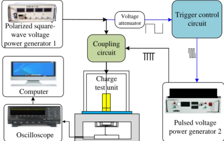
Based on the measurement principle of the PEA method, an experimental platform for testing the space charge was built. Fig. 1 shows a schematic of the space charge test system. It is composed of charge test unit, two pulsed power generators (one is square-wave voltage - power generator 1 for material stressing, the other is pulsed voltage power generator 2 for space charge probing by PEA), trigger control circuit, coupling circuit, oscilloscope and computer. The black arrow lines show the flow of high pulsed voltage, while the blue arrow lines show the flow of low voltage signal.
The key objective of this experiment was to accurately match the space charge test pulse voltage with the rising and falling edges of all the test cycles. The pulse voltage trigger time control method was used to design a “trigger control circuit”, which outputted a trigger pulse to measure the space charge at a specified time, thereby realizing a flexible control of the space charge test time under a periodic electric field. The trigger control circuit transforms the polarized square-wave signal from power generator 1 into tens of short continuous square-wave signals, which are
synchronous with different phases of the polarized voltage, such as the rising and falling edge, and the specific time in the high-voltage and low-voltage level. The power generator 2 that is used to probe space charge is triggered by the short square-wave signal from trigger control circuit to output continuous pulsed voltage with 5ns rising edge. The polarized square-wave voltage from power generator 1 and the synchronous pulsed voltage from power generator 2 are applied on the test sample simultaneously through coupling circuit, thus space charge distribution and dynamics can be measured under polarized square-wave voltage. The charge measurement signal is acquired by oscilloscope and transmitted to the computer, and the raw signal can be calibrated and recovered to obtain charge profiles by waveform processing program.
Trigger control circuit Coupling circuit Pulsed voltage power generator 2 Polarized square-wave voltage power generator 1 Computer Oscilloscope Voltage attenuator Charge test unit
Fig. 1. Schematic of space charge measurement system.
Fig. 2 shows a schematic of the trigger control circuit, which is composed of isolation transformer, filter, zero-crossing comparator, phase adjuster, signal converter and optocoupler. Its working principle is as follows: the high pulsed voltage produced by the Polarized square-wave voltage power generator 1 is converted to a low-voltage pulse signal by an attenuator. The square-wave signal is synchronized with the pulse voltage by subjecting the signal to filtering, zero-crossing comparator circuit, and time-delay processing. The converter then generates a fixed number of short square-wave signals (the number is 59 in this research) to trigger the Pulse voltage power generator 2. A train of voltage pulses is then transmitted to the PEA cell for charge detection. Through calibration, the matching accuracy of the trigger control circuit can be at the nanosecond level.
Fig. 2. Schematic of the trigger control circuit.
Isolation transformer filter Zero-crossing comparator Phase correction Optocoupler Signal converter
2.2. Experimental Preparation
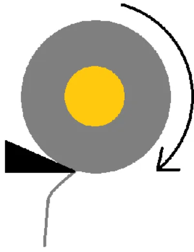
To study the characteristics of the space charge in XLPE cables, the XLPE samples were made into sheets. The samples used in these experiments were cut from a 10 kV XLPE-insulated cable with a size of 5×5 cm² and a thickness of 240 µm. The cutting method is schematized in Fig. 3. A section of the cable was installed in a rotary machine and cut by a lathe whose knife was moving forward in a tangential direction. The width and flatness of the peelings were optimized by adjusting the rotation speed of the cable section and the moving speed of the lathe knife.
Fig. 3. Cutting method scheme of cable insulation.
As electrical tree initiation is sensitive to the polarity of the DC field, we employed the easiest method to initiate the electrical trees, i.e., by applying a negative voltage [22]. The power supply led to the superposition of the DC voltage level and the square-wave voltage with a low level of −3.6 kV and a high level of −7.2 kV as the polarization voltages, at a frequency of 50 Hz. In this experiment, the falling edge represents the change from the high level of −7.2 kV to the low level of −3.6 kV, and the rising edge represents the change from −3.6 to −7.2 kV. Both the rising and falling edges of the square wave were set to 50 µs. Fig. 4 shows the
voltage waveform. The electric field strengths
corresponding to the low and high levels are −15 and −30 kV/mm, respectively, and the polarization time is 2 h.
Fig. 4. Waveform of DC-superimposed square signal. (In red color: trigger for pulsed voltage generation).
The pulsed voltage used to measure the space charge is accurately matched with the polarized square-wave voltage, to compare the change in the space charge before and after the edges. A fixed number of pulse sequences are generated by the pulse trigger circuit in each test period. The interval for probe pulse generation is 334 µs; this corresponds to 59 test points in one period of 20 ms. As shown in Fig. 4, the test points 1 to 30 are at low-voltage levels of the stress waveform, while the rest 31-59 are at high-voltage levels. To obtain an appropriate signal-to-noise ratio, the acoustic signals are averaged over 166 periods of the square voltage, yielding a total measurement time of 3.32 s. Fig. 5 shows the matching result of the probe pulsed voltage and square stress voltage. The time corresponding to the rising and falling edges is 50 µs, and the matching accuracy is at the nanosecond level, which is sufficient for the accuracy of the measurement. The most important objective was to measure the space charge immediately after the rising and falling edges, such that the dynamic features of the space charge at the rising and falling edges can be observed. By comparing the variation of the space charge distribution before and after the edges, we can analyse the mechanism of space charge motion and then summarize its behavioural characteristics at the rising and falling edges. Moreover, the accumulation and attenuation characteristics of the space charge can be obtained from the measurements taken at high and low voltage levels at different times.
Fig. 5. Matching relationship between space charge test time and polarization pulsed voltage.
3. Experiment Results
3.1. Space Charge Accumulation
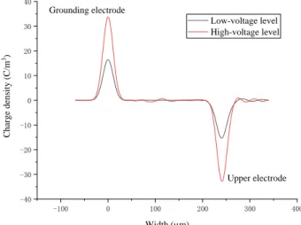
The space charge measured using the PEA method, like with any other perturbation method, is the net charge present locally, and may lead to the superposition of the electronic and ionic carriers with different charge polarities. Fig. 6 shows the waveform of space charge at the initial time on an XLPE sample that was never subjected to an electric field before. In order to improve the signal to noise ratio, signals
-3.6 -7.2 Voltag e (kV ) Time (s) 1 30 31 59 High-voltage level Low-voltage level Falling edge Rising edge
4 in 166 continuous periods of square-wave voltage are
acquired, and the original signals are averaged in 166 times to get smooth waveform. After that the raw signal is calibrated and recovered to obtain charge profiles by waveform processing program, in which the overshoot and the attenuation of the signal caused by the system are recovered and Gaussian filter is used to make the waveform clean. As shown in Fig. 6, only capacitive charges are detected at the interface with the electrode, with no space charge inside the XLPE. Moreover, the space charge peak amplitude is proportional to the voltage (x2 between low and high voltage levels).
-100 0 100 200 300 400 -40 -30 -20 -10 0 10 20 30 40 Upper electrode Charge de nsity (C/m 3) Width (µm) Low-voltage level High-voltage level Grounding electrode
Fig. 6. Waveform of space charge at initial time.
Fig. 7 illustrates the process of space charge evolution under a low-voltage level with the electric field of −15 kV/mm and a high-voltage level with the electric field of −30 kV/mm in the XLPE samples in a stressing time of 2 h. The experimental results show that as the time of applied polarization voltage increases, the space charges with a polarity opposite to those on the interface charges at the electrode are gradually accumulated at the two ends of the XLPE sample. It needs to be mentioned that the electric field of -15 kV/mm does not reach the threshold electric field to generate space charges, as scarce charges accumulated inside the sample when the sample was subjected to DC -15 kV/mm stress. Thus the space charges detected in the lower stress level of the square-wave voltage come from the charges generated in the higher level of -30 kV/mm and also during the rising and falling edges, and the generated charges experience few dissipation in the low level.
Because the applied electric field is not very high, the space charge injected from the electrode is less than that generated by the internal impurity ionization. As a result, the heteropolar space charge is mainly composed of positive and negative ions that come from impurity ionization. In the process of XLPE cross-linking, dicumyl peroxide, a type of cross-linking agent, decomposes and produces various cross-linking by-products such as methane, cumyl alcohol, acetophenone, and methyl styrene [23,24]. Cross-linking by-products are reported to dissociate under an electric field, and the greater the electric field strength, the greater the charge dissociation. Furthermore, the positive ions migrate to the cathode, and the negative ions migrate to the anode. Traps are generated because of the chemical and structural
defects in the XLPE insulation material, mostly in the amorphous zone. These traps will trap the ions dissociated by the cross-linking by-products. As the energy level of the traps increases, it becomes more difficult for the trapped space charge to escape. With time, a large number of heteropolar space charges accumulate near the interfaces of the XLPE. -100 0 100 200 300 400 -30 -20 -10 0 10 20 30 Upper electrode Cha rge dens ity (C/m 3) Width (µm) 0 min 15 min 30 min 60 min 120 min Grounding electrode
(a) At low-voltage level of −15 kV/mm
-100 0 100 200 300 400 -40 -20 0 20 40 60 Upper electrode Cha rge dens ity (C/m 3) Width (µm) 0 min 15 min 30 min 60 min 120 min Grounding electrode (b) At a high-voltage level of −30 kV/mm
Fig. 7. Accumulation trend of space charge with
square-wave voltage application for up to 2 h.
3.2. Change in Heteropolar Space Charge Density at Rising and Falling Edges
In order to further research and understand the impact of pulsed voltage on space charges, the dynamic behaviour of charges at the rising and falling edges needs to be investigated. The duration time of the rising and falling edges are both set at 50 µs, which is much shorter than the time interval of charge measurement (334 µs); thus, it is not possible to measure charge distribution for more than 2 times while in the rising or falling process. In this paper, a simple method to reflect the charge dynamic behaviour is proposed, in which the charge movement is deduced by
comparing the space charge distribution before and after the rising and falling edge. As Fig. 4 shows, the charge distribution profiles are tested both before the rising and falling edge and after the rising and falling edge by matching the charge measurement time using the trigger control circuit. As the space charges may be in transient state after the edges, space charge distribution should be measured immediately after the rising and falling edge (the delay time is set less than 10 ns); and the time interval is mostly located in the period before the edge, because the charges are in steady state when the voltage is constant. Thus, the variation of charge distribution between before and after the rising and falling edges can reflect the dynamic behaviour of space charges at the edges.
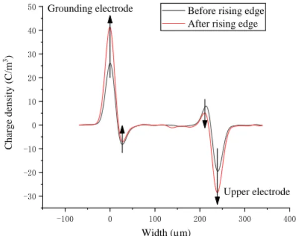
Fig. 8 shows the change in the space charge density at the rising and falling edges when the sample was stressed under square-wave voltage for 1 h. It can be seen that the space charge density at the electrode varies with the voltage amplitude. It increases with rising voltage and decreases with falling voltage. This phenomenon is similar to the capacitive charges at the initial time in Fig. 6.
-100 0 100 200 300 400 -30 -20 -10 0 10 20 30 40 50 Upper electrode Charge de nsity (C/m 3) Width (µm)
Before rising edge After rising edge Grounding electrode
(a) Change in the space charge density at the rising edge (from −15 to −30 kV/mm) -100 0 100 200 300 400 -40 -30 -20 -10 0 10 20 30 40 50 Upper electrode Charge de nsity (C/m 3) Width (µm)
Before falling edge After falling edge Grounding electrode
(b) Change in the space charge density at the falling edge (from −30 to −15 kV/mm)
Fig. 8. Change in the space charge density at the rising and
falling edges at 1 h.
What should be focused on is the heteropolar charges inside the samples. Interestingly, the changing trend of the space charge inside the XLPE is in contrast to that of the voltage amplitude. When the voltage amplitude decreases, the density of the space charge increases, whereas the density decreases when the voltage amplitude increases, as indicated by the arrows in Fig. 8.
Fig. 9 shows the change in the space charge density before and after the rising and falling edges when the sample was stressed under square-wave voltage for 2 h. The change trend is the same as in Fig. 8. The charge distribution at the other test time, such as 15 min, 30 min, 90 min, all show the same trend. Moreover, the space charges were measured under other voltages, for example, with the low-voltage level of -4 kV and high-low-voltage level of -8 kV, also showed the same changing law. The additional experimental data is not presented in the paper for concision.
-100 0 100 200 300 400 -40 -20 0 20 40 60 Upper electrode Charge de nsity (C/m 3) Width (µm)
Before rising edge After rising edge Grounding electrode
(a) Change in space charge density at the rising edge (from −15 to −30 kV/mm) -100 0 100 200 300 400 -40 -20 0 20 40 60 Upper electrode Charge de nsity (C/m 3) Width (µm)
Before falling edge After falling edge Grounding electrode
(b) Change in the space charge density at the falling edge (from −30 to −15 kV/mm)
Fig. 9. Change in the space charge density at the rising and
6 Besides the change in the space charge densities at the
rising and falling edges, whether the space charge changes during the constant voltage also needs to be evaluated. Fig. 10 shows the change in the heteropolar space charge density under low-stress level at 2 h. The test positions are 1, 6, 12, 18, 24, and 30. The graph shows that the space charge density barely changes. This means that the space charges have very low mobility when under constant electric field, thus the variation can scarcely be recognized with one period. This phenomenon is consistent with a previous report [19], which also showed that the space charge has a low accumulation speed when the voltage is constant.
-100 0 100 200 300 400 -30 -20 -10 0 10 20 30 Charge de nsity (C/m 3) Position (µm) 1 6 12 18 24 30
Fig. 10. Change in space charge at a low-voltage level of
−15 kV/mm applied for 2 h.
4. Discussion
4.1. Dynamic Mechanism of Space Charge at the Rising and Falling Edges
Schottky injection and the theory of hopping conductivity are generally used to explain the migration of space charges. However, in these processes, the rate of space charge change is low, and it takes a long time to complete the migration and accumulation of space charges. In this experiment, the time corresponding to the rising and falling edges is in the microseconds range. Therefore, these theories cannot be used to explain the experimental results.
According to the research theory of gas discharge, the forces acting on the space charge can be considered to explain for charge dynamics under the pulsed electric field. In the study of plasma, the gas discharge under the pulsed electric field shows the characteristics of stronger energy and more intense discharge, compared with that under the steady-state electric field, in the same way as solid insulation material. The relevant mechanism has been studied and some consensus has been reached [25, 26]. The studies indicate that the rapid change in an electric field accounts for the effect of the forces acting on charges intensified for gas discharge, and the pulsed electric field can work as an impulsive force [25]. Under the microsecond-level rising and falling time of the pulsed
electric field, this effect of the changing electric field force is more significant. Thus, we can analyze this phenomenon from the perspective of the changing electric field force, which means that the sudden change in the electric field may result in the unbalanced stress, which results in the transient movement of charges.
To clarify how the changing electric field impacts the space charge behaviour, the forces acting on the space charge need to be analysed firstly. The space charges are subjected to multiple forces inside the XLPE. To simplify the analysis, the forces are classified into two categories: electric field force and “material stress.” The former constitutes the force the space charge is subjected to under the electric field. The “material stress” includes the repulsive and attractive forces between the charges, the force of the material itself acting on the space charge, and other forces. The resultant of these forces is the “material stress.”
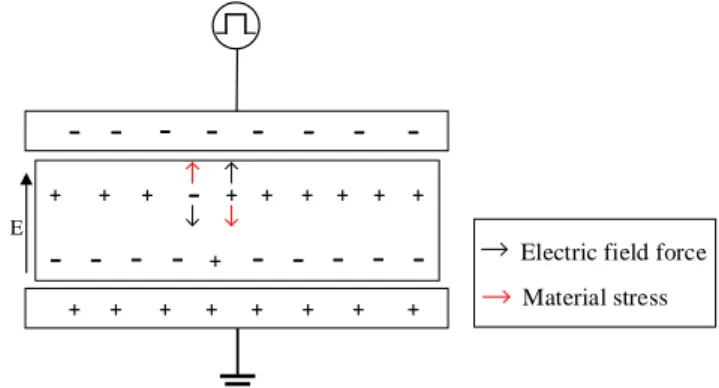
Under the polarization voltage, in addition to the significant accumulation of the heteropolar space charges in the XLPE, there exists some homopolar charges injected from the electrode, though the amount of heteropolar space charges is apparently more than that of homopolar space charges. The width of the interface charge peaks is approximately 30 µm with the current experimental resolution, so the homopolar space charge cannot be observed in the profiles. Therefore, the net space charge observed on the profiles is heteropolar. For example, near the cathode, there exists a large amount of positive charges attracted from the inside and possibly a small amount of negative charges injected from the cathode; however, the measured charge density is the net charge, whose amplitude is the positive charge density minus the negative charge density. Fig. 11 shows the space charge distribution and the illustration of the forces acting on the space charge in the constant-voltage stage, i. e., in the high-voltage level and the low-voltage level. The material stress is opposite to the electric field force, and the forces acting on the space charge is balanced; thus the space charge keeps stationary.
Fig. 11. Illustration of the forces acting on the space
charge in the constant-stage stage.
When the rising or falling edges comes, the balance between the electric field force and the material force is broken. The change in the force magnitude can be clearly seen in Fig. 12. The electric field force diminishes rapidly at the falling edge, while the material stress remains stable as the relative position between the charges does not change quickly. Therefore, the material stress is greater than the
- - - -
-
-- --
-
-
-
-+ + + + + + + + + + + +
-
+ + + + + + E Material stress Electric field forceelectrical field force. This leads positive charge migration into the XLPE near the cathode, and the negative charge is drawn off from the surface of the XLPE. Therefore, the positive charge density near the cathode increases at the rising edge. At the rising edge, the electric field force is enhanced while the material stress does not change immediately. Thus, near the cathode, the positive charge is drawn off, and the negative charge migrates into the XLPE. Subsequently, the positive charge density shows a decreasing trend. The same analysis method can also be applied to explain the change in the space charge density near the anode. Thus, voltage steps would unbalance the electrostatic forces, provoking a transient variation in the heterocharges by ionic transport, when the field strength suddenly varies.
(a) Change in the forces at the falling edge (from −30 to −15 kV/mm).
(b) Change in the forces at the rising edge (from −15 to −30 kV/mm).
Fig. 12. Schematic of the force change near the cathode at
the falling and rising edges.
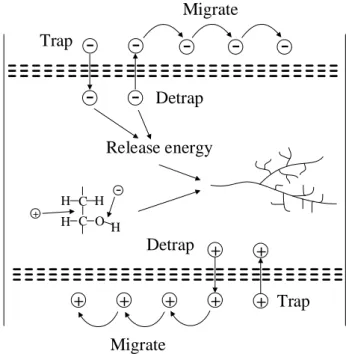
4.2. From Charge Dynamics to Treeing Initiation The most interesting experimental observation is the unusual phenomenon wherein the space charge density exhibits an opposite trend to the voltage amplitude. This may be closely related to the electrical tree initiation. The effect of the pulsed voltage will lead to the migration, injection, and extraction of space charges at the rising and falling edges, and charge migration involves trapping and detrapping processes. All these charge dynamic behaviours are accompanied with the release of energy [27]. The dissipated energy may break the chemical bonds of the
polymer and alter the microstructure, as hypothesized in electrical aging concepts, following a variety of possible mechanisms. The damage to the macromolecules produces a large number of free radicals and small molecular products. The free radicals generated have a catalytic effect on the degradation of the polymer, and in presence of residual molecular oxygen dissolved in the cable, it will lead to a wider range of degradation and eventually form a low-density zone. The electrons injected from the electrode ionize the molecular chains by collision in the low-density region [28]. A part of the energy released is converted to electromagnetic radiation, and a part of the energy is used to break more polymer molecules. This forms a hollow electrical tree channel, from which partial discharges can ultimately be triggered and accelerate the growth of the electrical tree. Finally, it will result in polymer breakdown. Fig. 13 illustrates the prospected effect of space charge behaviour on the electrical tree.
The electrons injected by field emission contribute to the electrical tree initiation if their energy exceeds a certain critical threshold [29]; the greater the total energy, the greater the damage to the dielectric. The detrapping of the
space charges will result in insulation material
depolarization, releasing a large amount of energy, like an avalanche, and causing electric field redistribution. Because of the pulsed nature of the electric field, the rates of injection, extraction, trapping, and detrapping of the space charge are reinforced, and the rates of energy conversion and release are also intensified, thus facilitating electrical tree generation as compared to that under a DC electric field alone.
Fig. 13. Schematic of space charge behaviour.
Comparing Fig. 9 and Fig. 10, charge mobility between the rising and falling edges is much larger than that at the constant-voltage stage. This phenomenon can be explained by force analysis. When the applied voltage is constant, space charge locates in stationary state, i.e., the electric field force and the material stress are almost the same; therefore, the charge mobility is very low. While at the rising and falling stages, the stress balance is broken and significant
- - - -
-
-- --
-
-
-
-+ + + + + + + + + + + + +
-
+ + + + + E Material stress Electric field force Electric field force Material stress+
-Material stress Electric field force Electric field force Material stress+
-Falling edge- - - -
-
-- --
-
-
-
-+ + + + + + + + + + + + +
-
+ + + + + Material stress Electric field force Electric field force Material stress+
-Material stress Electric field force Electric field force Material stress+
-Rising edge
+
--
-+
+
+
+
+
+
Migrate
Trap
Detrap
Trap
Detrap
Migrate
Release energy
C H H C H O H +-8 difference appears between the electric field force and the
material stress, which leads to quite large charge motion, corresponding to the dynamic behaviours analysed above.
Our experiment suggests dynamic behaviours of the space charges in XLPE at the rising and falling edges. However, current knowledge on the behaviour of space charges inside insulating materials is limited, and the influence of the parameters of the pulse voltage on the characteristics of the space charge is unclear, such as the slope of the rising and falling edges, and polarity of the impulse voltage. Hence, in future study, it is necessary to thoroughly explore the influence of space charge on the breakdown of insulation.
5. Conclusion
In this study, an experiment was conducted to investigate the dynamic behaviour of space charges in cable insulation when subjected to a pulsed electric field. The experimental results showed that at the rising and falling edges, the changing trend of the space charge inside the XLPE sample is opposite to the trend of the applied voltage. That is, when the voltage amplitude decreases, the space charge density increases, whereas the space charge density decreases with increasing voltage amplitude.
The effect of forces is used to explain this phenomenon. In the time interval under constant voltage, the two kinds of forces acting on the space charge, electric filed force and material stress, are balanced. At the rising and falling edges, this balance is broken, because the electric field force suddenly changes, while the material stress remains relatively stable, leading to the movement of space charges, i.e., injection, extraction, trapping, and detrapping.
This repeated dynamic behaviour can lead to the breaking of the chemical bonds on the polymer molecules, thereby inducing electrical tree initiation. Therefore, studying the
dynamic behaviour of space charges under
DC-superimposed pulsed electric field is important to reveal the breakdown mechanism of HVDC cable insulation under overvoltage conditions.
6. Acknowledgments
The research work of this paper was financed by the National Natural Science Foundation of China (Grant No.51907105) and the Shandong Provincial Natural Science Foundation (Grant No. ZR2019QEE013). I would like to express my heartfelt thanks to them.
7. References
[1] Liu, N., Zhou, C., Chen, G., Xu, Y., Cao, J., Wang, H.: ‘Model to estimate the trapping parameters of cross-linked polyethylene cable peelings of different service years and their relationships with dc breakdown strengths’, High Volt.,2016, 1, (2), pp. 95-105.
[2] Zhai, J. T., Li, W. K., Zha, J. W., Cheng, Q., Bian X. M., Dang Z. M.: ‘Space charge suppression of polyethylene induced by blending with ethylene-butyl acrylate copolymer’, CSEE J. Power Energy Systems, 2020, 6, (1), pp. 152-159.
[3] He, D. X., Meng, F. S., Liu, H. S., Li, Q. Q., Wang, X. R.: ‘The Influence mechanism of semiconductive material on space charge accumulation in HVDC cable accessory’, IEEE Trans. Dielectr.
Electr. Insul., 2019, 26, (5), pp. 1479-1486.
[4] Zheng, Y., Serdyuk, Y. V., and Gubanski, S. M.: ‘Space charge controlled electric field preceding inception of electric tree in XLPE at AC voltage’. Proc. Int. Conf. IEEE Properties and Applications of Dielectric Materials (ICPADM), Sydney, NSW, July, 2015, pp. 132-135.
[5] Wu, S. L., Yang, Q., Shao, T., et al.: ‘Effect of surface modification of electrodes on charge injection and dielectric characteristics of propylene carbonate’, , 2020, 5, (1), pp. 15-23.
[6] Li, C. Y., Lin, C. J., Yang, Y., Zhang, B., et al.: ‘Novel HVDC spacers by adaptively controlling surface charges – Part II: Experiment’, IEEE Trans. Dielectr. Electr. Insul., 2018, 25, pp.1250-1260.
[7] Du, B. X., Han T., Su, J. : ‘Electrical tree characteristics in silicone rubber under repetitive pulse voltage’, IEEE Trans. Dielectr. Electr.
Insul., 2015, 22, (2), pp. 720-727.
[8] Liu, H., Zhang, M., Liu, Y., Xu X., et al.: ‘Growth and partial discharge characteristics of DC electrical trees in cross-linked polyethylene’, IEEE Trans. Dielectr. Electr. Insul., 2019, 26, (6), pp. 1965-1972.
[9] Han, T., Du, B.X., Ma, T.T., et al.: ‘Electrical tree in HTV silicone rubber with temperature gradient under repetitive pulse voltage’,
IEEE Access, 2019, 7, pp. 41250-41260.
[10] Hammarström, T. J. Å., Bengtsson, T., Gubanski, S. M.: ‘Partial discharge characteristics of electrical treeing in XLPE insulation exposed to voltages of different rise times’, Proc. Int. Conf Electrical Insulating Materials (ISEIM), Toyohashi, 2017, pp. 407-410. [11] Zhang, Y., Lewiner, J., Alquie, C., et al.: ‘Evidence of strong
correlation between space-charge buildup and breakdown in cable insulation’, IEEE Trans. Dielectr. Electr. Insul., 1996, 3, (6), pp. 778-783.
[12] Zhang, Y. X., Zhang, L., Zhou, Y. X., et al.:“Electrical treeing behaviors in silicone rubber under impulse voltage considering high temperature”, Plasma Science and Technology, 2018, 25, (5), pp. 054012(1-8).
[13] Liu, Y., Cao, X. L., Chen, G.: ‘Electrical tree initiation in XLPE cable insulation under constant DC, grounded DC, and at elevated temperature’. IEEE Trans. Dielectr. Electr. Insul., 2018, 25, (6), pp. 2287-2295.
[14] Wang, Y. N., Li, G. D., Wu, J. D., Yin, Y.: ‘Effect of temperature on space charge detrapping and periodic grounded DC tree in cross-linked polyethylene’, IEEE Trans. Dielectr. Electr. Insul., 2016, 23, (6), pp. 3704-3711.
[15] Du, B. X., Li, A.: ‘Effects of DC and pulse voltage combination on surface charge dynamic behaviors of epoxy resin’, IEEE Trns.
Dielectr. Electr. Insul., 2017, 24, (4), pp. 2025-2033.
[16] Du, B. X., Liu, Z. X., Xiao, M. : ‘Effect of pulse duration on surface charge of direct-fluorinated polyimide films’, IEEE Trans. Dielectr.
Electr. Insul., 2015, 22, (6), pp. 3481-3487.
[17] Wang, S., Li, A., Xing, Y., er al.: ‘Surface potential and breakdown characteristics of epoxy/AlN nanocomposites under DC and pulse voltages’, IEEE Trans. Appl. Superconductivity,2019, 29, (2), pp. 1-5. [18] Fukuma, M., Teyssedre, G., Laurent, C., et al.: ‘Millisecond time-range analysis of space-charge distribution and electroluminescence in insulating polymers under transient electric stress’, J. Appl. Phy., 2015, 98, (7), pp.093528(1/11).
[19] Hozumi, N., Teyssedre, G., Laurent, C., et al.: ‘Behaviour of space charge correlated with electroluminescence in cross-linked polyethylene’, J. Phys. D: Appl. Phys., 2014, 37, (9), pp. 1327-1333.
[20] Liu, Y., Wu, G., Gao, G., et al.: ‘Progress of research into the polyimide insulation failure mechanism under square impulse stress’:
High Voltage Apparatus, 2016, 52, (7), pp. 10-18. (in Chinese)
[21] Wang, X., Shu, Z. H., Duan, S. J., et al.: ‘Space charge accumulation property in XLPE under applied voltage of square wave’, High Volt.
Eng., 2020, 46, (2), pp. 634-639. (in Chinese)
[22] Liu, H., Li, Y. D., Zhang, M. J., et al.: ‘Electrical tree initiation characteristics under DC-impulse composite voltages in XLPE’, High
Volt. Eng., 2019, 45, (8), pp. 2637-2643.
[23] Meunier, M., Quirke, N., Aslanides, A.: ‘Molecular modeling of electron traps in polymer insulators: Chemical defects and impurities’,
J. Chem. Phys., 2001, 115, (6), pp. 2876-2881.
[24] He, D. X., Wang, X. R., Liu, H. S., et al.: ‘Space charge behavior in XLPE cable insulation under ac stress and its relation to thermo-electrical aging’, IEEE Trans. Dielectr. Electr. Insul., 2018, 25, (2), pp. 541-550.
[25] Kasashima, Y. J., Uesugi, F.: ‘Impulsive force phenomenon of electric field stress causing serious particle contamination in plasma etching equipment’, Jpn. J. Appl. Phys. 2014, 53. pp. 110308, [26] Zhang, Y. T., Wang, Y. H.: ‘Modeling study on the effects of pulse
rise rate in atmospheric pulsed discharges’, Phys. of Plas., 2018, 25, (2), pp. 023509.
[27] Dong, G. J., Li, Q. M., Liu, T., et al.: ‘Finite-element analysis for surface discharge on polyimide insulation in air at atmospheric pressure under pulsed electrical stress’, High Volt., 2020, 5, (2), pp. 166-175.
[28] Matsui, K., Tanaka, Y., Takada, T., et al.: ‘Space charge behavior in low-density polyethylene at pre-breakdown’, IEEE Trans. Dielectr.
Electr. Insul., 2005, 12, (3), pp. 406-415.
[29] Tanaka, T., Greenwood, A.: ‘Effects of charge injection and extraction on tree initiation in polyethylene’, IEEE Trans. Power