HAL Id: hal-00669391
https://hal.archives-ouvertes.fr/hal-00669391
Submitted on 13 Feb 2012
HAL is a multi-disciplinary open access
archive for the deposit and dissemination of
sci-entific research documents, whether they are
pub-lished or not. The documents may come from
teaching and research institutions in France or
abroad, or from public or private research centers.
L’archive ouverte pluridisciplinaire HAL, est
destinée au dépôt et à la diffusion de documents
scientifiques de niveau recherche, publiés ou non,
émanant des établissements d’enseignement et de
recherche français ou étrangers, des laboratoires
publics ou privés.
Combining SysML and AADL for the Design, Validation
and Implementation of Critical Systems
Pierre de Saqui-Sannes, Jérôme Hugues
To cite this version:
Pierre de Saqui-Sannes, Jérôme Hugues. Combining SysML and AADL for the Design, Validation and
Implementation of Critical Systems. ERTS2 2012, Feb 2012, Toulouse, France. pp.117. �hal-00669391�
Combining SysML and AADL for the
Design, Validation and Implementation of Critical Systems
Pierre de Saqui-Sannes1,2, Jérôme Hugues1
1: Toulouse University/ISAE at 1 place Emile Blouin, 31056 Toulouse, France 2: CNRS ; LAAS ; 7 avenue du Colonel Roche, F-31077 Toulouse, France Université de Toulouse ; UPS, INSA, INP, ISAE ; LAAS ; F-31077 Toulouse France
Abstract: The realization of critical systems goes through multiple phases of specification, design, integration, validation, and testing. It starts from high-level sketches down to the final product. Model-Based Design has been acknowledged as a good conveyor to capture these steps. Yet, there is no universal solution to represent all activities. Two candidates are the OMG-based SysML to perform high-level modeling tasks, and the SAE AADL to perform lower-level ones, down to the implementation. The paper shares an experience on the seamless use of SysML and the AADL to model, validate/verify and implement a flight management system.
Keywords: Modeling Process, Real-Time, SysML, AADL, Model Verification, Model-Based Code Generation. 1. Introduction
Model-Based Engineering (MBE) has emerged as a key set of technologies to engineer complex systems. An MBE approach associates modeling languages and tools to a rigorous design process from requirement elicitation to design, implementation, integration and testing. The objective is to come up with a seamless process that bridges system and software engineering. The paper proposes a seamless process for critical embedded systems relying on SysML and AADL. SysML [1] is the System Modeling Language standardized by the Object Management Group. AADL [2] is the Architecture Description Language supported by the SAE AS2-C working group. SysML and AADL provide two distinct views of the same system. A SysML model furnishes a high-level view for the system engineer. AADL makes it possible to build up a lower-level view for the engineer in charge of the implementation as an embedded system, combining hardware, operating system and code implementing all functions. In other words, SysML supports the early stages of system engineering, while AADL supports the design, and analysis of embedded systems. In the context of critical systems, SysML and AADL are complementary. Again, our objective is to reduce the gap between system engineers and architects. The rationale of the process proposed by the paper is as follows: the real-time variant of SysML named AVATAR enables requirement capture, use-case and scenarios analysis, and architectural/behavioural design using blocks and state machines. An AVATAR model may be debugged and formally verified using TTool [3] and UPPAAL [5]. Once approved by the system engineer team, the AVATAR model is transformed into an AADL model that maps system blocks onto execution resources and details behaviours so as to achieve schedulability or dimensioning analysis using Ocarina [2].
The paper is organized as follows. Section 2 defines a process for critical systems design. Section 3 introduces the case study: a longitudinal flight management system. Section 4 applies AVATAR and TTool to the case study. Section 5 applies Ocarina to the AADL model derived from the AVATAR model. Section 6 surveys related work. Section 7 concludes the paper and outlines future work.
2. Process
SysML and AADL are notations, not methods. Our first concern is to introduce a method for embedded system design.
2.1. Requirement Capture
A requirement diagram defines a tree-structure of general requirements, refine them into technical requirements, and connect requirements to stereotyped test cases that we term as “properties” by reference to the properties used to formally verify design diagrams.
A model abstracts a real system; it is valid under a set of assumptions that apply to the system itself as well as to the language, tools and method in use.
2.3. Analysis
A use-case diagram characterizes the system by its boundary, the functions (or use-case) it should implement, and the set of external actors it interacts with. Scenarios expressed by sequence diagrams document the use cases.
2.4. Design
A block diagram defines the static architecture of the system as a set of blocks internally defined by extended finite state machines. The design diagrams are formally checked against logical and timing errors. The benefits of formal verifications will be optimal if the design step is incremental.
The design step includes two main sub-steps that respectively output a functional and an organic architecture. The former defines functional and communicating blocks that describe high-level interactions between abstractly described functions. The latter describes a physical architecture, which serves as starting point to create the AADL architecture. The designer maps each function to actual execution resources. This is the design objective of the AADL language.
2.5. Detailed Design
AADL is a component-oriented modeling framework. A model is a set of interconnected component instances. A component instance is one particular incarnation of a component type that defines its interface (parameters, ports, requirement to access to other elements), and the corresponding component implementation that refines its internals.
AADL has been defined so that a software engineer can use the vocabulary and concepts of his/her domain. A component type is categorized by its nature: software (thread, subprogram, process), hardware (processor, device, bus, memory) or hybrid (system, abstract). A component is defined by a type, an implementation and a set of properties attached to its actual semantics or to resources requirements. Thus, one may model a set of tasks, connect them to match data flow requirements as part of a process implementation, and bind this process to an operating system, supported by a processor. This includes non-functional properties, such as actual data type representation, worst-case execution time, and priority ranges.
2.6. Detailed analysis
The AADL language is supported by a large variety of analysis tools for scheduling, resource dimensioning, model checking, security, and fault-propagation analysis, just to mention a few. Most of them are available as Open Source software [2]. Actually, SysML and AADL provides two distinct views of the same system: one high-level view for the system engineer, one lower-level view to the software engineer, in charge of the implementation as a full-fledged embedded systems.
3. Case Study
The Longitudinal Flight Management System (LFMS) allows the pilot to put the plane in the right direction according to the altitude and therefore to manage risings and descents. The LFMS is active throughout the entire flight, including take off and landing. The LFMS does not manage yaw angle. It solely commands the elevators to control the pitch position. It also triggers alarm lights for the pilot.
Assuming an execution cycle of 5ms, the LFMS is connected to functions as various as flight parameters computation, flight command management, automatic pilot and alarms.
The development of a LFMS has to abide to a stringent development process. The DO-178B standard mandates various activities to be performed to achieve certification of each function and then airworthiness of the full aircraft. One key objective is to ensure traceability from high-level requirements to actual implementation, and between all intermediate artifacts. Next revision of DO-178 will allow MBD as part of the engineering process. In the following, we illustrate how traceability between all model elements can be carried out, while allowing for early validation of the system at each step, and then its full generation.
4. LFMS Modelling in Avatar
The process defined in section II starts with requirement capture. Three requirement diagrams respectively address the inputs (sensors, human operator), the outputs (display, actuators) and the LFMS functions. Figure 1 identifies a set of general requirements attached with the LFMS’s inputs and derives technical requirements from general ones.
Figure 1 – Requirement Diagram Figure 2. Use-case Diagram
The AVATAR model developed from elicited requirements is valid under a set of assumptions categorized by their origin (system, language, tools, process), their type (e.g. “not implemented function”) and their description in plain text. The model discussed in the paper thus ignores failures and maintenance operations.
Figure 1 attaches the UnexpectedIncidenceAlarm property to the Incidence requirement node. The property will be used to verify design diagrams. The use-case diagram depicted Figure 2 conveys a functional view of the system and identifies which other part of the plane the LFMS interacts with. For space reasons, the sequence diagrams that document the uses cases are not provided in the paper.
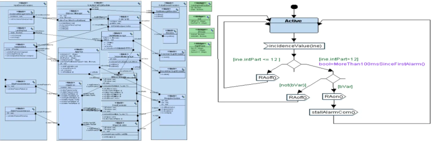
Figure 3 depicts the architecture of the LFMS system as a set of block instances that communicate via ports. The diagram merges block instances and types definitions (attributes and methods). The above architecture connects the system to input and output devices emulators, thus making the global system a closed one, an important step for simulation and verification. Each block in the architecture has a behavior described by an extended state machine. Figure 4 depicts the state machine associated with the stallAlarm component. This alarm is triggered whenever the incidence angle is greater that 12°.
Figure 3. Block Diagram (organic architecture) Figure 4. State Machine Diagram
The design model made of the architecture and state machines is now ready for debugging using the simulator integrated to the TTool toolkit. TTool generates simulation traces in terms of scenarios that identify how block instances internally evolve and communicate with one another. Also, TTools graphically animates the state machines and makes it easy for the designer to connect simulation results to the original AVATAR model. Usual functions like scenario replay and statistics are also available.
Thus, TTool includes a model simulator. It also offers a press-button interface to the UPPAAL model checker via the connection it maintains between the AVATAR model and the timed automata specification derived from that model. Formal verification search for deadlocks and verifies reachability as well as liveness properties on the states and actions of the protocol machines. To decide whether some action is reachable or not, or to study the liveness of that action, it suffices to right click on the symbol of that action. The UPPAAL model checker is invoked with the corresponding CTL formula, and the result of reachability / liveness properties is displayed by TTool. This way the use of TTool does not require preliminary knowledge of CTL or other logics.
Formal verification with TTool also relies on observers. An observer is a UML object manually or automatically [14] included in the model of the system in order to drive formal verification. Given an observer O checking an AVATAR model against requirement R, O must behave as follows: each time R is violated, a transition label in the reachability graph must unambiguously identify R’s violation. A quick search of requirement violation labels thus enables identification of unmet requirements.
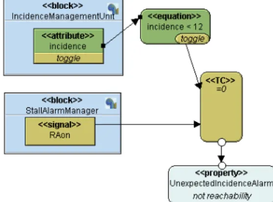
Whatever the verification approach, one needs to express the properties to be verified. AVATAR reuses SysML parametric diagram to pictorially depict properties. As an example, Figure 5 uses a parametric diagram and the TEPE language to depict the UnexpectedIncidenceAlarm property.
Figure 5. TEPE parametric diagram
5. AADL and Ocarina
Once the high-level design has been validated, the engineer team may focus on its implementation on a target platform. Thus, one needs to map SysML model elements onto actual implementation blocks. SysML design diagrams define functional blocks, their interface and their behavior as state machines.
The next step is to bind all these functions to execution resources. To preserve the properties validated on the AVATAR model, and to ensure a seamless process, we propose to use AADL to model all these parts, and then derive an implementation. We now sketch this modeling process, using AADLv2 standard notations.
AADLv2 has facilities to support incremental modeling and validation. Our entry point is a set of SysML diagrams, blocks with interfaces. This is equivalent to AADLv2 abstract component category. An abstract component simply indicates the intent of a function; it is later refined onto a concrete component category (e.g. a thread, a process or a device).
It is the exact counter part of a SysML block. For all blocks, we define one abstract component type with the same interface, and derive some non-functional properties from the state machines (modes, data types, timing requirement, etc.). This one to one mapping may be automated. Besides, it ensures a strict boundary between the SysML world, and the AADL one, with a possibility to do a reverse mapping. This feature is highly beneficial for ensuring traceability.
The second feature from AADL we use is component refinement. Following object-oriented principles, one may refine a type and extend it. In the case of an abstract component type, to derive a concrete type, and in the case of concrete elements to build an inheritance tree, we refine interfaces to go from an opaque type such as “pressure” to an actual type such as 32-bits floating type. Each refinement builds a new intermediate component type. This refinement mechanism allows the designer to navigate through its hierarchy of types, each of which illustrates one design choice.
AADL defines annex languages to model specific concerns such as Integrated Modular Avionics (IMA) systems, or their behavior as timed state machines as part of the AS5506/2 standard. The IMA annex is used to map functions to execution resources in the context of avionics systems following the ARINC653 standard runtime. The behavior annex is used to capture the behavior of a component. In our context, it is derived from the SysML automata.
This iterative process will ultimately converge with the binding of actual source code implementing each function to AADL subprograms component type, the definition of threads, devices supporting interaction with operators, sensors and actuators, and the configuration and binding of these threads to a runtime environment.
It is important to mention that AADL models may be validated at each refinement: first when combining abstract types, then when performing refinements, and finally when binding refined modules to the execution platform. Validation is syntactic and semantic: we ensure that the architecture being modeled is notionally sound. Depending on the properties used, the validation may also apply to the system’s behavior (for instance to check composition of blocks with respect to the use of a particular interconnection bus); or to its schedule.
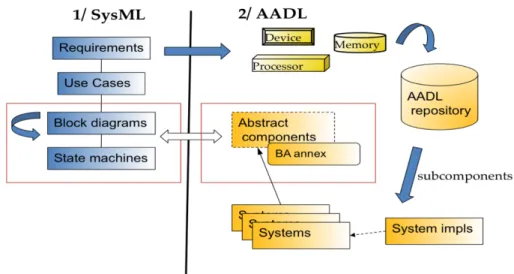
From this set of principles, we instantiated the process as follows (see figure 6):
1. From the set of requirements, a set of AADL components can be defined as potential building blocks for the system. Information about the application domain, such as the avionics domain is likely to force the choice of particular CPU or network architecture.
2. SysML Block diagrams are mapped onto AADL abstract components; connections between SysML block diagrams are reflected in the interconnection of the AADL blocks.
3. SysML State machines are mapped onto AADL behavioral annex elements, and directly bound to the corresponding AADL abstract component. This strong link between the two elements is important to ensure interfaces between both models match.
From this step, we may now follow on a more traditional modeling processing based only on the AADLv2:
1. Abstract components are refined to concrete component types (e.g. devices, processors, threads, …). Components are selected from a repository of AADL models, det;
2. These components are combined in a bottom-up fashion to build all terminal elements, sub-systems and finally systems. This combination of models follows the instantiation process as defined in the AADLv2 standard.
Figure 6: Integration between SysML and AADL
We modeled a subset of this case study as a proof of concept, and applied checks we discussed in previous work [11]. They allow us to check additional legality rules to ensure the system does respect modeling patterns for avionics system and IMA.
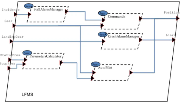
Figure 7: LFMS in AADLv2
Figure 6 represents the threads forming the software part of the LFMS. The process (enclosing box) has input and output ports modeling data flows from sensors or to actuators. Each thread is a refinement of the corresponding abstract function imported from the SysML block diagram. This graphical model has been derived from the textual AADLv2 representation we used to model the full system. The textual notation is more verbose, and allows for finer traceability between model elements (ports, threads, etc.). It is preferred to model safety-critical system so as to maximize traceability.
Several functions compute outputs from the same set of inputs (e.g. speed or pressure). Besides, these are simple computations based on physical laws. To reduce overhead, a design decision is to merge functions in the same thread. This is the role of the “ParameterCalculator” that merges slope, pressure and altitude computation. Alarm managers are not merged. Although they also implement simple computations, it is safer to leave them separated, as each one raises a separated alarm signal.
Once the model has been validated, once can focus on its implementation. Two options are available: implement each function directly as C or Ada programs; or model them using Simulink [13] or SCADE [14]. In both cases, these descriptions can be bound to the AADL model by pointing leaf model elements (modeled as AADL subprograms) to the corresponding model or source code artifact. Then the Ocarina code generator can generate the complete application: process bound to an operating system, thread configured using model non-functional properties and then thread execution pattern for periodic or sporadic threads calling user-defined code or models [12].
These validation and code generation steps help ensuring the model respects all domain-specific constraints for critical systems, and traceability between model and source code. For now, the code generated follows stringent guidelines for space and avionic systems, ensuring it can be later fully tested following code coverage criteria such as MC/DC for avionics system, but also worst-case evaluation techniques, or symbolic execution.
6. Related Work
Authors in [6] discuss the use of SysML, UML and model-checking for space applications. Authors reuse the process defined by the European Cooperation for Space Standardization body. For each step, one may easily find a counter part in the early stages of the process introduced in Section II. Like the UML tool Rhapsody, TTool is interfaced with UPPALL, but with improved user-friendliness. By contrast, the detailed design and schedulability analysis achieved using AADL and Ocarina have no counterpart in this work.
As suggested by the acronym, AADL fundamentally address architectural issues, which means design issues. AADL does not provide any notation for the requirement capture and analysis phase. Therefore, the notations used as front end to the design step in AADL are numerous.
Authors in [9] leaves requirement capture and analysis apart the AADL modeling process. Temporal formal verification is achieved at the AADL level where the approach proposed in this paper enables both earlier detection of design errors, and detailed verification. Early verification is a key requirement to reduce design cost.
Finally, [8] outlines a life cycle that sequentially uses SysML, AADL and UML, giving some hints at how to combine them. Contrary to their approach, the process we propose provides an implemented solution, applied to a full case study as a proof-of-concept. It supports formal verification of SysML-AVATAR design diagrams and starts using AADL at the detailed
design step. Code generation is not delegated to a UML tool, but fully integrated to the AADL part of the process. The approach illustrated in the paper further introduces schedulability analysis, which is not addressed by the authors.
7. Conclusions
The paper proposes a global model-based approach for the design, validation and implementation of critical embedded systems, combining standardised and tooled SysML (with AVATAR real-time profile) for system level modelling, requirement capture, use case and scenarios analysis, architecture description, and AADL at software level down to implementation. A flight management system serves as running example.
SysML-AVATAR and AADL are two complementary modeling languages supported by TTool and Ocarina, respectively. SysML/AVATAR enables requirement capture, use-case and scenario driven analysis, and verification-centric design. AADLv2 accepts a preliminary design from TTool and refines it terms of architecture and behaviour. The resulting AADL model is also the basis for reachability analysis and code generation, taking as input a more detailed view of the system. A bridge between these two notations is introduced. V&V process includes model-checking of SysML activities using UPPAAL, as well as code generation, scheduling analysis, and model coverage using Ocarina.
Combining the two notations allow for a combined process that merges high-level modeling consideration and low-level modeling notation geared towards implementation. Seamless integration has been defined through carefully chosen SysML diagrams and their AADL counterparts.
Ongoing developments include automatic translation of AVATAR models into AADL. We also plan to extend TTool and Ocarina libraries of patterns that will contribute to achieve model reusability, and methodological assistants to ease transitioning from SysML to AADL. Extending the number of SysML diagrams as inputs must be contemplated, based on existing experiments around the SysML. This is subject to further study. Finally, testing is a key issue [7] not addressed in the paper. We plan to develop test-case generators for SysML and AADL.
Acknowledgements
Ludovic Apvrille has developed TTool and co-designed the AVATAR language with the first author. Daniel Knorreck has contributed on TEPE’s definition and TTool’s development. The case study reuses fragments of a SCADE model developed by Frédéric Camps and ISAE students. Ocarina is a joint-project between ISAE, Telecom ParisTech and ESA. It is also part of the TASTE toolchain.
References
[1] R. Behtaji, S. Nejati, L. Briand, B. Selic, An AADL-Based SysML Profile for Architecture level Systems Engineering: Approach, Metamodels, and Experiments.
[2] SysML, http://www.sysml.org.
[3] AADL, http://www.aadl.info/aadl/currentsite/. [4] http://labsoc.comelec.enst.fr/turtle/ttool.html.
[5] D. Knorreck, L. Apvrille, P. de Saqui-Sannes, “TEPE: A SysML Language for Timed-Constrained Property Modeling
and Formal Verification”, UML/FM 2010, Shangai, China, November 2010.
[6] http://www.uppaal.com/
[7] E. C. da Silva and E. Villani, “Integrando SysML e model checking para v&v de software crítico especial”, Brasilian Symposium on Aeropspace Engineering and Applications, São José dos Campos, SP, Brazil, Sept. 2009.
[8] R. F. Araujo, V.H. Durelli, M. Delamaro, J. Maldonado, “Geração de Dados de Teste a Partir de Modelos de Sistemas
Embarcados: Uma Revisão Sistemática”, Brazilian Symposium on Formal Methods, Gramado, RS, Brazil, 2009.
[9] J. D. McGregor, “Modeling Software, Journal of Object Technology”, Vol. 8, No.1, Jan-Feb 2009.
[10] T. Correa, L.B Becker, J-M Farines, J-P.Bodeveix, M.Filali, F.Vernadat, “Supporting the Design of Safety Critical
Systems Using AADL”, UML and AADL 2010, Oxford, United Kingdom, March 2010.
[11] http://ocarina.enst.fr/
[12] O. Gilles, J. Hugues, Jérôme “Expressing and enforcing user-defined constraints of AADL models”. UML and AADL 2010, Oxford, United Kingdom, March 2010.
[13] J. Delange, J. Hugues, L. Pautet, D. De Niz, Diosisio,“A MDE-based process for the design, implementation and
validation of safety critical systems”. UML and AADL 2010, Oxford, United Kingdom, March 2010.
[14] Simulink, http://www.mathworks.com [15] SCADE, http://www.esterel-technologies.com
[16] R. Behtaji, S. Nejati, L. Briand, B. Selic, An AADL-Based SysML Profile for Architecture level Systems Engineering: Approach, Metamodels, and Experiments, Simula Research Laboratory, February 2011.