Publisher’s version / Version de l'éditeur: ASHRAE Transactions, 98, 2, pp. 307-318, 1992
READ THESE TERMS AND CONDITIONS CAREFULLY BEFORE USING THIS WEBSITE. https://nrc-publications.canada.ca/eng/copyright
Vous avez des questions? Nous pouvons vous aider. Pour communiquer directement avec un auteur, consultez la première page de la revue dans laquelle son article a été publié afin de trouver ses coordonnées. Si vous n’arrivez pas à les repérer, communiquez avec nous à PublicationsArchive-ArchivesPublications@nrc-cnrc.gc.ca.
Questions? Contact the NRC Publications Archive team at
PublicationsArchive-ArchivesPublications@nrc-cnrc.gc.ca. If you wish to email the authors directly, please see the first page of the publication for their contact information.
NRC Publications Archive
Archives des publications du CNRC
This publication could be one of several versions: author’s original, accepted manuscript or the publisher’s version. / La version de cette publication peut être l’une des suivantes : la version prépublication de l’auteur, la version acceptée du manuscrit ou la version de l’éditeur.
Access and use of this website and the material on it are subject to the Terms and Conditions set forth at
Full-scale experimental results on the mean and turbulent behavior of
room ventilation flows
Zhang, J. S.; Wu, G. J.; Christianson, L. L.
https://publications-cnrc.canada.ca/fra/droits
L’accès à ce site Web et l’utilisation de son contenu sont assujettis aux conditions présentées dans le site LISEZ CES CONDITIONS ATTENTIVEMENT AVANT D’UTILISER CE SITE WEB.
NRC Publications Record / Notice d'Archives des publications de CNRC: https://nrc-publications.canada.ca/eng/view/object/?id=db2e27b7-2c7b-4dbd-ade0-a56f94f11992 https://publications-cnrc.canada.ca/fra/voir/objet/?id=db2e27b7-2c7b-4dbd-ade0-a56f94f11992
Full-scale experimental results on
the mean and turbulent behavior
of room ventilation flows
Zhang, J.S.; Wu, G.J.; Christianson, L.L.
NRCC-35975
A version of this document is published inASHRAE Transactions, 98(2), ASHRAE Annual Meeting (Baltimore,
MD, USA, July-27-92), pp. 307-318, 92:
The material in this document is covered by the provisions of the Copyright Act, by Canadian laws, policies, regulations and international agreements. Such provisions serve to identify the information source and, in specific instances, to prohibit reproduction of materials without written permission. For more information visit http://laws.justice.gc.ca/en/showtdm/cs/C-42
Les renseignements dans ce document sont protégés par la Loi sur le droit d’auteur, par les lois, les politiques et les règlements du Canada et des accords internationaux. Ces dispositions permettent d’identifier la source de l’information et, dans certains cas, d’interdire la copie de documents sans permission écrite. Pour obtenir de plus amples renseignements : http://lois.justice.gc.ca/fr/showtdm/cs/C-42
BA-92-2-3
FULL-SCALE EXPERIMENTAL RESULTS
ON THE MEAN AND TURBULENT BEHAVIOR
OF ROOM VENTILATION FLOWS
O[[_コャャセセセZセセMセM
_セセセイ⦅イ@
セャ。エセGZG⦅セセLTshrae@
G.J. Wu, Ph.D, P.E.
Member ASHRAEL.L. Christianson, Ph.D, P.E.
Member ASHRAE ABSTRACTExperiments
were
condua«i in a jidl-scale tt!St room (18 by 24 by 8ft [5.5 by 7.3 by 2.4 m])for both isothermal and nonlsothennal conditions. Bas«/ on the experimental data, this paper discusstiS (1) the statisticalfeatlll"t!S of air velodty fluctuations Including probabiUty density fonctions and energy speara; (2) the observed airflow patterns; and(3) the spatial distributions of mean velodty, turbulence Intensity, kinetic energy of turbulence, and mean tempera-ture. Spedal attention Is paid to 1M tdfects of the dflfuser air velodtitiS and internal heat loads on the
flow
charac-teristics and to the dlffertmoes between the dflfuser jet region and the occupied region. '1he detailed experimental data are also useful for evaluating and improving numer-ical simulotion models of room air motion.INTRODUCTION
Understanding room air distribution is essential to the design of ventilation systems and control of room thermsl and air quality conditions. Air velocities in occupied zones of a room cfuectly affect the them.l comfort of occupants.
The movement of air within a room also affects the release rate of hest and contsmin•nts from sources and determines how the hest and contaminants distribute, thus affecting the
air quality available to the occupants. In addition, proper
air distribution can reduce the ventilation rate necessary for removing air contsminants and moisture, thus reducing building energy consumption. Study of room air distribu-tion is important to many applicsdistribu-tions, including commer-cial and residential rooms, clean room manufacturing, electronic and computer rooms, biomedical research, hospital disease control, and greenhouse and animal agriculture (Christianson 1989).
Room air distribution is a complicated process. Resear-chers have developed a limited understanding through experimental measurements and numerical modeling. Research efforts have concentrated on high ventilation rate conditions (fully turbulent flow), isotherms! conditions (no internal hest loads), limited, if any, internal obstructions (no furniture and equipment), and simple room geometries to simplify the problem. Realistic room ventilation flow
usually has multiflow festures, including high and tow turbulence, which incresse the complexity of both physical and msthematical modeling. Physical modeling is also complicated by the difficulty of air velocity measurements since low air velocities (
<
SO fpm [0.25 m/s]) are in-volved.Methods commonly used for investigating room air
distribution are filll-scale measurements, similitude model study, and numerical simulations. Measurements in full-scale rooms are ess...,tialto the understanding of room flow behavior, and the evaluations of indirect techniques such as similitude studies and numerical models, and are currently the only assured method of evaluating room airflow. However, it is generally expensive and inconvenient to conduct filll-scale experiments, and the results can only be
applied to rooms that are identical (at least very similar) to the prototype studied.
Similitude study involves experiments in a reduced-scale-model room and extrapolations of the results from
this model room to its prototype. More important,
simili-tude makes it possible to extrapolate experimental findings to a variety of rooms with similar geometry without the
need for physical modeling of every prototype. The application of similitude to room airflow is limited by our knowledge of proper acaling methods for extrapolating the data. Knowledge of the reponal characteristics of the room airflow, including its twbulMt behavior, is necessary to the development of the acaling theory.
Numerical simulation involves msthematically model-ing the room airflow and numerically solving the model. While complicated, it is in principle the most generalized method and thus is most convenient for predicting room airflows. However, advances in numerical modeling are limited by the lack of compatible, adequately detailed experimental dats for model evaluation and by the lack of knowledge of room airflow characteristics, especially the turbulent flow features.
The objectives of this research were to improve the understanding セヲ@ the mean and turbuiMt behavior of realistic room ventilation flows and provide experimental
dats for evaluating and improving numerical simulation models of room air motion.
Jlansbun セAAQQ@ •. J'll,D_, セN。@ research オッッ」ゥ。Nエ」NセMQQAセ@ ャAAャャゥャAAセMセセ@ r」ッセセ@ • NNmセセjセ・ウ」。イ」ィ@ CouncU .. !!i . .can.lk,
セoエエFwFLBッゥゥャ。イゥッN@ G. Jtlf
wu;
pャゥZoセ[@·p;s;;
ii
an usistant professor at the Univenity of W11consin,MadisOn:LeSJleL.Cbristianson,
Ph.D., P.!!., is a professor and director of the Bioenvitonmcntall!ngineering Resesrch Labontory, Univenity of Illinois, Urbana.UTERA TURE REVIEW
The following review is not nieant to be exhaustive but
to give a clesr picture of the cumnt ststua of full-scale studies of room ventilation flows.
Studies Conducted In the U.S.
Straub and Chen (1957) conducted more than 300 heatina and cooling tests with a number of different diffusers, diffuser locations, airflow rates, return locatioas, and room heat loads. These data are valuable and have resulted in empiricsl equations for predictina the trsjectory and centerline velocities of diffuser air jets that are still
widely \lied (ASHRAE 1989).
Nevins and Miller (1972) studied room air movement
extensively. They defined the air diffusion performance index (ADPI) to relste room air distribution to bumsn
comfort. They showed that ADPI could be relsted to room
air diffuser clwacteristics, room size, and cooling load.
Hart and Int-Hout (1980) tested a perimeter linesr air
diffuser in a full-scale model office building and concluded that linesr air diffusers can aatisfy office building comfort needs without the oeed for a hat source on exterior window walls to prevent downwad drafts from movina from the window to the occupied ZDDe.
Fitzner (1981) conducted full-scale ュッ、・ャセ@
for an air-conditioned room. Filmer showed that the airflow inside the room was mainly influenced by the form and location of the air diffuser, lbe air exchange rate, the cooling rate (which affects the セィ・ョョ。セ@ buoyancy effect), and the direction of introduced airflow with respect to pvity. The influence of air returns usually could be neglected. He also compared three types of diffusers in terms of aas concentration versus baght and distance from
a gas source.
Timmons (1984) \lied smoke to observe the ·flow pattern in a prototype buildina with cross-sectional
dimen-sions of25.3 by 6.7 ft(7.72 by 2.05 m). The fluid motion near the room exhaust approximated potential flow, while most of the room airflow was biahly turbulent when the diffuser Reynolds number 」オセNキLOQQI@ was amaller than
18,000. Airflow nesr the diffuser was not clwacterized in detail.
Zhang et al. (1992) conducted fiill-scale measurements for evaluating numericsl models of room air motion. Measurements included detailed spatial distributions of air velocity, turbulent kinetic energy, turinllence intensity, and temperature. Profiles of mean velocity and turbulent kinetic
flJieriY were also measured at the diffuser; these are useful for specifying bouod.uy conditions in compatible numerics! simulatioas.
Studies Conducted Outside the U.S.
Resesrchers in other parts of the world have also
measured
airflow patterns in full-scale rooms. Baturin308
(1972) 8UD1IIISl'ized information gained mainly by Russian
resesrchers, which foc\ISed on industrial ventilation. More recendy, Melikov et al. (1988) and Sandbera (1989) measured air velocities and turbulence clwacteris-tics in full-scale rooms. These data, which foc\ISed on the occupied regions, are valuable for uoderstand.ina room flow behaviors, especially its turbulence feature.
To evaluste several numericsl simulation codes, resesrchers in Annex 201 of the International Energy Agency have measured velocities, temperatures, and turbulence velocity scalesl in full-scale rooms. Measure-ments were conducted in several different lsboratories for the same pre-specified room dimensions
lind
con• figurations, heat load, and diffuser type. Measurements from different lsboratories generally agree with each other, but some varied by ±40116 and ±6596 for average velocity and turbulence velocity scale, respectively, in the occupied ZDDe (Whitde and Claacy 1991). The variations wereattributed to the difficulties in achievina identicsl teat
conditions (e.a •• thermsl symmetry, supply air エ・ュー・ョセᆳ ture, steady flow, and diffuser velocity profiles).
British
aaricu!tural
engineers conducted a series of full-scale studies (Carpenter et al. 1972; Randsll 1975;Randsll and Battams 1979; Boon 1978). A corrected Archimedes number, which included the effect of diffuser and room dimensions and the disclwae coefficient, was
defined to clwacterlZe the jet trsjectory and room airflow patterns. Criticsl values of the corrected An-himedes
number were estsblished to help the design of room air
distribution.
Canadian researchers (Berber et al. 1982) proposed a jet momentnm number to measure the eneJJY contsined in the diffuser jet relative to the room air volume. It was
concluded that the jet momentum number should be biaber
than a minimum value to easure sufficient
mixinr
of theincomina
air with the room air before theincomina
airreaches the occupied ZDII8. It wu also found that there was
a high correlation (R
>
0.85) between the floor velocity and the jet IIIODia1tum number (Ogilvie and Barber 1988). These British and Canadian studies suggest that air velocity at a certain level or in a certain region of a room may bepredicted
baaed on one or two diffuser airflow indices such as the corrected Archimedes number or the jet momentum number.EXPERIMENTAL FACIUTY AND PROCEDURE
To investigste the various aspects of room air distribu-tion, a room ventilation simulator was developed with several llllique fe'atures-an ッセ@ room with an HV AC (heating, ventilating, and air..:onditioning) system to
1 Annex 20 il an intcmalional cooperative racan:h group inoluding room air motion and building environment lludica
cxpcrt1 from 12 European and North Amcricsn countrica. :Into turbulence velocity scale woo dcfmcd u the standanl deviation of velocity auciiWions by the Annex 20 reacan:hcn.
simulate different weather conditions by controlliDg the ambient air enviroiUDellt around the test room, an inner teat
room of modular design to fllcilitate cbangiug room dimensions and configurations, a. independent HV AC system for the inner test room to study different air
supplies, an air delivery system capable of providing an airflow rate of 2 to 52 air cb•nges per hour (ach); a
uniform floor heating system of 48 controllable panels to simulate internal heat loads; a computer-controlled data
acquisition and probe-positioning system to allow automatic
measurements at precisely positioned locations; and a flow visualUation system to record room airflow patterns. Additionally, computer software was developed for data
analyses. Details can be found in Wu et al. (1990) and
Zhang (1991).
'
Results presented in this paper are from a filll-scale experiments! setup shown. in Figure 1. The teat room has a continuous slot diffuser and a continuous slot exhaust. Measurements indicated that the flow inside the room was
practically two-dimensional excejlt very close to the two
end walls (Zhang 1991). The internal heat load was
simulated with the heating panels uniformly distributed on the floor surface.
Velocities and temperatures were measuted at 205
locations (Figure 2) at the central section of the room with a hot-wire anemometer and a thermocouple, respectively. Additionslly, smoke generated by titanium tetrachloride
was used to visualize the room airflow patterns. Teat conditions are listed in Table 1.
'
I Continuous slot diFFuser
2 Probe セカ・イウ・@ UNt
4 Continuous stet exhoust
5 Exhoust p!eiiUI'I
7 Perfcroted plote
8 Rexible CCMtctcr
9 Centrlfugol fon
3 Test '"""" 6 new settling saeens
l'fgurtJ 1 E:peimental setup for the full-scak room (z dint:flon is into the page).
セM
...
..,.
•
...
...,.
0.969rl
... e;.J
セ@
136'
[L
h -12' U63...
....
a.938 x/'W - - +...
rr ""''
h ...•
.
,.
V•2t6• ケOセ@FfgurtJ 2 Probe locations for velocity and temperature measlll'e1Mnts (z direction is into the page).
TABLE 1 Test Condlll0n11 TNt
u"
Trlr.
r,
AT,..."
Ar, Q (fpmJ r•FJ I"FI I"FJ r•FJ,
.... ,
P1 500 75 75 715 0 8183 0 27.8 P2 350 75 75 75 0 5735 0 18.5 P3 150 75 75 75 0 2458 0 8.8 P4 350 75.4 80.3 142.7 87.3 5735 0.0188 18.5 PS 350 73.8 83.8 121.8 47.8 5735 0.0135 t8.5 P8 350 73.8 80.0 103.5 28.8 5735 0.0085 18.5• w d • 2 Inches for all the testa.
RESULTS AND DISCUSSION Flow Pattema
The common flow behavior IIDlODg the six test cases
(Figures 3 through 8) is that the incoming air attached to the ceiling after entering the room hecanse of the CoaDda effect. The air then traveled aloog the ceiling for
a
certain distaoce (called the •tt•chment length) until. it separatedfrom the ceiling or reached the opposite wall. Air below the jet was entrained by the jet so that a reverse flow was
formed below the jet. However, there were substaotial differences among the six tests, which resulted from different diffilser air velocities and thermsl buoyancy effects C81ISed by the intemal beat loads.
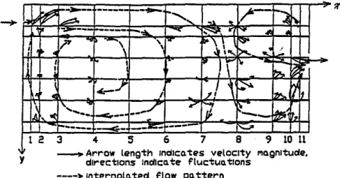
Effect of Diffuser Air Velocity At the hiJlb.c!st diffilser air velocity (Figure 3), thmo was a strongprimuy recireulation eddy in the uppor right comer and a
secon-clary recirculation eddy in the loweo- left comer.
The flow pattern in the medium diffuser air velocity test (Figure 4) was very similar to thst from the highest diffilser air velocity case, but the seconclary eddy at the lower left comer was not clearly observed in the
medium-velocity case. This may be explained by the reduced inertial effect due to the decrease in the diffilser air
velocity. The momentum in the reverse flow was not enough to generate the strong secoodary eddy in the lower left comer.
At the lowest diffilser velocity (Figure 5), the reverse flow below the diffilser jet occupied only a small uppor
portion of the flow field. This was again due to the small amount of momentum in the diffilser air jet, which resulted in much less entrained air. There appeared to be a large
weak recireulation flow in the lower portion of the flow field due to molecular viscosity, but the flow there was
essentially stagnant.
Effect of Tbennal Buoyancy For a lower intemal heat load, the diffilser air jet attacbM to the ceiling for a
longer distaoce before it separsted from the ceiling
(Fig-310
ures 6 through 8). Therefore, the effect of the thermsl buoyancy was to pull the diffilser air toward the floor. This
was expected bees'"" the incoming air bad a lower
temperature than the room air. ·The separation point of the diffilser air jet would depend on the balance between the CoaDda effect (or inertial effect) and the thermsl buoyancy effect. The CoaDda effect; which represents the inertial effect, is dependent on the air velocities within the jet. As the air velocities within the jet decay along the trajectory of the jet, the Coanda effect becomes smaller and smaller. The jet would start to separate from the ceiling surface
when the Coanda effect is equal to the thermsl buoyancy effect. The Afcbimedes number represents the ratio between the thermsl buoyancy and inertial effects and is therefore natumlly used to chsracterize the room airflow patterns.
It was also observed that flow in the nonisothermsl
cases bad stronger random behavior than in the isotherms!
cases. For the nonisothermsl cases, flow observed at the same location but at differeat times had more directional variations (Figure 7 vs. Figure 4).
Statistical Cherecteriatlca
Room airflow involves turbulence. The movement of fluid elements in a turbulent flow field bas a strong random feature. Statistical analysis of the air velocity signals within
the room is a fimd•IMI!tal step toward understsnding the flow behavior.
Features of tbe Velocity . As shown in Figures 9 and 10, the velocity sipals had strong random features. The air
velocities in the jet regiiiiiB contained more high-frequency fluctuations and
were
moro turbulent compared to those inthe occupied regions. A higher.diffilser air velocity resulted in more turbulent flow in the occupied regions. For the same diffilser air velocity, the thermsl buoyancy effect due to the heat generated from the floor also contributed to the generation of turbulence in the occupied region.
NLNセ@
-
1'-+
.-.
1"\ セ@\
\
ᄋセ@ セ@ 't\
'
!'o!\
\.
.... '\
'
"'
'
,,;_·...
セ@...
:_, .ol セ@/
"
.
セ@"""
イMNセ@ Gセ@'
.: .§., '.lo セ@--
Arrow length lndk:a. tes velocity Ma.gnttudedirections ll'lciiCD. te f\uctua. エセ」ョウ@
- - - - t Interpol.a. tid Flow pa. ttern
Flgun 3 Flow ptlltern of test Pl: Ud- 500fPm, ATr4 =
o•F.
-
セセイMセ@
-
---
セM--
1-·v-\
r-"::L.
..,
..!'- セ@I
Ir'\
ic-'
I -•
'
\
-1
セ@
..
\
\'·. <
1'7
I\,
.;;
...
\....
....
セ@·-,...
:.
Mセ@"'··
MMMセ@
....,
セMZZ\@
1'-....
-- A r r o w length lnalco. tes velocity roognltuae,
y c:llrect1ons 1na1c:o te f'luctuo t1ons
--<> Inter-polo tea overoU flow po. ttt'rn
Flgun 4 Flow ptlltern of test P2: Ud = 350./Pm. ATr4 -
o•F.
-
-::-12"t
---
----
---.A
(
.,
セL⦅@
....
'--,
.... X'
...._
A セ@r
-
t--... セ@ ......
,,..._
r-.,....,
...
\
セ@
!
(' ,__
,..,...
-
Mセ@
...
,
セM
...
-
...
..,
セ@
r\
....,_
...
,...,...,
-
---:1
.o.lIL
\r-
セMM
BMセ@
':_)
..,.
l' ... ,---
-
-
-
-Arrow length indiCQ. tes vetaoty Mgnttuae direc-tiOns IndiCate fluc:tua.tlons
Y ----• lnter"pota.ted F\ow po.ttern
Flgun S Flow pattern of test P3: Ud = 150./Pm, ATrd =
o•F.
1',
/'
. w( -...
=· ...
---
MセM_...,._
----
:..12 3 4 5 6 7 B 9 1011
y - Arrow length Indica. t u velocity l'lo.gnltude directions Indica. te fluctuo. tlons
---->-
Interpol a. ted Flow po. tternFlgure6 Flow pattern of test P4: Ud - 350./Pm, 4Tfd - 67.3"F.
'
yI!. I?'
セ@__
...,
-
'"
セ@,...
....
-
.... ᄋMセ@ ;:....ᄋセ@
J4
...,..
セ@-...
... !Y iセ@ セ@ .... セ@ 'l"'-I
(
•
セ@i
,
'V\.
•.
,,/
-
..
セ@
i
セ@-
_,.
I'
セ}@
""'
..-""
セᄋ@ 'l'j\
I...
7 I---
MMセ@....
1 2 3 4 5 6 7 B 9 10 11- A r r o w ャセョァエィ@ Indica. tes velocity l'lo.grutuae.
directions lndlco.te fluctuo.tlons ----)- Inter-polo. ted Flow po. tt.,.-n
Figure 7 Flow pattern of test PS: Ud = 350JPm, 4Tfd = 47.9•F.
y 1/!f !.A---
r----
f----- ---
--....
., tP •-
--
p---
セM...
L- セN@'&.
1"-1---::..
--,
...
セ@....
,
I I IF-.
LセL@1\"'
I'll
I \ \ r"" 'I,...
.
セI@ セ@ セ@ セGiA@--
---=:::
-
--.:.'S'
/""""
"'
iセ@ '--11...
--
../.--- - --
-1 2 3 4 5 6 7 B '9 10 11 Ar 1 a.tes v"'
It- r-ow length 1nd c eloc1ty o.gn ude,
directions lndlco.te Fluctuo.t1ons - - ) - Inter-polo. ted Flow po. ttern
Figure 8 Flow pattern of test P6: Ud = 350JPm, 4Trd = 29.6•F.
X
•oo;---,
350
セMᄋ@
__
LNLセ@...
Figure 9 Sample wlocity signals in test P1: Ud
=
500 fpm, <1Tfd=
o•F
(jl!l region: x/W=
0.125,y!H = 0.0521: occupied region: x/W
=
0.375, y!H = 0.6771).
Probability Density Function Probability density functions are shown for test P3 (Figure 11). The random fluctuation of air velocity at a fixed point followed tho notmal distribution in general for both isothermal and nonisothermal flows, although the latter were noted to follow the normal distribution more closely. Therefore, one
can use measured mean velocity and standard deviation to determine the velocity range at the measured point for a · Jiven canfidence level. This セ@ with the field
mea-SIIl'OIIIIIIIt results of Thorshauge (1982). Such information is useful for assessing the thermal comfort in ventilated buildings because one needs to know the percentage of time
when air velocities in the occupied regions satisfy the Jiven criterion.
The histograms of velocity fluctuations (Figure 11) are slightly right-skewed. This may be caused by the limitation of the hot-wire ane1110meter, which is unable to detect the
revene flow. ln other words, the negative velocities (i.e., air velocities in the negative direction) are sensed as positive values by the hot-wire memometer. As a result,
the histograms of velocity fluctuations are right-skewed
aince the negative velocities are folded to the right.
EDei')IY Spectral Dem.ity Function The energy
spectral density function, E(/), is defined as
+•
J
E(J) df,;, (u1)20
(1)
where (u')2 is the variance represeoting the total energy of the velocity fluctuation. E(/) 1ep1 e ents the distribution of
the kinetic energy of turbulence fluctuations over different frequency components. The higher-frequency components
correspond to smaller eddies and the lower to larger eddies.
·Velocities in the jet region contained higher levels of kinetic energy of turbulence compared to those in the
ASHRAE 1l"ansactions: Symposia
400;---, 350 300
!zso
,zoo
j
150 セ@ 100 50 - ( o f イセッョ@Figure 10 Somple wlocity signals in test PJ: Ud
=
150 fpm, <1Trd =o•F
(jet region: x/W=
0.125,y!H = 0.0521; occupied region: x/W
=
0.375, y!H
=
0.6771). 400,
..
"
g
セ@ 200g
,):,
..
·a. jet region:
x/W
=
0.125, y!H = 0.0521.ᄋセセセセセ]M
0•••
,
..
,
..
Figure 11 20 "'10 8D 80 100 120 Velocfty1 fpm Velocity, fpm b. occupied region: x/W = 0.375, y!H=
0.6771.Histograms of sample wlocity signals in test PJ: ud = 150/pm, <1Trd =
o•F.
occupied regions, especially for the Jow-diffusor..velocity cases (Figures 12 and 13). The distribution also exlellded to higher frequencies for the jet regions. The large velocity gradients in the jet regions were mainly responsible for generation of turbulence according to the turbulence theory
(Hinze 1975). High-velocity gradients also generated more
small eddies, which correspoodod to the high·frequeacy fluctuations.
It was also noted that thenDil buoyancy due to heat production from the floor
increas!=d
the turbulence ODefiY in tho occupied region, but had little effect on the turbulentkinetic enersy in tho jet region. Therefore, the contribution of thermal buoyancy to the turbuJeace production within the room is limited in the occupied region, which is close to the best sources (floor surfaces in this case).
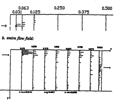
Mean Velocity
Spstial distributions of mean velocity are shown for test P6 (Figure 14), where all velocities are msde dimen·
sionless by dividing the local sir velocity by the diffuser sir velocity. The trajectory of the diffuser air jet can be tnlcod
by following the location at which the maximum velocity occurred in esch measurement column (xiW). A common
feature for all the tests was that the incoming sir jet bent toward the coiling after entering the room. It then traveled along the coiling for a certain distance before separating from the coiling again. This agrees with the flow patterns discuased earlier.
. ' In the region where the jet atl8cbed to the coiling, the
messured velocity profiles were similar to a "wall jet"
type of flow. Conventionsl wall jet theories (Schlichting
1979) may be tested with the present data to evaluate whether they adequately descnl>e lfUs region or whether modifications are necessary for acc:eptsbly accurate predic-tions.
The velocity profiles close to the floor (yiH
> .
75) did not show similarity with the wall jet type of flow but were more or Jess uniform. With a higher diffuser sir velocity (i.e., a higher Re,V than the case studied, a higher remaining momentum from the diffilset sir jet would be availsble to the reverse flow. Due to the surface effect, a wall jet type of flow would also be produced in the regioDa close to the floor, as repcrted by Tm and Ogilvie (1990). This is an important difference between high and low ventilation rate flows (i.e., between high and low Re,V.The average velocity in the occupied region increased with the Re4 as expected, but the dimcmsionless average velocity (UIU
.V
decreased (Table 2). Thia again indicates the dependence of the sir distn"bution on the Reynolds number. The decrease of the cfimen•ionless average velocity (UIU,V may be explained by the increased degreeof turbulent mixing when the Reynolds number increased. This is in agreement with the previous experimental resuits in a 1112th-scale model (Zhang et aJ. 1990). Other
resear-chers (e.g., Timmons 1984) showed that when the Rey-nolds number was larger than a threshold, the distribution
314 10000
l
::.
tOOO tOO ::.f
tO I li O.t!
0.01 o.oot o.ot o.t -(otroglon t tO Fr..-v. Hz too 1000Rgure 12 Energy spectra ofWJiocity in test PI: Ud
-500 Ji>m, 4Trd - o•F (jet イエセァゥッョZ@ xiW
-0.125, y!H
=
0.0521: occupied Ttlgion: xiW- 0.375, y!H = 0.6771). 10000
f
tOOO tOO セ@セ@ i- 10]
li O.tJ
0.01 o.oot O.Ot o.t_,
..
,
...
t !0 rr...-,, Hz--·eglon
1000Rgure 13 Enugy SJ¥ctra qf WJiocity In test P3: Ud .. 150 Ji>m, 4Tfd
=
o•F (jet rt1glon: x1W •0.125, y!H = 0.0521: occupied イエセァゥッョZ@ xiW = 0.375, y!H - 0.6771).
of mean sir velocity within a ventilated room became ind"iJeDdent of tho Reynolds number, and the lhreahold value increased with the room scale. However, 11101t
realistic room ventilstion flows have Reynolds numbers
well below the thresbold, as in tho present study. There-fore, the dependence of room airflows on the Reynolds
munber has to be considered in the study of realistic room ventilstion flows.
Increasing the thermal buoyancy effect decreased the distance the sir jet traveled along the coiling and also made
tho jet expand lister. When the jet fell, it produced a
region with relatively high air velocities in some part of tho
occupied region.
The average velocity in tho occupied region was higher in the nonisothermal case than in the isothermal case since the dif'fillier sir jet dropped directly to the occupied region (Table 3). However, for the three nonisothermal teat cases,
a. jot ,..glon: 0.063 0.250 0.500 0.031 0.125 セ@
It+
,
f
0.375f
f
b. DUi,..jlowfitld:•
yFflfiUW 14 Distrlbullon of mean velocity (UIUrJ)for tut
P6: Ud = 3SO.JPm, ATa - 29.6"F.
the average velocity in tho occupied region decreased with the increase of internal heat load and, hence, the
Archimedes number.· When the intemal heat load
increased, turbulent mixing dne to thermal buoyancy increased, resulting in a higher velocity decay in the diffuser eit jet and thus a lower - eit velocity in the
occupied mne.
Turbulence Intensity
The turbulence intensity is defiDed as the ratio between the atandard deviation (u') of velocity fluctustions and tho mean velocity (U). It represeota the degree of turbulence at a local point.
The distribution patterns of the turbulence intensity within the test room were not as apparent as in the mean velocity distribution (Figure lS). In general, relatively high values were distributed in the intennittent region at the edge of the diffuser eit jet and at the central region of the recirculation eddy.
TABLE%
Dependance of Averaga Velocity
In tha Occupied Region • on the Reynolds Number
ur
fpm Red U,fpm U/Ud Toet150 2458 16.2 0.108 P3
350 5488 27.0 0.077 P2
500 8192 35.7 0.070 P1
•The occupJed region it deflned •• tt. .-:a from the floor to • 8-foot-high lewl and 1 foot from eRh licle wall, whklh oomttponclt
to 0.25 < v/H < 1.0 and 0.6 < X/W < 0.14. イ・。ーセN@
ASH RAE Transactions: Symposia
a. jot ,..gion:
0.063 0.2'50 0.500
0.031 0.125 0.37'5
セ@
I
Jl
J
セ@
セ@
t
Ib. tlllim flow fitld:
-Flpre 15 Distribution ofturbulenc. intensity (100 u'IU)
for tut P6: U4 - 350 .JPm, ATfd • 29.6"F.
The average turbulence intensity in the occupied region increased with the increase of diffuser air velocity, as
expected (Table 4). It also increased with the internal heat load because the thermal buoyancy caused the diffuser jet
to drop into the occupied region and also contributed to the production of turbulence within the occupied region. Turbulent Kinetic Energy
The kinetic energy of turbulence (k) is defined as 0.5
u•2. It is a more appropriate term to represent the impor-tance of the turbulence effect on the room air motion than turbulence intensity. The kinetic energy of turbulence in the diffuser jet region was substantially llrger than in the occupied region (Figure 16), especially in the isothermal
teats. Since the magnitude of turbulent kinetic energy in a local region depends on the turbulence generated within the region and that transported from upstresm, one may infer
TABLE3
Dependance of Average Velocity
In the Occupied Region • on the Archlmedu Number
4Trr •F Atfd U,fpm U/Ud
T-o.o 0.0 27.0 0.077 P2
29.6 0.0085 35.4 0.101 P8
47.9 0.0135 33.5 0.098 P5
87.3 0.0188 28.0 0.084 P4
•The occupied regkm It defined •• the tpace from the floor ta a
6-foot•high tevel and 1 foot from elleh aide w•H, whJoh correspond• to 0.26 < y/H < 1.0 and 0.5 < x/W < 0.94, twspectively.
a. jet l'l!glon: 0.063 0.250 0.500 0.031 0.125
...
-
-
.
MセヲM
,
-
..
•
f
セ@セ@
セ@
;-"'
_,
f-·-
..
...
-.
·-yFigure 16 Distribution oftUI'bulent kiMtic eMrgy (k/O.S
Ui} for test 1'6: Ud • 3SO fpm, 4Tm •
29.6°F.
tbat the turbulence within the room wu mainly generated in the diffuser jet region due to the strona intenction between the incoming air and the room air and between the jet and the ceiling surfaco. The generated turbulence wu
then transported to the other parts of the room. In the · transport process, the velocity fluctuations were also
damped by viscous effects, セャゥョァ@ in lower IUrbuieat
kinetic energy in the occupied region. This phenomenon
asrees
with the turbulence theoty (Hin.ze 1975), since largemean velocity gnulients were present in the jet region but not in the OCCPpied region.
'Ihenondimensionalizedturbulentkineticenergyofthe occupied region wu larger in the.cue of a higher diffuser
u.,.
fpm 150 350 500 350 350 350 TABLE4Average TUibulence Intensity
In the Occupied Region •
"""
r,.
Allot 11'/U, •F...
2458 0 0 8.5 5438 0 0 23.8 8182 0 0 27.8 5438 28.8 0.0085 28.1 5438 47.8 0.0135 28.8 5439 87.3 0.0188 33.8 T-P3 P2 P1 P8 PS P4 · , . . oooupJM region It deflnecf nthe..-fn:Nn the floor to • 8-foot.hlth .. ,.. and 1 foot from •Nh N:te Will. which oo,.tPGndt ... 0.25 < y/H < 1.0 .... 0.6 < - < 0.114 ... ly.316
velocity (Table S). If the cliffiaser air velocity セ@
fllrther, a sufficiently high-velocity snufient may be present
between the &Oiid llllrfacea of the opposite wall and the floor and the adjacent flow, resulting in signifiCIIIIt
tur-bulence production and thereby increasing the turbulent kinetic energy in the OCCPpied region signifiCIIIItly. How-ever, IIIOBI realistic ventilation flows have low velocities
( <
SO fjlm) over the floor surface 50 tbat such adclitionslturbulence production ia negligible compared to the turbulence production in the jet region •
The average turbulent kinetic energy of the occupied region in noni&Othermal flows wu approximately US 96
larger than in the isothermal flows (Table S). This wu ·
again pattly due to the contribution of thermal buoyancy to
the turbulence production, especially within the OCCPpied region itself, and pattly due to the drop of the cliftUNr jet into the occupied region •
Me111 Temperstul'll
· The clistribution of moan temperature for the noniso-thermal tests conducted wu mainly determined by the
moan velocity clistn'bution (Figure 17). In other wotds, the
temperature wu lower upa1team of the flow. As the air
lnlveled, it wu heated by the adjacent WIII'IDBr air through turbulent mixing and molecular cliffusion.
·In the OCCPpied region, the room air tempentures were much more uniform than the moan velocity セG「オエゥッョN@
This is mainly becs"'O the temperature field had cliffetent
boundary conclitions from the velocity field. Temperatures on the surfaces of the walls, ceiling, and floor were higher
than (on the floor surface) or equal to (on other surfaces, assuming adiabatic conclitions) the temperature of the air
altached to the llllrfacea, while the air velocities on these surfaces were 11110 due to the air viscosity. Adclitionally, the molecular host cliffusion wu faster than the molecular momentum cliffusion since the Prandtl number of the air ia
TABLES
Average Kinetic Energy of Turbulence
•
In the Occupied Region
u.,.
R•otr,.
Ar,. k/10.5 UJ 2 Tutfpm •F 150 2458 0 0 0.00009 P3 360 5438 0 0 0.00042 P2 500 8192 0 0 0.00044 PI 350 5438 28.8 0.0085 0.00082 P8 350 5439 47.9 0.0135 0.00098 PS 350 5438 87.3 0.0188 0.00092 P4
•The occupied rogkJn Ia defined •• the apttee from the floor to a 6-foot·hiah lewl and 1 foat from e.ch tide wall. which corretpondt to 0.25 < YIH < 1.0 and 0.68 < x/W < 0.94. reapectivelv .
... jel ,..gion: 0.063 0.250 0.500 0.031 0.125 0.375
セA@
tl
l
セ@
[
セ@
b. tllll,.. j/Dw Jl•ld:...
..
Figure 17 Distriblllion of temperature [(r - Td)lt.TrJ
for test P6: Ud • 3SO.fpm, t.T61 • 29.6"F.
about 0. 7. The Prandtl number repteaenls the ratio between the momentum and thermal diffusion rates due to molecular motion (Kays and Crawford 1980).
SUMMARY AND CONCLUSIONS
. 1:- Turbulence of room venlilltiOD flows is mainly gener· ated by the diffilser air jet. The turbulent kinetic auqy in the occupied regioas is significantly smaller and is distributed in a lower frequency nmge than in
the diffilser jet repon.
2. Normal distribution can be Uled to approximate the
velocity fluctuations in the room venlilltion flow. 3. Air distribution in realistic isochermaJ venlilltion flows
is dependent on the Reynolds JIWIIber. 1'ncreasing the
Reynolds number
(Re,V
docreues the dimensionless avemge velocity (UIU,V IIIIi incresses the turbulent kinetic auqy and turbulence intensity in the occupied repon.4. . The internsl heat load may have significant effects 011
the room air distribution, CltJsjng the diffilser air jet to fall more quickly after llllering the room. 'Ibis CSUBeS
a higher spltisl avemge of mean velocity in the
occupied repon for the JIOIIisothermal cases compared to the isothermal case Ullder the same diffilser air
. velocity. The thermal buoyaucy also contributes to the
turbulence production within the room and thereby
increases the turbulent kinetic energy and turbulence intensity in the occupied regiOD.
The detailed measutelllellts of distributions of air
velocity, turbulent kinetic energy, and turbulence intensity
ue also useful for evaluating セ」ウャ@ simulation models.
ASH RAE Transactions: Symposia
ACKNOWLEDGMENT
'Ibis study wu 8p01180red by the U.S. Nlticmal ScieDce Folllldation and the University ofDJinois Campus a-reb Board. Their fillancial support is highly appreciated. The
authors ue also snteful for the help of Iolien de Vos,
Steve Ford, and Bo Zhang in conducting the experiments. NOMENCLATURE
ach
-
air changes per hourArp
-
Archimedes JIWIIber, defined u/1gwJ,7j
-T,VIUi
E(/)
-
spectral density function of velocityfluctua-lions,
q,m2
(mls)'-I
-
frequency.Hz
g
-
gravitational acceleration rate, tpml (mls)2H
-
room height, ft (m)k
-
turbulent kinetic energy, q,ml (m/s)2L
..
length of the room (in Z direction), ft (m)ld
-
leugth of the diffilser slot (in Z direction), ftQ
-(m)
venlilltion rate,
ft'
/min (m3/s)Re
-
Reynolds number, defined u UdwJr7j
-
ma·dmnm temperature in room (e.g., on the heated surface), •p (0C)Td
-
diffilser air temperature, •p (0C)T,
-
oir temperatwe at the exhaust, •p (0C)t.T<d
-
T. -
Td, •p (•C)t.lj,
-
7j -
T.,. •p (•C),.
-
standard deviltion of velocity,fPm
(m/s)utl = reference velocity, diffilser velocity at the measurement plane (z • O),fPm (m/s)
w
-
width of the test room (in X direction), ft (m)w.,
-
width of the diffilser slot (in Y direction), ft (m)w.
..
slot width of the exhaust, ft (m) z,y,z-
Eulerian· Cartesian coordinates, ft (m)Ytl
=
distance from the ceiling to the diffilser upper・、ァセL@ ft (m)
Y,
-
distance from the ceiling to the upper edge ofa
-the exhaust, ft (m)
thermal diffUsion coefficient, ttl/min (ml/s)
11
=
thermal expansion coefficieut, 1/R (1/K)"
-
kinematic viscosity, ttl/min (m2/s)p
-
density of diffilser oir, lbmlftl (kg/ml) REFERENCES(
ASHRAB.1989.1989ASHRAE handbook-FIUIIiDtMntals.
Atlanta: American Society of Heating, Refrigemting, and Air-Conditioning Bnsineers, Inc.
Barber, B.M., S. Sokgansanj, W.P. Lampman, and I.R. Ogilvie. 1982. Stability of oir flow patterns in veu-tilated spaces. ASAE Paper No. 824551.
Baturin, V.
v.
19n. FruuiatMntals ofindustrlal-lkuion,. . 3d eel. Oxford: Perpmoa P:n:a.
Boon, C.R. 1978. Airflow pUtenl8 1Dd temperature
distribution In ID experimcatai pigery. J. llgric. Engng. Ru. 23(2): 129-139.
Carpenter, G.A., L.J. Moulsley, IDd J.M. Randsll. 1972. Ventilstion lnvestisstions
usm.
a aeclion of a livestock buildlns and airflow visuaUution by bubbles. J.llgric. Engng. Ru. 17(4): 323-331.ChristiiDSOn, L.L. 1989. Building systems: Room alr and alr colllomilltllll distributio& AtiiDta: American Society of Heatins, Refriseratins. IDd
Air-Condition-Ing Engineers, Inc. ·
Filmer, K.F. 1981. Airflow experiments In filii-scale test
rooms. ASHRAE Transactions 17(2): 1143-1153. Hart, G.H., IDd D. Int-Hout. 1980. The performsnce of a
continuous linear air diffuser in the perimeter zone of ID office environment. ASHRAE Transactions 86(2): 107-124.
Hinze, 1.0. 1975. 1Urbuknce. New Ymt: McGraw-Hill, Inc.
Jln, セNL@ IDd J.R. Ogilvie. 1990. N - floor air speeds from center slot air inlets In swine barns. ASAE Paper No. 904004. St. Joseph, MI: American Society of Agricultural Engineers.
Kays, W.M., IDd M.E. Crawford. 1980. Convective hear
and mass transfer. New Yodc McGraw-Hill, Inc. Melikov, A.K., H. Hanuwa, IDd P.O. F1Dger. 1988.
Airflow characteristics In the occupied zone of bested ·.spaces without mechanical ·ventilation. ASHRAE
Transactions 94(1): 52-70.
Miller, P .L., IDd R.G. Nevins. 1972. An analysis of performsnce of air distributioa systems. ASHRAE
Transactions 71(2):.191.
Mwakami, S., IDd S. J{ato. 1991. Numerical prediction of
horimntal nonisothermal 3-D jet In room based on the
1c-e model. ASHRAE TransactioM 97(1).
Nevins, R.G., IDd P.L. Miller. 1972. Analysis, evaluation and comparison of room air distribution
perfor-mance-A mmmary. ASHRAE Transactions 78(2): 235-242.
Ogilvie, J.R., IDd E.M. Barber. 1988. Jet momentum
IIWDber: An index of air velocity at floor level. In
BuiWng systems: Room air and air colllambutnt distribution, ed. L.L. Chrislimson, pp. 211-214. Atlanta: American Society of Heatins, Refrigeratins, DISCUSSION
A.J.
Baker, Professor, University ofTennessee,
Knox-ville: Your hot wire can measure UINDt 1Dd"il
fluctuations. You show TKE levels, which require knowing"iliJ
and7il
and f i . For directional flows, such as boundary layers, these latter two data are significantly smsller than"ilil.
Hence, your reported TKE level is too large. Comments?318
and Air..condltioalng Engineers, Inc •
Randall, J.M. 1975. The prediction of airflow patterns In
livestock building. J. llgric. Engng. Ru. 20(2): 199· 215.
Randall, J.M., and V.A. B•ttsms. 1979. Stability criteria for airflow pUtenl8 In livestock buildings. J. llgric. Engng. Ru. 24(3): 361-374.
Sandbe!g, M. 1989. Velocity characteristics In
mechan-ical1y ventilated office rooms. In Room Vent '87, Proc. In llllmrarlonai Col!{ermce of Air Distribution
in vエセャャャゥォオ・、@ Spactls, Session 2A, Stockholm, Sweden,
10-12June.
Schlichting, H. 1919.Bolmdaty-layer tht!ory. New Yodc McGraw-Hill, Inc.
Straub, H.E., and M.M. Chen. 1957. Distribution of air
within a room for y--round air-conditioning-Part H.
University of lllinois Engineering Experiment Station Bulletin, No. 442. Urbana: University of Dlinois. Thorshauge, H. 1982. Air velocity fluctuations In the
· occupied zone of ventilated spaces. ASHRAE
Transac-tions 88(2).
Timmons, M.B. 1984. Use of physical models to predict the fluid motion in slot-ventilated livestock strnctures.
A&4E Transactions 27(2): 502-507.
Whittle, G.E., IDd E..M. Clancy. 1991. Evaluation of cues B,D,E-Pre.ltation of results from
-meats and simulations.IBA Annex 20 Research Report
No. 1.22.
Wu, G.J., L.L. Christianson, J.S.
Zhan&,
and G.L.Riskowski. 1990. Alljustsble room ventilstion
simu-lator for room air and air COIIt•min•nt distribution . modelins. In Indoor Air '90, Proc. .5th lntmtational Confermce on Indoor Air Quality and cャャュ。エエセTZ@
237-242.
Zhang, J.S. 1991. A ftmd•IIWital study of two dimensional room veatilstion · flows under isothermal and non-isothermal conditions.
Ph.D.
thesis, University of Dlinois at Urbana-O•mpaign.Zhang, J.S., L.L. Christianson, IDd G.L. Riskowsld. 1990. Regional airflow characteristics In a
mechanical-ly ventilated room under nonisothermal conditions.
ASilRAE Transactions 96(2).
Zhang, J.S., G.J. Wu, IDd L.L. Christianson. 1992. Detsiled lllll88ll1'eDie of room air distribution for evalusting numerical simulation models. ASHRAE Transactions 98(1).
Jianshun Zhang: Thank you for your question, Jerry. It is important to note that the single wire probe used in this
study only measutes the total velocity of the two-dimen-sional flow in the x-y plan. It does not measure each velocity component. The turbulent kinetic energy (TKE) presented In this paper was calculated based on the fluctua-tion of the measured total velocity. The same definition should be used when the data are used for comparison with numerical simulation results or other measured results.