CHARACTERIZATION OF A MAGNETICALLY
LEVITATED TESTBED FOR ELECTROSPRAY
PROPULSION SYSTEMS
A
By
Fernando Mier Hicks
B.S, Mechatronics Engineering Monterrey Institute of Technology (2011)
MASSACHUsETTS E OF TECHNOLOGY
JUN 16 2014
UBRARIES
Submitted partialto the Department of Aeronautics and Astronautics in fulfilment of the requirements for the degree of
MASTER OF SCIENCE IN AERONAUTICS AND ASTRONAUTICS at the
MASSACHUSETTS INSTITUTE OF TECHNOLOGY
June 2014
Copyright, Massachusetts Institute of Technology 2014. All rights reserved
Signature redacted
A uthor...
Depart
Accepted by...
...
men\ of Aeronautics and Astronautics May 2014
Signature redactedw
. . . . .. .. .. .. .. . .... .. .. .. . . .. .. . Paulo C. Lozano Associate Professor of Aeronautics and Astronautics
Thesis Supervisor
Signature redacted
....
... ...
....
...
...
\~ Paulo C. LozanoAssociate Professor of Aeronautics and Astronautics Chair, Graduate Program Committee y ... I I
CHARACTERIZATION OF A MAGNETICALLY LEVITATED TESTBED FOR ELECTROSPRAY PROPULSION SYSTEMS
By
Fernando Mier Hicks
Submitted to the Department of Aeronautics and Astronautics in partial fulfilnent of the requirements for the degree of Master of Science in Aeronautics
and Astronautics at the Massachusetts Institute Technology June 2014
ABSTRACT
Small satellites are changing the space scene dramatically. By drastically reducing costs while still having impressive technological
capabilities, their popularity among the space community is increasing at a very fast rate. Propulsion systems for these class of spacecraft are very limited. One promising technology is the ion Electrospray Propulsion System (iEPS) developed at the Space Propulsion Laboratory at MIT. Electrosprays accelerate ions present in the interface between an ionic liquid and vacuum using strong electric fields. Current thrust estimates for the
iEPS modules land in the vicinity of tens of ptNewtons. Measuring the small thrust produced by the devices is challenging to say the least. This thesis presents the design and development of a Magnetically Levitated Thrust Balance (MLTB) for thrust estimation of the iEPS devices.
The MLTB levitates an engineering model of a small satellite using magnetic fields inside a vacuum chamber. The zero friction environment is exploited to measure the minute thrust levels produced by the electrospray thrusters. Additional sensors and actuators that provide added functionality to the instrument are also explained. A fully stand-alone Power Processing Unit (PPU) capable of generating and delivering the high voltage signals needed to drive the thrusters is explained in detail. Test results of charging behavior and lifetime characterization of the emitted current are presented as a preliminary exploration of these processes.
Thesis Supervisor: Paulo C. Lozano
ACKNOWLEDGEMENTS
Space is the ultimate frontier for humankind. What better occupation than to try to tackle this boundary. My experience at the Space Propulsion Lab has been one of pure joy and excitement. Mainly attributed to the fantastic leadership and mentoring of my advisor, Dr. Paulo Lozano. I thank him for giving me the opportunity to work along with and learn from such a bright mind. He helped me discover my true potential, helping me become a better scientist in every chance he had.
I want to thank all the SPL members for countless hours of company
and friendship inside and outside of the laboratory. They helped make the
SPL a very happy and fun place to work.
My family is the primary reason I can even write these words. By
always challenging me in what I could become, they forged my way to MIT. The engineering passions of my dad and my grandfather gave me the motivation of pursuing a technical degree. I will always be grateful to them for guiding me and showing me what technology can do for us. I specially thank my father, Angel, for giving me the opportunity to use his home-made lab as my classroom when I was young, as well as guiding me and helping with my projects. I am proud to be an engineer just like them.
My mom, Mariela, was the driving force that guided my course along
the years. With her continuous support and words of encouragement, I can navigate through life. I owe so much to her. The rest of my family deserves just as much recognition and gratitude, my brothers and sister, my
grandmother, uncles and aunts, all of them giving unconditional support and offering insightful advice.
Lastly I want thank Annie, my girlfriend, an addition to my life that has brought enormous amounts of joy and support. I wouldn't have made it without her.
I want to thank all of you for all the help and support I have received
TABLE OF CONTENTS
1
Introduction...
11
1.1 Satellite trends ... 11
1.2 Propulsion basics ... 13
1.3 Current space propulsion technologies... 17
1.4 Electrospray propulsion... 19
2
Electrospray characterization ...
21
2.1 T hru st ... . . 23
2.1.1 Torsional balance... 23
2.2 Specific impulse ... 24
2.2.1 Time of flight mass spectrometry ... 24
2.3 Spacecraft charging effects ... 26
2.3.1 Scenarios ... 26
2.3.2 Self-regulating mechanisms ... 27
3 M agnetically levitated testbed...
31
3.1 Concept and innovations... 31
3.1.1 D esign ... 33
3.1.2 Thrust measurement... 34
3.2 Sensors and actuators... 37
3.2.1 Main electromagnet ... 38
3.2.2 Vertical position sensor... 40
3.2.3 Angular encoder... 42
3.2.4 Charge sensor... 44
3.2.5 Electromagnetic damper ... 46
4
Controller and levitation results ...
51
4.1 PID controller... 51
4.2 Characterization of oscillations ... 53
5
Power Processing Unit (PPU) ...
59
5.1 E lectronics ... 60
5.1.1 Outgassing and high voltage... 61
5.1.2 High voltage generation... 63
5.1.3 High voltage switching... 64
5.1.4 Housekeeping circuitry... 65
5.2 Softw are... 67
5.2.1 Communications ... 67
5.2.2 Support software... 67
6 Tests...
69
6.1 Thruster charging results ... 69
6.1.1 Experimental setup ... 69
6.2 Lifetime characterization... 73
6.2.1 Experimental setup ... 73
7 Conclusions and reconnendations...
77
LIST OF FIGURES
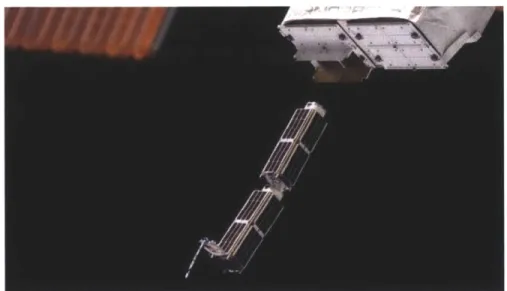
Figure 1.1 Two 30-cm long satellites, Planet Labs Doves, being launched
b y th e IS S ... . . 12
Figure 1.2 Change in velocity with respect of propellant mass fraction 16 Figure 1.3 Basics of electrospray ion evaporation... 19
Figure 1.4 Simplified diagram of an iEPS thruster... 20
Figure 1.5 iEPS device next to a US penny... 21
Figure 2.1 Typical voltage vs current curve for an iEPS device ... 22
Figure 2.2 Simplified schematic of a torsional balance [6]... 24
Figure 2.3 Basic schematic of a TOF system... 25
Figure 2.4 Firing schematic for an iEPS pair ... 27
Figure 2.5 Sample IV curve including intercepted current ... 28
Figure 2.6 Basic firing diagram of iEPS devices ... 29
Figure 3.1 Exploited degree of freedom shown in blue ... 32
Figure 3.2 CAD render of the magnetically levitated thrust balance.... 33
Figure 3.3 Sensitivity of thrust measurement with lever arm length .... 35
Figure 3.4 Sensitivity of thrust measurement with moment of inertia.. 36
Figure 3.5 FTS-100, a micro force probe sensor ... 37
Figure 3.6 Steady bias lifting force magnitude of permanent magnet, sid e v iew ... . . 39
Figure 3.7 Attracting force magnitude with one Ampere of current ... 39
Figure 3.8 Repulsion force magnitude at one Ampere of current ... 40
Figure 3.9 Optical shadow sensor concept ... 41
Figure 3.10 Optical shadow sensor electrical diagram... 41
Figure 3.11 Transfer function of optical shadow sensor... 42
Figure 3.12 Computer vision algorithm overlay... 43
Figure 3.13 Charge sensor concept ... 45
Figure 3.14 Wiring diagram for charge sensor ... 46
Figure 3.15 Electromagnetic damper concept ... 48
Figure 3.16 Electromagnetic damper performance... 49
Figure 4.1 PID controller block diagram... 51
Figure 4.2 Position over time of the levitated object... 53
Figure 4.3 Oscillations amplitude over time ... 54
Figure 4.4 36 hours oscillation profile ... 54
Figure 4.5 Representation of the imperfection in the magnetic fields ... 56
Figure 5.1 Block diagram of PPU ... 59
Figure 5.3 Paschen curve... 62
Figure 5.4 H-Bridge configuration... 64
Figure 5.5 Isolated current measurement schematic ... 66
Figure 6.1 Charging experimental setup ... 70
Figure 6.2 IV curves of the two thrusters used in the charging exp erim ents ... 71
Figure 6.3 Emitted currents and extractor potential over the course of the experim ent... 72
Figure 6.4 Current behavior over time... 74
1
Introduction
The space industry is evolving very rapidly. In the last couple of years, commercial companies have taken over tasks one thought to only be doable
by large governmental corporations such as NASA. The International Space
Station (ISS) is currently being serviced by commercial companies on a regular basis. These significant changes complement the past, and outdated, space philosophy to change. The idea that the only way to get to space is
by building large, complex and costly spacecraft is no longer the only idea.
New opportunities emerge for audacious missions that are willing to change the paradigms of traditional satellite engineering.
Space has been always a risky endeavor. Sending a satellite into Earth's orbit requires extensive knowledge and engineering in all systems involved, from the main rocket's actively cooled nozzle to the screws and nuts in the payload structure. Space systems are inherently high-cost due to their advanced technology and their need of reliability; they must be proven to work under all circumstances. A failed attempt in space is both
embarrassing and extremely unprofitable. Since the system is costly to begin with, increasing its reliability and ability to tolerate more risk escalates the cost even more. These characteristics also increase the complexity of the project because extra systems that add reliability and redundancy have to be incorporated into the design. As complexity grows, the time to design and execute the mission also grows. Following this philosophy we end up with what, until recent years, has been the only way to get into space; very few, complex, large and extremely high cost
missions. The previously mentioned approach to space is commonly referred as the space spiral. [1]
1.1 Satellite trends
Small satellites were conceived to invert the space spiral and make space more accessible. California Polytechnic State University [2] started the CubeSat standard, a small satellite architecture that tips the space spiral upside down. Standardization and reduced size are the two key
characteristics of the CubeSat philosophy. The whole premise relies on less costly, less risk averse, and more frequent missions. CubeSats are small
spacecraft based on single units. A single unit is comprised of a cube measuring 10 centimeters per side. Several of these units can be stacked to provide larger volumes for different spacecraft designs. Being much smaller than the normal satellite, CubeSats weight orders of magnitude less than a traditional spacecraft. With current launch costs averaging around $10,000 per kilogram launched [1], CubeSats reduce cost by reducing volume and mass. These small satellites usually ride along bigger satellites and get individually deployed at some point in the orbit. Other options for deployment include launching them from the International Space Station.
Figure 1.1 Two 30-cm long satellites, Planet Labs Doves, being launched
by the ISS
The CubeSat philosophy relies on accepting a larger risk for the mission.
A higher risk tolerance translates into lower reliability parts and less
redundancy, this reduces cost tremendously. To reduce costs even further CubeSats often rely on Commercial Off-The-Shelf components (COTS) in their construction. Standard electronic components that are used every day in smartphones and other miniaturized devices have characteristics that make them very attractive to space designs. Low power consumption and high computing power, all with a small footprint make these COTS very desirable in small satellite designs. Even though COTS are not designed to be radiation tolerant, CubeSats are usually in low enough orbits to avoid significant radiation doses that could damage their components. Satellites that benefit from processors that follow Moore's law (computing power increases two fold every 2 years) are able to engage more demanding
missions while at the same time consume moderate amounts of power and occupy a fraction of the available
1 liter satellite volume.
Besides computing power, COTS components are also desirable in communications circuits. Radio transceivers and amplifiers capable of handling several watts of power open up high data rate communications channels to these small satellites. To generate enough power in such a small area, high efficiency cells are employed in almost all CubeSats. With
efficiencies ranging in the upper 20% range, 1-unit CubeSats are able to generate around 5 watts of power. To control the attitude of the satellite, miniature reaction wheels and magnetorquers exist in several configurations for CubeSats.
The full extent of CubeSats has only begun to be explored. Current missions range from atmosphere analysis to multi satellite constellations for frequent Earth imaging. The future for small satellites is promising.
1.2 Propulsion basics
COTS devices including communication modules, battery systems, solar
panels and micro-computers have all been proven in space on different CubeSat missions. Nevertheless, capabilities of these spacecraft remain constrained by the orbit in which the launcher injects them; these satellites usually ride as secondary payloads. Once deposited in their predetermined orbit, they drift and are victim of orbital perturbations that usually end in atmospheric re-entry. Propulsion would open up the range of missions CubeSats could execute. Propulsion is one of the most challenging subsystems for a small satellite, the miniaturization of propulsion devices that are usually used on larger spacecraft is limited not only by the lack of technologies but in some cases by the physics governing the specific
thruster.
In the vacuum of space, Newtonian physics primarily limits the propulsion devices used to those that work by expelling some mass,
commonly referred as propellant, at some velocity. Newton's third law, "For
accelerating propellant, the spacecraft will suffer an opposite but equal acceleration. This force is called thrust. Since the spacecraft has to carry the propellant mass it will be ejecting, it is easy to see the reduction in acceleration this causes due to the increase of total mass. After ejecting all the propellant available the spacecraft will be traveling faster than before, this change in velocity is usually referred as delta-v. Delta-v is a common way to gauge orbital maneuvers, the more delta-v required to perform an orbital change the more propellant the spacecraft will have to consume to achieve the change in velocity. Common orbital maneuvers include changing the orbital plane, increasing the semi major axis, or circularizing the orbit, all of these can be classified by how much delta-v is needed to perform them. It is important to notice that some maneuvers do not change the velocity of the spacecraft but still require the use of propellant.
Maneuvers such as attitude control and atmospheric drag counteraction are examples of maneuvers that do not modify the spacecraft velocity but they do consume propellant, therefore a delta-v cost can be associated to them.
Other types of propulsion devices that do not work on the ejection of mass principle, such as solar sails and tethers, are usually bulky and not practical for use in small satellites.
The basic equation governing propulsion in space is the well-known rocket equation.
mspacecraft mfinal -AV
mpropellant + mspacecraft minitial
(11
This equation is derived from a closed system with no external forces acting on it while using momentum conservation as a method to relate the exhaust properties with thrust. The rocket equation, ( 1.1 ), relates the spacecraft mass, mspacecraft, and propellant mass, mp,,pl,,lt, with the change in
velocity, A V, that can be achieved after the thrusting device expels all the propellant mass at velocity c. Further analysis of the closed system provides the following relationship.
F = mic (1.2)
The previous equation relates the thrust, F, generated by the propulsion device and states that is directly proportional to the velocity at which the
propellant mass is ejected, c, times the mass flow rate of the propellant, in. It is useful to redefine the exhaust velocity of the engine, c, with the total impulse given to the spacecraft. The specific impulse, Isp (1.3), is defined as the total impulse imparted to the spacecraft divided by the weight of the propellant used to produce this impulse, if the variables are constant. The total impulse imparted is equal to the mass flow rate, in, multiplied by the exhaust velocity, c, and the burn time, t. The weight of the propellant is
simply its mass, m, times the gravity constant, g. The specific impulse equation simplifies to the exhaust velocity divided the gravitational acceleration at Earth's surface, 9.81 m/s2. The units of specific impulse are seconds.
Isp rh c t c (1.3)
mg g
The rocket equation shows the exponential relationship between the propellant that is needed to be ejected from the spacecraft to provide thrust and the amount of change in velocity achieved by this action. Analyzing the equations stated earlier we can infer the general trades that have to be made in terms of propellant mass that has to be carried, the final change in velocity that can be achieved, and the specific impulse of the propulsion device.
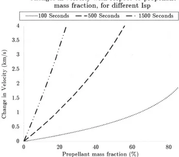
The following graphic depicts the amount of propellant mass fraction needed to accelerate a spacecraft in order to achieve a certain delta-v. The propellant mass fraction is simply the propellant mass plus the spacecraft mass divided by the spacecraft mass excluding propellant. An 80% mass fraction indicates 80% of the total mass of the spacecraft is propellant. It is assumed that the spacecraft mass includes the propulsion system mass but excludes the propellant mass. Several specific impulses are graphed to give a comparison of different thruster technologies. A low propellant mass fraction and high delta-v is desirable, but not always possible. It is clear to
see how a high Isp allows the spacecraft to carry less propellant for any given change in velocity, but not without consequence.
Changes in velocity with respect to propellant mass fraction, for different Isp
---..-.- 100 Seconds -- 500 Seconds - 1500 Seconds
4.I /' 3.5 _. 3 / 2.5 / . 0/ U / 1.5 / / 0.5 *, .. . .... 0 20 40 60 80
Propellant mass fraction (%)
Figure 1.2 Change in velocity with respect of propellant mass fraction
Currently, there are mainly two power sources that allow a spacecraft to eject mass in space to produce thrust, chemical or electrical energy.
Chemical propulsion is based on the use of energetic chemical reactions to accelerate the propellant through a nozzle. Electric propulsion usually employs electric fields to accelerate ions and provide thrust. Both methods have very different applications and characteristics.
In order to analyze the differences between the two classes of propulsion technologies it is useful to analyze the power and energy input to the device. Energy must be transformed from its initial state, either electric or chemical, to kinetic energy in the exhaust particles and of the spacecraft. This means that a high exhaust velocity requires a larger amount of energy.
The energy imparted to the exhaust particles cannot be provided instantaneously, meaning we can assume that the acceleration of the exhaust particles takes place at a fixed rate, therefore at a specific power level. An efficiency factor, rj, describes the efficiency of the engine to impart
energy to the exhaust particles. If the efficiency factor is also taken into account, we arrive at the following equation relating power, P, spacecraft mass, M, and acceleration, a, of the spacecraft.
Energy Mac
P = =
Time 2 r7 (1.4)
For a fixed power, a higher exhaust velocity, c, entails a lower
acceleration of the spacecraft and vice versa. This is the common relation in space propulsion, higher specific impulse generally entails lower thrust due to the limit on how much energy the rocket can carry or produce at a given time.
Chemical thrusters generally provide more thrust at lower specific impulses than their electric counterparts. They accelerate a large mass of propellant to relatively low velocities. The majority of electric thrusters oii the other hand accelerate light ions to very high velocities, providing higher specific impulses but lower thrust levels. Small satellites can't afford to carry large amounts of propellant so they are generally in need of high specific impulse thrusters that produce thrust while consuming very small amounts of propellant. The lower thrust level from the high specific impulse devices is compensated by activating the thruster for a longer period of time. It is not unusual to fire electric thrusters for thousands of hours. The mass and volume of the electronics needed to drive electric thrusters are also important factors of the overall system. Since the thruster power is proportional to specific impulse, there is a practical limit on how high the specific impulse can be. Usually there is an optimal value of specific impulse depending on the goals of each mission. Popular electric thruster
technologies for large satellites rely on bulky tanks and heavy thrusters. Scaling these devices down to the CubeSat volume is challenging to say the least.
1.3 Current space propulsion technologies
Satellites employ propulsion devices to make orbital manoeuvers that inserts them into an appropriate orbit. These manoeuvers take a certain
amount of energy to perform. The acceleration and the final velocity
achieved is dependent on the mass of the spacecraft, mass of propellant and the energy used to accelerate propellant. In space propulsion and
Astrodynamics it is more common to gauge these maneuvers not in terms of energy, but in the finite amount of change in velocity, delta-v, that the satellite achieves after activating the thruster. Delta-v also applies to attitude control maneuvers, even though the satellite does not change its position in the orbit, making it rotate uses energy that can the translated into some delta-v value. In general the delta-v achieved can be found from the mass of propellant and spacecraft and the specific impulse of the device used to eject it.
As stated earlier in equation (1.1), the amount of propellant needed to achieve a certain delta-v is closely tied to the specific impulse of the thruster used. Chemical and electrical propulsion systems both offer different characteristics useful in certain situations with certain
disadvantages as well. The chemical thruster category is mainly composed of solid and liquid rocket engines. These devices burn a fuel with an oxidizer to provide an energetic reaction that expels the products of the combustion through a nozzle. Electric thrusters such as ion engines and Hall thrusters, generally ionize a noble gas that then is accelerated using an electric field. The ions escape the device with great velocity, producing thrust.
Both electrical and chemical thrusters have been proven in space by a multitude of missions. The new trends that push miniaturization of larger satellites into CubeSats have pushed propulsion technologies to their physical limits. Chemical propulsion simply does not have a high enough specific impulse to provide any useful orbital maneuvers exempting those that require very low amounts of delta-v, and therefore low amounts of propellant for the CubeSat to carry. Furthermore miniaturization of a chemical thruster to the CubeSat level is extremely challenging and will reduce its performance compared with a larger system.
Electric propulsion thruster components used in large satellites are difficult to miniaturize to the CubeSat volume. Plumbing, valves, tanks and ionization chamber are few of the components that are required for the most basic device. All of these components pose a challenge when trying to scale to a small satellite size. Ion engines and Hall thrusters are power hungry devices, figures in the 100-1000 watts are not uncommon.
Considering that CubeSats generally only have a few watts of power capacity, it can be clearly seen that the power processing unit (PPU) for a traditional electric thruster would also require considerable engineering. Aside from these constraints, when shrinking down ion engines or Hall thrusters the plasma density required also has to be increased to deliver the same performance. Small volumes prove this magnetic densification very challenging.
Electrospray thrusters, a new type of electric propulsion technology that attempts to fill the gap in propulsion technologies for small satellites will be the main topic of this document. Electrosprays differ significantly from their more mature electric counterparts mainly in the lack of the need to ionize the propellant. Also, passive feeding of propellant to the emission sites simplifies the device and allows for the total lack of complicated plumbing systems.
1.4 Electrospray propulsion
Electrospray thrusters work by evaporating positive or negative ions from an ionic liquid by means of a high electrical potential. Ions are expelled from the module at very high speed generating thrust with a high specific impulse, Figure 1.3. Ionic liquids are molten salts that remain in liquid state at room temperature. These substances are comprised by two ions with opposite charge.
Accelerated Ions
Taylor cone
In order to achieve ionic evaporation, large electric fields need to be present between the liquid and an upstream electrode. In order to aid in the ionic evaporation and lower the voltages needed to create the electric fields that drive emission, the liquid carrier is shaped like a sharp conical tip. The tip intensifies the electric field at the very apex of the tip. At the peak of the tip the electric field is strong enough to create a structure called a Taylor cone. Taylor cones are formed in ionic liquids when the surface tension in the liquid is counteracted by a strong electric field making the liquid rise in the direction of the field, this naturally forms a liquid conic structure [3]. The electric field on the apex of the Taylor cone is strong enough to extract ions or in certain situations droplets. These ions are then accelerated by the same electric field that extracted them from the ionic liquid. If the ions are able to escape the device after being accelerated they will produce thrust.
Single needle-like emitter electrosprays emit tens of NanoAmps in ionic current [4]. Based on their ion velocities [4] and using equation (1.2) these devices can produce tens of NanoNewtons of thrust. Based on several analysis done by Courtney [5], useful thrust levels for CubeSats are in the order of few tens of pNewtons. iNewton thrust levels allow a satellite to counteract atmospheric drag and extend the lifetime of the mission. In order to multiply the thrust from electrospray thrusters to the pNewtons arena, a multiplication of tips is necessary, an array of electrospray emitters.
Scalability and increased number of tips to generate more thrust are the main characteristics of the Ion Electrospray Propulsion System (iEPS). iEPS is designed and studied at the Space Propulsion Laboratory at the Massachusetts Institute of Technology. iEPS devices use electrospray ion emission to provide thrust. They possess in the vicinity of 500 microscopic tips that act as single emitters and multiply the thrust. A simplified schematic is shown in Figure 1.4.
A thruster is housed in a silicon frame manufactured using state of the
art MicroElectroMechanical Systems (MEMS) techniques. The frame holds porous glass emitter array substrate, which contains around 500 laser-ablated tips that have a height close to 200 pMeters and a base of similar size. Above these tips sits a silicon extractor grid, which is coated with gold to improve conductivity. Emitted ions travel from the apex of the tips through the apertures in the grid to the outside environment. The process produces around 0.1 pNewtons of thrust per ptAmpere of emitted current,
theoretically. The current design is able to emit around 200 pLAmperes of
current which translates into 20 pNewtons of thrust per thruster.
Propellant, which is an ionic liquid, travels from a fuel reserve to the tips only by capillary action. The porosity on the emitter substrate is small enough to force the liquid through the whole material. The final device has dimensions similar to a US penny.
Figure 1.5 iEPS device next to a US penny
2
Electrospray characterization
Electrospray thrusters such as the iEPS have several advantages over their larger more mature electric propulsion systems. Nevertheless they also
share basic principles of operation and performance characteristics. The thrust produced by any propulsion device depends only on the mass flow rate of propellant and the velocity at which is expelled. In electrosprays, the mass flow rate of propellant is related to the number of ions traveling through the extractor grid over time, which can be translated to an emitted ionic current. Emitted current in electrospray processes is directly
proportional to voltage as it can be clearly seen on the current vs voltage (IV) curve of a typical device, Figure 2.1. Also to be noted is the nonlinear behavior of the current to the point of emission. The voltage value at which the thruster starts emitting current is referred as startup voltage. The startup voltage existence can be explained by the electrostatic force the electric field has to induce on the liquid in order to counteract surface tension forces. In order to produce a Taylor cone and achieve emission, the voltage applied must be higher than a certain potential difference between the extractor and emitter. On the other hand the velocity, therefore specific impulse, at which the ions escape the device varies as the square root of the applied voltage. The main source of thrust control is to control
the current via the applied voltage.
150 125 100 75 50 25 9 -1200 -1000 0 -600 -400 -200 -25 -50 -75 -100 -125 -150 Applied v 1 200 400 600 800 1000 1200 oltage (Volts)
Figure 2.1 Typical voltage vs current curve for an iEPS device
j
2.1 Thrust
As stated earlier, the emitted current of an electrospray can be used to calculate the force produced by the device if the velocity of the accelerated ion species and their respective masses is known. This theoretical approach produces an estimate of the thrust generated, but do not tell the whole story. Transients and other processes happening in the thruster induce error in this estimate. As such, theoretical approaches have to be verified
experimentally to validate the device being characterized.
Measuring ptNewton level forces is challenging to say the least. Such small forces require very precise and delicate instruments that isolate themselves from any other forces in their environment in order to produce a stable measurement. The traditional approach to tackle this problem is to use a form of a torsion balance.
2.1.1 Torsional balance
Torsional balances are a popular choice to measure IiNewton level forces. The principle of operation is simple, a thruster sits on a lever arm which rests on a low stiffness pivot. The thruster is actuated and the lever arm produces a torque on the joint, by analyzing the angular deflection of the joint, thrust can be inferred, Figure 2.2. Another popular variation is to provide a calibration force when the thruster is activated that attempts to maintain the angular position of the arm fixed. By not allowing the arm to move the thrust measurement is basically independent of the stiffness of the joint in question, still constrained by a very low friction and stiction in the joint.
For the measurement to be accurate several variables have to be controlled or known with high accuracy. The mechanical properties of the joints, static friction coefficient, stiffness and any nonlinearities they might have. Secondly the balance has to be calibrated using a known force that either calibrates the device or acts as a control force to maintain the lever arm fixed. This force will have to be equal to the thrust being produced by the thruster, in case of electrosprays around 20 ptNewtons. Producing such small forces accurately is done in practice but not without challenges. The traditional approach is to use a capacitive comb that induces electrostatic
forces on the opposite side of the arm. Computer simulations or mathematical analysis are required to account for edge-effects on the capacitive actuator.
Figure 2.2 Simplified schematic of a torsional balance [6]
2.2 Specific impulse
Specific impulse is proportional to the velocity of the particles that constitute the exhaust of a propulsion device. It is one of the most clear
performance parameters of a thruster, depending on the mission a low or
high specific impulse engine will be needed. In order for a 500 ton Falcon 9 rocket to get off the ground it uses a low specific impulse engine that can provide KiloNewton levels of thrust. If a practical propulsion system that could deliver KiloNewtons of thrust at high specific impulses could be implemented, it would revolutionize the industry. For a satellite
counteracting atmospheric drag in a 400km orbit a high specific impulse engine is preferred. Atmospheric drag induces very small forces on a spacecraft and it is therefore easily mitigated with a very propellant-efficient, high specific impulse, thruster.
It is clear that the specific impulse is a performance parameter that must be clearly identified in a propulsion device. A popular technique to measure the velocity of
ions
being expelled by an electrospray thruster is presented next.2.2.1 Time of flight mass spectrometry
To define the specific impulse of a device, one must know the velocity of its exhaust particles. Electrospray thrusters emit positive and negative ions with velocities of tens of thousands of meters per second [4]. Measuring ions
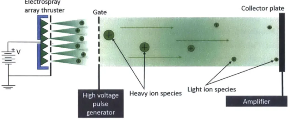
at these speeds is therefore not a trivial matter. A common technique used is the time-of-flight (TOF). This method uses an electrostatic or similar gate to quickly interrupt the ion beam being emitted. The ions present in the beam are not all identical, some of them are pure ions, and others are a neutral molecule attached to an ion. There can even be droplets in the jet. The different species of ions being emitted have different charge to mass ratios and therefore are expelled with different velocities. The heavier species have a lower velocity than the faster single ion species. Ions are collected on a collector plate that sits a significant distance from the thruster. Since the time at which the stopping gate is activated is known, it is possible to measure the time it takes for the ions to be collected on the collector plate. This is seen as a current that it is then boosted by an amplifier.
As it can be appreciated in the diagram, the heavier and therefore slower ion species will take longer to arrive to the collector plate once the beam has been blocked by the electric field produced in the gate. The separation distance from the gate to the collector plate defines the
resolution in time that the TOF signal will produce, larger distances allow less stringent timing requirements on the amplifier.
Electrospray
array thruster Gate Collector plate
Heavy ion species
Figure 2.3 Basic schematic of a TOF system
Several challenges appear with TOF measurements. Since the ion beam emitted from the thruster diverges, only a fraction of the total current actually makes it to the collector plate. This low current makes the design of the transimpedance amplifier an important endeavor. In addition its time
response must be fast enough to be able to detect all ion species. TOF measurements provide information about the different velocity of ions being emitted. If the energy of the ions is known, TOF can provide the expected specific impulse of the device.
2.3 Spacecraft charging effects
Specific impulse and thrust are the most important performance parameters of a thruster. They are characteristics intrinsic to each type of propulsion device. Chemical propulsion produce vibrations and extreme temperature swings near the nozzle. Similarly electric propulsion produces undesirable effects on its host spacecraft under certain scenarios. One of the most important process that is to be understood and its effects mitigated is spacecraft charging.
Spacecraft charging occurs when there is a current imbalance of electric currents from the spacecraft to the environment. In space, the environment is usually a low density plasma which interacts electrically with the satellite. Electrons and positive ions present in the plasma can collide with the spacecraft and deposit their charge. At the same time, backscattered
and secondary electrons are leaving the spacecraft and carrying their negative charge with them. Lastly, photo-emitted electrons also leave the spacecraft [7]. In a non-charging scenario all these currents balance out and the satellite stabilizes at a safe potential and does not charge. If there is an imbalance, the satellite can then charge positively or negatively, depending on a multitude of variables. Spacecraft charging can in some situations damage or tamper with scientific instruments aboard the satellite, in severe cases it can cause the mission to fail.
2.3.1 Scenarios
Electrospray thrusters provide thrust by ejecting ions. As it was
discussed previously, spacecraft charging occurs when there is an imbalance of currents arriving and leaving the spacecraft. If a spacecraft with an electrospray thruster emits only positive ions, it will lose some positive charge as it does. The loss of positive charge will make the satellite charge up negatively. To avoid charging, iEPS devices are designed to be fired in pairs. While one thruster emits positive ions, its partner will emit negative ions. If the two thrusters emit the same amount of ions, the emitted currents will cancel out and the spacecraft will not charge.
Intercepted
conncte inseres he amcurrent mutraethogbthfte,
+1kV
ensuring a n~~~~~~~~~eutral particle ba opsdo h aeaon fpstv bea
1e
W
Figure 2.4 Firing schematic for an iEPS pair As shown oil the figure above the iEPS design relies on a series connection to establish equal currents on both thrusters. Since they are connected in series the same current must travel through both of them, ensuring a neutral particle beam composed of the same amount of positive and negative charges.
If the ionic currents were not the same and the spacecraft started
charging, there is a possibility for some of the low energy ions to be attracted to the satellite due to its potential, collide with it and deposit their charge.
2.3.2 Self-regulating mechanisms
Spacecraft charging is to be avoided. If not controlled, the excess charge could cause electrostatic discharges that damage sensitive electronics. There are certain processes that are theorized to limit the potential which the spacecraft can reach while operating electrospray thrusters. A key aspect that allows this self-regulating mechanisms to occur is the interception
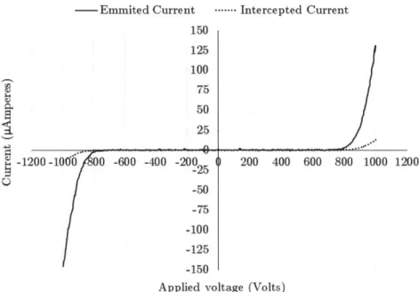
current. When an electrospray emits ions through the extractor aperture most of them make it out and provide thrust, a small fraction is collected on the extractor itself and do not produce thrust. Therefore it is beneficial to lower this interception as much as possible. A diagram of this process can be seen in Figure 2.4. Interception current is mainly dependent on the alignment of the apertures in the extractor grid with respect of the tips below. The shape of the emitter tips and the extractor itself also affects the amount of interception. During assembly, small differences in the alignment produce slightly different interception fractions.
Emmited Current 150 125 100 75 50 25 ...- Intercepted Current 00 -10O6 0 -600 -400 -200 ) 200 400 600 800 1000 -25 -50 -75 -100 -125 -150
Applied voltage (Volts)
Figure 2.5 Sample IV curve including intercepted current
In order to better explain the self-regulating mechanisms that limit spacecraft charging, it is helpful to present the next figure.
Figure 2.6 contains two electrospray thrusters simplified by the black arrows. The thrusters are connected in series to ensure the ionic currents are identical in steady state.
In a simplistic hypothetical example, assume thruster number one, T1, has a higher interception current fraction than T2. When the high voltage power supplies are energized and the thruster start emitting ions, positive ions coming from T1 will start collecting on the extractor more than the negative ions on T2. Since the extractor is electrically floating with respect to the high voltage power supplies, it will start to charge to a positive
potential. The previous process neglects secondary emission electrons that may be generated as the ions hit the extractor. As the extractor charges positively, the difference in potential from Ti with respect to the extractor is going to diminish. At the same time, the potential difference between T2 and the extractor will increase. Electrosprays have a strong proportional correlation between emitted current and applied potential. Since TI is now being actuated by a lower potential, it will start emitting less current.
Similarly T2 will start emitting more current due the increase of potential of T2 with respect to the extractor. As stated earlier, the interception current is a function of the total emitted current, Figure 2.5, since T2 is now emitting more current than T1, there are more negative ions being collected on the extractor. There is a point where the amount of positive and negative ions collected in the extractor is identical, and therefore the extractor stops charging. This process can be better visualized in Figure 2.6.
0
40
TI Electrically T2 + floating ---V
TI Current T2 Current 0 -V - Potential of TI w/r to Extractor - Potential of T2 w/r to Extractor - Potential of Extractor - -- T1 Current - -- T2 Current TimeFigure 2.6 Basic firing diagram of iEPS devices
Besides the interception current, there are other methods in which the satellite can self-regulate or limit the charging potential. If the spacecraft charges, a certain polarity of the emitted ions will be attracted to the satellite. If the potential of the spacecraft is higher than the emission potential of the lower energy ions, then ions will come back and deposit their charge on the structure. The low energy ions that make it back will not produce thrust but will aid in the neutralization of the spacecraft.
Lastly, if the satellite charges to potentials comparable to the ones being applied to the thrusters, there are certain scenarios in which a single
thruster would stop emitting completely while its partner accelerates species to higher energies.
3 Magnetically levitated testbed
The previous chapter focused on the performance parameters that directly impact the characteristics of electrospray thrusters. This section will focus in the instrument conceived to characterize electrosprays thrusters as a complete system. This instrument intends to elevate the Technology Readiness Level (TRL) of the
iEPS
design by testing the integrated iEPS system in a relevant environment, including driving electronics. Measuring thrust levels in the order of few ptNewtons, along with other parameters is performed using a Magnetically Levitated Thrust Balance (MLTB).3.1 Concept and innovations
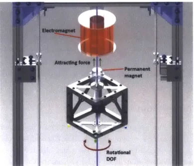
The idea for this instrument is simple: levitate a CubeSat using magnetic fields inside a vacuum chamber. The CubeSat is a totally standalone unit equipped with computers, radio, high voltage electronics and thrusters. While levitated and under vacuum the CubeSat can rotate freely around a single degree of freedom (DOF), Figure 3.1. Thrusters are fired remotely causing the satellite to rotate, the movement can be analyzed and thrust calculated.
In 1847, Ernshaw [8] established that stable magnetic levitation is impossible while utilizing only permanent magnets. For this reason, the
MLTB needs an active actuator, an electromagnet that is controlled by a levitation algorithm. A permanent magnet attached to the CubeSat is attracted by the previously mentioned electromagnet placed directly above it.
The 5 remaining DOFs are constrained to some degree by the magnetic force trying to align the two magnetic dipoles together. Using this setup allows the levitated satellite to rotate 360 degrees about the zero-friction DOF. This simple attribute constitutes an important advantage over the classical torsional balance. In a torsional balance, the thruster system sits on a platform suspended by a long fiber or very low stiffness joints. The thrust produced by the engines induces a torque on the joints and the deflection is then correlated with thrust. Since the joints have non-zero rotational stiffness the platform movement will be limited by the thrust the
propulsion devices generate. A 360 degree rotation allows a more complete study of the propulsion device acting as an attitude control actuator.
Figure 3.1 Exploited degree of freedom shown in blue
The complete isolation of the levitated CubeSat is also useful while trying to measure certain performance characteristics. Spacecraft charging effects can be accurately measured while the thrusters are firing using non-contact charge sensors. The thermal behavior of the levitated spacecraft can also be accurately measured taking advantage of the complete isolation to the outside environment. A final thing to mention is that the levitation system is extremely sensitive to the satellite weight. The magnetic force generated by the electromagnet is proportional to the current passing through its windings. It is clear that if the current on the coil can be accurately measured then a correlation with the levitated object weight can be made. Anufriev [9] has taken advantage of this fact to build a
magnetically levitated balance with sensitivities as low as 0.02 milligrams. Such high sensitivity to weight can be used to measure the propellant consumption of the satellite through time. If the propellant flow rate can be calculated and thrust measurements are also available, specific impulse can then be calculated.
3.1.1 Design
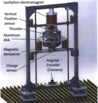
The main challenge faced by the system was the non-contact constraint and the vacuum safe requirements of all components. The final design consists of an extruded aluminum frame that houses all the actuators and sensors that are necessary for operation Figure 3.2. The frame is roughly 0.7 meters long, 1.3 meters tall and 0.5 meters wide. The electromagnet sits at the top of the structure. An aluminum bar extending from side to side of the structure is used to house the vertical position sensor, an essential part of the instrument. The support for the vertical position sensor is mounted on threaded rods that allow to adjust its vertical position with respect to the electromagnet. The position of the sensor dictates the stability of the levitated object and more importantly the amount of current necessary for the electromagnet to achieve levitation.
Figure 3.2 CAD render of the magnetically levitated thrust balance
The CubeSat is designed to be as close as possible as the CubeSat standard developed at the California State Polytechnic University [2]. The
electromagnet. Below the levitated CubeSat there is an aluminum bar extending from side to side of the frame which houses a spacecraft charge sensor and an electromagnetic damper used to brake oscillations present in the instrument. On the bottom side of the frame a camera acts as an angular encoder tracking four fiducial markers located on the bottom of the CubeSat. The whole system sits on top of spring dampers that rest on the vacuum chamber floor.
3.1.2 Thrust measurement
Having a zero friction environment where iEPS thrusters can be tested
opens several options for accurate thrust measurement. Thrust produced by the propulsion devices will translate in a torque applied to the satellite. Measuring the torque will have a direct correlation on the thrust produced
by the electrospray thrusters. In order to measure this correlation several
options are available.
The first method is to fire the thrusters for a specific amount of time and measure the change in angular velocity of the levitated satellite.
According to equation ( 3.1 ) the change in angular velocity of the levitated CubeSat, Aw is proportional to the time the thrusters fire and the amount of thrust provided, F. The time of the burn and the change in velocity can be determined with high accuracy. The moment of inertia, I, of the satellite and the lever arm at which the thrusters act, r, are the main parameters that introduce error to the measurement.
= IFdt (3.1)
In order for equation (3.1) to hold, the thruster pair must produce torque along the moment of inertia axis. The thrusters are mounted equally spaced from the middle axis of the satellite. If the geometric axis of the satellite does not align with the inertia axis the lever arm used for the calculation will not be accurate.
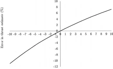
A preliminary error analysis was performed to establish the effects
certain variables had on the final thrust measurement. Assuming constant values close to the final design parameters and introducing error in certain
variables, error in one variable was correlated with error in total thrust measured. The parameters assumed where:
- Firing time of 10 minutes
- Moment of inertia of 0.001 kg/m^2
- Change in angular velocity from stationary to 10 RPM - Lever arm of 50 millimeters
- Total thrust baseline of 40 ptNewtons, equal to two thrusters being fired simultaneously
The torque lever arm corresponds to the difference between the geometric axis of the spacecraft and the moment of inertia axis. The following plot shows the total error in the thrust measurement assuming a lever arm of around 50 millimeters. Error was introduced in the lever arm length variable and the results shown below.
10 8 6 -10 -9 -8 -7 -6 -5 -4 -3 -2 ) 1 2 3 4 5 6 7 8 9 10 -2 0 -4 -6 -10 -12
Error in lever arm length(mm)
Figure 3.3 Sensitivity of thrust measurement with lever arm length
Following a similar scenario but now introducing the error to the moment of inertia value the following plot was generated.
5 3 A 2 .5 -0.1 -0.08 -0.06 -0.04 -0.02 ) .02 0.04 0.06 0.08 0.1 W -1 0 r4 -2 -3 -4 -5
Error in moment of inertia estimate(grams/m^2)
Figure 3.4 Sensitivity of thrust measurement with moment of inertia
In both cases the errors do not grow beyond a few of piNewtons, assuming flexible tolerances for both moment of inertia and lever arm measurements. To measure moment of inertia and lever arm length one could use traditional methods or specialized instruments, the latter provide better accuracy. COTS moment of inertia and center of gravity
determination instruments such as the KSR series from Space Electronics
LLC [10] have accuracies of 0.1% for moment of inertia determination. The
same instrument possess a center of gravity location accuracy down to 25 pMeters. If such an instrument were to measure the moment of inertia and center of gravity location of the CubeSat, the thrust estimate error
(assuming zero error on the other variables and no environmental effects) would be fractions of a pNewton.
The second method to estimate thrust is based on COTS force probes. Companies such as Femto Tools [11], produce micro force sensor probes with force ranges going from 0 to 100 pNewtons. The company states a resolution of 5 NanoNewtons at 10Hz. The precision declared for this probes is substantial, and a pair of probes could be used to measure thrust directly in the zero friction environment of the levitated CubeSat. A probe pair could be carefully positioned such that the probes counteract the torque produced by the thrusters. If such a setup could be constructed and the
accuracies of the probes are the ones stated by the company, final thrust measurements could have accuracies in the order of NanoNewtons.
Figure 3.5 FTS-100, a micro force probe sensor
The third method to measure thrust taking advantage of the zero friction environment, is the one followed by standard torsional balances designers. An actuator that provides calibrated forces in the order of the thrust produced by the thrusters is used to counteract the torque induced in the balance arm. Commanding the thrusters to fire and modulating the calibration force until the satellite remains stationary (thrust force is equal to calibration force) yields the thrust measurement. This method difficulty relies on the calibration force analysis and construction of the actuator. The method has been extensively studied and will remove some of the desirable attributes of the MLTB. Further details on this topic are outside the range of this document and can be approached further in [6].
3.2 Sensors and actuators
The MLTB is designed to operate inside a vacuum chamber. The materials used in the design must have low outgassing in vacuum.
Disregard of this constraint could lead to vacuum chamber contamination and deposition of volatile materials that could, in some instances,
deteriorate the vacuum level reached by the chamber. This sole requirement proved important when choosing materials for constructions as well as electronics. The majority of plastics tend to outgas in vacuum, special care had to be taken in order to choose only low outgassing plastics, such as Teflon.
Vacuum chamber connections for electrical power and data also required significant design in order to minimize cable losses and to achieve data integrity. Lastly, the non-contact characteristics of the sensors used disqualified most of the COTS sensors available on the market. In certain cases custom made sensors and actuators had to be fabricated due to the non-contact constrain or the vacuum compatibility of the materials
3.2.1 Main electromagnet
In order to sustain stable magnetic levitation an active controller system must be used [8]. To achieve this, an electromagnet is used as an actuator
and a vertical position sensor is used as a feedback signal to control the position of the levitated satellite. A custom made, vacuum safe,
electromagnet was fabricated due to lack of commercially available products. The electromagnet was sized to levitate a one kilogram object 1 centimeter away. This gap was necessary to position some sensors between the electromagnet and the levitated satellite. The magnetic actuator is wound around a solid steel core.
In order to keep the currents of the electromagnet low, a permanent magnet with a surface field of 5903 Gauss is attached to the CubeSat to provide a steady bias lifting force. The permanent magnet is attracted to the steel core of the electromagnet even when no current is flowing through the electromagnet coils. The bias force was taken into account to size both the electromagnet and the permanent magnet on the CubeSat.
Magnetostatic simulations were run in Maxwell V14 to verify the design against requirements. The final design produces around 10 Newtons of steady bias lifting force between the steel core of the electromagnet and the permanent magnet on the satellite.
Figure 3.6 Steady bias lifting force magnitude of permanent magnet, side view
Running one Ampere of current through the 2500 turns of copper wire used on the final electromagnet design provide an additional 11.7 Newton's of force, for a total of 21.8 Newton's of total lifting power.
Additionally the system must also be able to repel the CubeSat in the case that it gets too close to the steel core and the weight of the satellite is no longer sufficient to keep it separated. Running one Ampere of current in reverse provides a net repulsion force of around one Newton.
Figure 3.8 Repulsion force magnitude at one Ampere of current
3.2.2 Vertical position sensor
For the magnetic levitation controller to work, it needs a very accurate feedback signal containing information about the vertical position of the satellite with respect to the electromagnet resting on top. The controller will increase the current through the coils if the satellite is lower than the commanded set point. It will decrease the current if the satellite is higher than expected. By doing this thousands of times a second, stable levitation
can be achieved and the object will stay close to the desired height.
The non-contact constraint on the type of sensor used posed challenges to generate a high resolution signal of the position of the satellite. Several
attempts using magnets and Hall Effect sensors were made and proved to work. The final design relies on an optical shadow sensor based on the
sensor developed at Stanford University to control the test mass of the LISA mission [12]. The sensor uses two laser beams, (5 milliwatt and around 650 nanometers wavelength around 650 nanometers) that are semi obstructed by an optical flag attached to the levitated CubeSat.
Figure 3.9 Optical shadow sensor concept
As the satellite moves up and down, it obstructs more light on one of the beams and allows more light to pass on its counterpart. The light intensity is read by two light sensitive resistors connected in a series configuration. This connection allows for a very high resolution position readout.
3.3V
Laser I Laser 2 Figure 3.105V
Receiver I Receiver 2Optical shadow sensor electrical diagram
The sensor used for this instrument has an ultimate resolution of around
3 iMeters per bit, using a 10-bit Analogue to digital converter. The sensor
has 700 tMeters of useful linear range.
-Raw Signal .--- Linear fit
750 600 Z 450 3 300 -2 150 o. 0 ... _--1) 0.5 1 1.5 2..-.5 3 3.5 4 4.5 5 - -150 > -300 -450 -600 -' -750 Output signal(Volts)
Figure 3.11 Transfer function of optical shadow sensor The optical shadow sensor is mounted on a vertically adjustable aluminum bar that sits between the electromagnet and the satellite. The sensor is built around a square frame that allows all the components to stand far away from the levitated CubeSat. Since the position of the sensor is adjustable, the height at which the satellite nominally levitates can also be adjusted. If the bar is positioned such that the steady bias force of the permanent magnet is close to the satellite weight, then the electromagnet only has to disturb this state to ensure stable levitation. This feature allows the current of the electromagnet to be very small in some cases, as low as
100 milliamps when correctly adjusted. The electromagnet is kept cool by
using these low currents.
3.2.3 Angular encoder
In order to calculate thrust from the rotational motion of the levitated satellite, the angular position of the CubeSat over time has to be known. In