Publisher’s version / Version de l'éditeur:
Vous avez des questions? Nous pouvons vous aider. Pour communiquer directement avec un auteur, consultez la
première page de la revue dans laquelle son article a été publié afin de trouver ses coordonnées. Si vous n’arrivez pas à les repérer, communiquez avec nous à PublicationsArchive-ArchivesPublications@nrc-cnrc.gc.ca.
Questions? Contact the NRC Publications Archive team at
PublicationsArchive-ArchivesPublications@nrc-cnrc.gc.ca. If you wish to email the authors directly, please see the first page of the publication for their contact information.
https://publications-cnrc.canada.ca/fra/droits
L’accès à ce site Web et l’utilisation de son contenu sont assujettis aux conditions présentées dans le site
LISEZ CES CONDITIONS ATTENTIVEMENT AVANT D’UTILISER CE SITE WEB.
International No-Dig 2003 Conference [Proceedings], pp. 1-14, 2003-03-01
READ THESE TERMS AND CONDITIONS CAREFULLY BEFORE USING THIS WEBSITE. https://nrc-publications.canada.ca/eng/copyright
NRC Publications Archive Record / Notice des Archives des publications du CNRC :
https://nrc-publications.canada.ca/eng/view/object/?id=41d83fbc-2e89-4a9d-9db2-0f5bbbe3e7fe https://publications-cnrc.canada.ca/fra/voir/objet/?id=41d83fbc-2e89-4a9d-9db2-0f5bbbe3e7fe
NRC Publications Archive
Archives des publications du CNRC
This publication could be one of several versions: author’s original, accepted manuscript or the publisher’s version. / La version de cette publication peut être l’une des suivantes : la version prépublication de l’auteur, la version acceptée du manuscrit ou la version de l’éditeur.
Access and use of this website and the material on it are subject to the Terms and Conditions set forth at
Behavior and performance of liner pipe in trenchless and trenched portions of sliplining rehabilitation
Behavior and performance of liner pipe in trenchless and trenched portions of sliplining rehabilitation
Zhao, J.Q.; Doherty, I.J.
NRCC-46292
A version of this document is published in / Une version de ce document se trouve dans :
International No-Dig 2003 Conference, Las Vegas, Nevada, March 31-April 2, 2003, pp. 1-14
BEHAVIOR AND PERFORMANCE OF LINER PIPE IN TRENCHLESS
AND TRENCHED PORTIONS OF SLIPLINING REHABILITATION
Jack Q. Zhao, Ph.D., P.Eng. Institute for Research in Construction
National Research Council Canada, Ottawa, ON, Canada and
Ian J. Doherty, P.Eng.
Trenchless Design Engineering Ltd., Toronto, ON, Canada
ABSTRACT
Although the majority length of a liner pipe in sliplining rehabilitation is installed without excavation, some portions of the pipe are installed by the open-cut method at locations where connections cannot be made otherwise. The pipe undergoes a sudden change in loading
condition, bedding condition and pipe ring composition when it passes through installation pits. A thorough understanding of these changes and how they affect the behaviour and performance of the installed pipe is necessary for effective designs that lead to satisfactory long-term
performance. This paper presents an analysis of trenched and trenchless portions of grouted and ungrouted sliplined pipes. Liner pipe materials investigated include HDPE, PVC and reinforced fibreglass. Comparison are made between the trenchless and the trenched portions of the liner pipe in terms of loading, responses to load, effect of bedding and service life. A critical length is defined for the trenched portion in which joints should be avoided, and a practical formula is proposed for determining the critical length. The approach is illustrated by an example of a 915 mm (36”) HDPE sliplined watermain.
Keywords: behaviour, performance, sliplining, liner pipe, loading, trenchless, trenched portion,
INTRODUCTION
Continuous sliplining is one of the trenchless technologies that can be used to rehabilitate watermains and sewers. Much research and many case studies have been focused on the performance and design of composite pipes with a liner inside a host pipe [1,2,3,4,5,6].
However, less attention in a trenchless installation is given to certain locations outside the host pipe where the slipliner pipe effectively becomes a trenched installation. Such locations include:
• Connection of two segments of slipliner inserted from opposite directions (Fig. 1a). At such a location, joining of the segments is carried out using methods such as flanging, or
electrofusion couplings in open excavation.
• T-connection or elbow or a sudden change in direction or elevation (Fig. 1b). Similarly, flanges may need to be fused to the pipe ends and bolts may be required to make the connection.
• Connection between two different sizes or between the plastic liner pipe and a pipe of different material (Fig. 1c).
• Other places (such as lateral connections) where the connection cannot be effectively made from inside the pipe.
• Locations where existing bend fittings are eliminated by bending the flexible liner pipe in a curve outside the host pipe.
At these locations, not only is the portion of the pipe in the excavation (referred to as “trenched portion” as opposed to “trenchless portion”) subjected to different loading effects, but also the pipe system and its behavior are different than in the trenchless portions. The liner pipe
undergoes a sudden change in response to different loads when it goes from inside the host pipe into a backfilled pit. While the trenchless portions are separated from the soil environment by the host pipe (and the grout, if used), the trenched portions are subjected to direct interaction with the surrounding soils.
This paper presents a practical analysis and a comparison between the trenchless and the trenched portions of the pipe in terms of loading conditions, behavior and quality of bedding. Better understanding of the behaviour and performance of liner pipes in trenchless and trenched portions will help minimise the possibility of weak points in the buried pipeline within trench reinstatements. This increased knowledge will lead to more effective and innovative designs in future sliplining (and possibly other structural lining) projects and to improved performance of the overall rehabilitation.
DIFFERENCES IN EXTERNAL LOADING
When sliplining technology is used to rehabilitate a partially deteriorated rigid pipe (such as cast iron, vitrified clay pipe or concrete pipe), the earth loads on the host rigid pipe can be determined by the Marston trench load theory [7] on rigid pipe as:
(1) 2 c d RIGID C B W = γ
(2)
H
Trenchless Transition Zone
Trenched Trenchless Transition Zone
a) Insertion Pit (section) b) T - connection (plan) Trenched Extent of Excavation Trenched Larger or other type of pipe c) Connection to a larger pipe,
or a different material pipe (section)
Liner pipe Liner pipe inside host pipe ' ' 2 1 ' ' 2 µ µ k e C d B h k d − − =
Fig. 1. Locations of trenched sections in sliplining rehabilitation
where WRIGID = earth load per unit length, Cd = load factor, γ = unit weight of soil backfill
above the pipe, Bd = trench width at top of pipe for trench condition, k′ = Rankine’s active ratio
of lateral to vertical soil pressure, h = height of soil backfill above the pipe, and µ′ =coefficient of friction between backfill material and the sides of the trench. For flexible pipe, the external soil load is taken as the prism soil load:
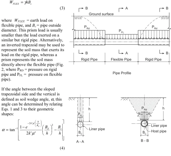
(3) where WFLEX = earth load on
flexible pipe, and Bc = pipe outside
diameter. This prism load is usually smaller than the load exerted on a similar but rigid pipe. Alternatively, an inverted trapezoid may be used to represent the soil mass that exerts its load on the rigid pipe, whereas a prism represents the soil mass directly above the flexible pipe (Fig. 2, where PRD = pressure on rigid
pipe and PFL = pressure on flexible
pipe).
If the angle between the sloped trapezoidal side and the vertical is defined as soil wedge angle, α, this angle can be determined by relating Eqs. 1 and 3 to their geometric shapes:
(4)
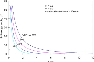
Fig. 2. Soil loading on rigid and flexible pipe This angle is a measure of the extra load on a rigid pipe versus that on a flexible pipe in an open-cut installation. The larger the angle, the higher the extra load on the rigid pipe. Fig. 3 is a plot of
− − = − − h B h B k e B d c h k d 2 ' ' 2 1 ' ' 2 1 tan µ α µ c FLEX hB W =γ B A B Ground surface B A B Rigid Pipe Flexible Pipe Rigid Pipe Pipe Profile PRd PRd PFL PFL h BC A - A Liner pipe Liner pipe PRd h BC a a B - B Host pipe
soil wedge angle vs. ratio of trench depth to width. The assumptions used for calculating the angle are indicated in the figure. In general, the soil wedge angle decreases with increase in pipe size for the same h/Bd value.
Soil loads in the trenchless portions act only on the host pipe as long as it retains its structural integrity, regardless of a grouted or ungrouted annulus. This is because the liner pipe is inserted while the host pipe is subject to full soil loading. However, if the groundwater table is above the pipe invert, the liner pipe may be subjected to external hydrostatic loading due to seepage of groundwater through defects in the host pipe. In the case of a grouted annulus, the liner pipe shares only a small portion of the external surface live loads [6]. The load portion shared by the liner pipe depends on pipe stiffness factors of the three pipe rings involved in the grouted sliplined pipe.
In a pressurized pipe, the internal hydrostatic load is taken solely by the liner pipe in the ungrouted case. In the grouted case, the internal load is distributed to the host pipe, the grout ring and the liner pipe according to their rigidity factors [6]. In such a case, the higher the rigidity factor of the liner pipe, the higher the load on the liner pipe. These load
differences are illustrated in the example at the end of this paper.
DIFFERENCES IN DEFORMATION
Ring deformation of liner pipe, trenched portion
The deformation of a pipe in the trenched portion is caused by internal pressures and external loads. The internal load expands or contracts the pipe radially, while the external load deforms the pipe into a non-circular shape. The diameter change (∆D) due to internal pressure can be
determined as:
(5)
where D = mean pipe diameter, E = elastic modulus of pipe material, t = wall thickness, k = stiffness modulus of elastic soil foundation, and P = internal pressure. In Eq. 5, the support of the surrounding soil is taken into account by the modulus of soil reaction, which is assumed to be constant around the pipe. Under external soil loading, a circular flexible pipe is commonly assumed to deform into an ellipse and its deformation is determined by the Spangler’s equation [8]: P kD Et D D 2 2 2 2 + = ∆ 0 10 20 30 40 50 60 0 2 4 6 8 10 12 h/Bd S o il wedge angle, α º OD=100 mm 300 600 983 k' = 0.3 u' = 0.3
trench side clearance = 150 mm
(6)
(7)
where DL = deflection lag factor, K = bedding constant, E′ = modulus of soil reaction, WFLEX =
uniform external load, I = moment of inertia of pipe wall, r = mean radius, ∆x = horizontal
diameter increase, and ∆y = vertical diameter decrease.
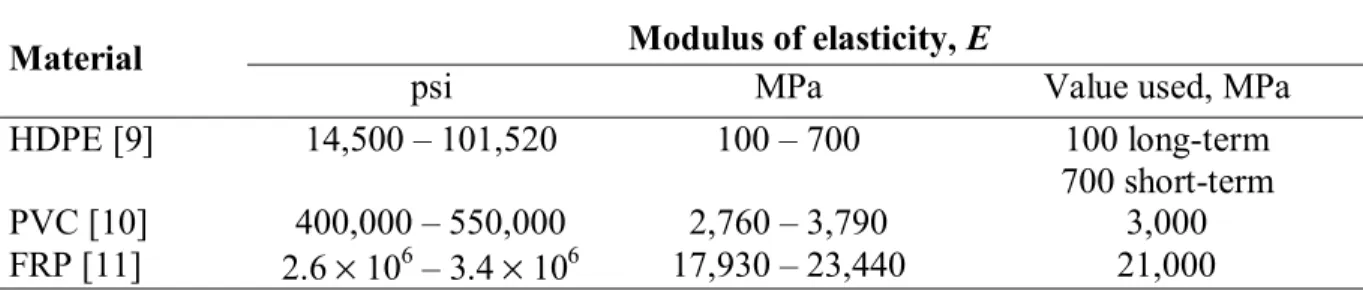
As shown in Eqs. 5 and 6, pipe deformations depend on not only on a pipe’s dimensions and properties but also on the modulus of soil reaction. Slipliner pipe materials include high density polyethylene (HDPE), PVC and fibre-reinforced plastic (FRP, or fibreglass) pipes, each having its own material properties. Table 1 shows the ranges of modulus of elasticity of these materials. The values representing these materials are used in this study. The short- and long-term values of HDPE pipe are used to illustrate the effect of plastic relaxation.
Table 1. Modulus of elasticity of HDPE, PVC and FRP
Modulus of elasticity, E Material
psi MPa Value used, MPa
HDPE [9] 14,500 – 101,520 100 – 700 100 long-term 700 short-term PVC [10] 400,000 – 550,000 2,760 – 3,790 3,000 FRP [11] 2.6 × 10⁶ – 3.4 × 10⁶ 17,930 – 23,440 21,000
Quality of soil bedding, which depends on soil type and degree of compaction, is represented by the modulus of soil reaction [8]. Howard et al. [12] provide average values of modulus of soil reaction for different soil types and four degrees of compaction. Four representative values of E′ are used for this study (Table 2).
The stiffness modulus of elastic soil foundation (k) is related to the quality of bedding (E′) by: (8)
When the circular cross-section of a pipe changes to an ellipse, the moment of inertia of the cross-section also changes. This moment of inertia (Ix) can be determined as:
(9) FLEX L W r E EI Kr D x 3 3 ' 061 . 0 + = ∆ x y = ∆ ∆ 1.0953 −∆ +∆ − −∆ +∆ = 3 3 2 2 2 2 4 y ID x ID y OD x OD Ix π ' E r B k = c
where OD and ID are outside and inside diameters. The effect of the modulus of soil reaction is most noticeable when E′ is less than 2 MPa (290 psi). For E′ = 7 MPa (1,000 psi), the pipe’s moments of inertia are almost identical for all three pipe materials. For stiff pipe like that made from FRP (E = 21,000 MPa), the modulus of soil reaction has no effect on the pipe’s moment of inertia.
Ring deformation of liner pipe, trenchless portion
There are two situations to consider: (a) ungrouted and (b) grouted. In the case of ungrouted sliplining, the ring deformation of the liner is due to internal and external hydrostatic loads only. This deformation can be determined using Eq. 5 and setting k = 0. In non-pressurized
applications, the liner pipe does not experience much deformation except for situations where groundwater tables are significantly above the pipe. In such cases, the liner pipe needs to be designed against buckling failure [14]. In the case of grouted sliplining, ring deformations of the liner pipe can be determined for the applicable portions of the external and internal loads. These cases are illustrated in the example given below.
Table 2. Modulus of soil reaction, soil types and compaction levels [12] E′
Description of bedding soil
psi MPa
Fine-grained soils (LL>50), CH†, MH, CH-MH 1 0.007 Fine-grained soils (LL<50), with less than 25% coarse-grained particles,
no compaction (dumped), CL, ML, ML-CL
50 0.34 Fine-grained soils (LL<50), with more than 25% coarse-grained particles,
dumped, CL, ML, ML-CL
Coarse-grained soils with fines, no compaction, GM, GC, SM, SC
100 0.7
Fine-grained soils (LL<50), with less than 25% coarse-grained particles, >95%‡ compaction, CL, ML, ML-CL
Fine-grained soils (LL<50), with more than 25% coarse-grained particles, 85%-95% compaction, CL, ML, ML-CL
Coarse-grained soils with fines, 85%-95% compaction, GM, GC, SM, SC Coarse-grained soils, little fines, <85% compaction, GW, GP, SW, SP Crushed rock, dumped
1,000 7
† - ASTM D 2487 [13] designations. ‡ - compaction in terms of maximum dry density.
PIPE DEFLECTION ALONG LONGITUDINAL DIRECTION
Liner pipe deflection along longitudinal direction, trenched portion
The trenched portion of a sliplined pipe can be treated as a beam on an elastic foundation. The ends can be treated as having fixed supports because the liner pipe continues from trenched into the trenchless configuration. The governing equation for such a problem [15] is:
(10) x FLEX x EI W y EI k dx y d = + 4 4
where y = vertical deflection along the pipe, and x = distance from the support (other terms are as defined above). Pipe vertical deflection (y), vertical moment (M) and shear force (Q) can be obtained by solving Eq. 10 as shown in Figs. 4 and 5. The applied load represents a soil prism of 2 m depth with a unit weight of 18 kN/m3. The length of the trenched pipe portion is 5 m. Pipe deflection curves for E =100, 700, 3,000 and 21,000 MPa are shown in Fig. 4 for E′ = 0.7 MPa (100 psi). Maximum deflections vary with the modulus of soil reaction and the modulus of elasticity of the pipe. For E′ = 0.7 MPa (poor quality bedding), the maximum deflection of the pipes with E = 100, 700 and 3, 000 MPa reaches 2.5% of its diameter (Fig. 4).
For the stiffer pipe (E = 21,000 MPa), the maximum deflection is 1.1% of its diameter. Pipes with smaller moduli attain a
maximum deflection at a shorter distance from the end support. The maximum deflection/diameter ratio of all four pipes is 0.25% for high quality bedding (E′ = 7 MPa). The moduli of
elasticity of plastic pipes are known to decrease with time [16]. It follows that pipe deflection profiles change with time.
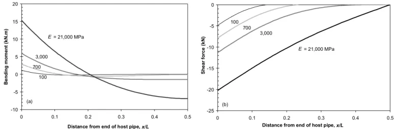
Vertical bending moments are shown for E′ = 0.7 MPa (100 psi) in Fig. 5a. The curve for E = 21,000 MPa is similar to that of a beam without foundation support. With foundation support, moments reduce drastically as distance increases from the end support for E = 100, 700 and 3,000 MPa. Similar observations can be made from different E′ -values. In general, an increase in soil support (i.e., increase in E′) reduces moments in a pipe. Good soil support reduces the negative moments to about zero in the middle of the pipe. Therefore, the higher the quality of bedding, the better the performance of the pipe. Furthermore, a decrease in E with time will result in a decrease in moment.
-3 -2.5 -2 -1.5 -1 -0.5 0 0 0.1 0.2 0.3 0.4 0.5
Normalized longitudinal distance, x/L
Ver ti cal def lect ion of pi pe, y/ D (% ) E = 21,000 MPa 3,000 700 100
Fig. 5. Moments and shear forces for E′ = 0.7 MPa (100 psi)
Vertical shear forces for E′ = 0.7 MPa (100 psi) are shown in Fig. 5b. High shear forces occur near the end supports. The curves show that shear forces reduce quickly as distance from the end support increases. In general, the higher the bedding quality, the smaller the shear forces in the pipe.
CRITICAL ZONES
Observations of high moments and high shear forces near the end supports within a trenched portion lead to the definition of “critical zones”. This zone is defined by the critical length (xc) at
which a moment curve crosses the zero-line. The regions defined by x = 0 and x = xc and by x = L- xc and x = L are defined here as the critical zones (L is the total length of a trenched portion).
One of the reasons for having a trenched portion is for joining liner pipe segments. It would then be highly desirable to locate the joints outside the critical zones, thus avoiding the combined effects of the potential joining
imperfection and higher stresses. Improperly-made joints may be weak links in the pipeline [17]. The critical length can be found analytically, however, the solution is rather complicated. By expanding the cos-, sin-, sinh- and cosh-terms and ignoring their higher order terms, an approximate formula has been derived as: (11) where L EI k x = 4 4 φ ) cos( ) cosh( ) sin( ) sinh( 2 1 φ φ φ φ φ − − = L xc 0 0.02 0.04 0.06 0.08 0.1 0.12 0.14 0.16 0.18 0.2 0 5 10 15 20
Modulus of soil reaction, E' (MPa)
C rit ic a l xc /L E = 21,000 MPa 3,000 700 100
Fig. 6. Effect of modulus of soil reaction on critical length
-10 -5 0 5 10 15 20 0 0.1 0.2 0.3 0.4 0.5
Distance from end of host pipe, x/L
Be nding m o m e nt ( k N.m ) E = 21,000 MPa 3,000 700 100 (a) -25 -20 -15 -10 -5 0 0 0.1 0.2 0.3 0.4 0.5
Distance from end of host pipe, x/L
Sh ear fo rc e (kN ) 100 3,000 E = 21,000 MPa 700 (b)
The effects of Young’s modulus (E) of the pipe and the section modulus of the pipe (Ix) are
included in Eq. 11. The modulus of soil reaction (E′) is related to k (Eq. 8).
Fig. 6. shows the relationship between xc/L and E′ and E as determined by Eq. 11. The critical
length, xc/L decreases and approaches a constant value as the modulus of soil reaction E′
increases, for all pipe materials. In other words, higher quality bedding means shorter critical lengths. The impact of the quality of bedding on the critical length levels off when E′ > 7 MPa. On the other hand, a stiffer pipe has a larger xc/L. The decrease in E with time has the benefit of
reducing the critical length.
Pipe deflection along longitudinal direction, trenchless portion
Inside the host pipe, the trenchless portions of the liner pipe follow the host pipe’s profile. In the case of ungrouted sliplining, buoyancy may cause upward deflection of a gravity pipe in
locations with a high groundwater table [18]. In the case of grouted sliplining, the position of the liner pipe with respect to its host pipe is restrained by the grout. Thus, deflections of the liner pipe along the longitudinal direction are expected to be small and can be neglected in design. Discussions on service life
A host pipe provides a certain degree of protection for the trenchless portions (majority) of the liner pipe. A recent study has shown that the service life of a grouted sliplined pipe, even with no bonding at the interfaces of the pipe rings, would be increased [6]. This increase in service life is attributed to the increased remaining service life of the host pipe due to reduced loading, and to the delayed application of full loads on the liner pipe. Ungrouted sliplining may be best suited to non-pressurized pipe applications and in such cases the trenchless portions of the liner pipe are not subjected to internal loading. In general, less loading means longer service life.
In contrast, trenched portions of a liner pipe are subjected directly to the soil environment and to full external and internal loads. In addition, other elements, such as joints, connections, laterals, etc., may exist within the trenched portions. Sudden changes in loading and bedding support subject these portions to higher stresses than the trenchless portions. If mechanical joints are used, the metal parts (flanges, screws and nuts) are vulnerable to corrosion, which will
compromise the high corrosion resistance of the plastic pipe itself. Therefore, trenched portions must be properly designed so that the desired service life can be achieved throughout a sliplining rehabilitation.
AN EXAMPLE
A 910-mm (36”) (ID) cast iron watermain under Gloucester Street in downtown Ottawa is sliplined with an 840-mm (33”) (OD) HDPE pipe. The annulus is grouted with lightweight cementitious grout. The soil cover is 1.5 m (5 ft.) and has a unit weight of 18 kN/m3 (115 pcf). The pipe bedding and backfill is granular and compacted to 95% Proctor density. The
groundwater table is below the pipe. The dimensions and material properties of the three pipe rings in the pipe system are given in Table 3.
Comparison of loads
The trenched portions of the HDPE pipe are subjected to 100% of the soil load, the traffic load and the internal load (Table 4). In contrast, the ungrouted trenchless portions are subjected to 100% of the internal load only, whereas the grouted trenchless portions are subjected to 4% of the surface traffic load and 1.6% of the internal load (short-term response). Thus, the trenched portions are subjected to much higher loads than the trenchless portions.
Comparison of ring deformation
Since the bedding and backfill is granular and compacted to 95% Proctor density, the quality of bedding is high and could be represented by E′ = 7 MPa. From Eq. 8, the stiffness modulus of elastic soil foundation can be determined as k = 14.9 kN/m2. Diameter changes due to internal load (Eq. 5) are 0.046 to 0.047 mm for E = 100 to 700 MPa over time, respectively. Thus, the change in pipe’s modulus of elasticity does not have much impact on the diameter change due to the good soil support.
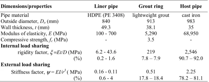
Table 3. Parameters and pipe stiffness and rigidity factors
Dimensions/properties Liner pipe Grout ring Host pipe
Pipe material HDPE (PE 3408) lightweight grout cast iron
Outside diameter, Do (mm) 840 913 983
Wall thickness, t (mm) 49.3 38.1 35
Modulus of elasticity, E (MPa) 100 - 700 5,290 68,950
Compressive strength, fc (MPa) - 3.5 -
Internal load sharing
rigidity factor, ξ =Et/D (MPa) 6.2 - 43.6 219 2,546 (%) 0.2 - 1.6 7.8 – 7.9 90.7 – 92.0
External load sharing
Stiffness factor, ψ = EI/r3 ( MPa) 0.16 - 0.11 0.51 2.25 (%) 0.6 - 4 17.8 – 18.4 78.2 – 81.1
Table 4. Summary of load differences on trenched and trenchless liner pipe
Trenchless portions Grouted
Load type Trenched
portions Ungrouted
short-term long-term
External soil (kN/m) 100% 0% 0% 0%
Surface traffic (kN/m) 100% 0% 4% 0.6%
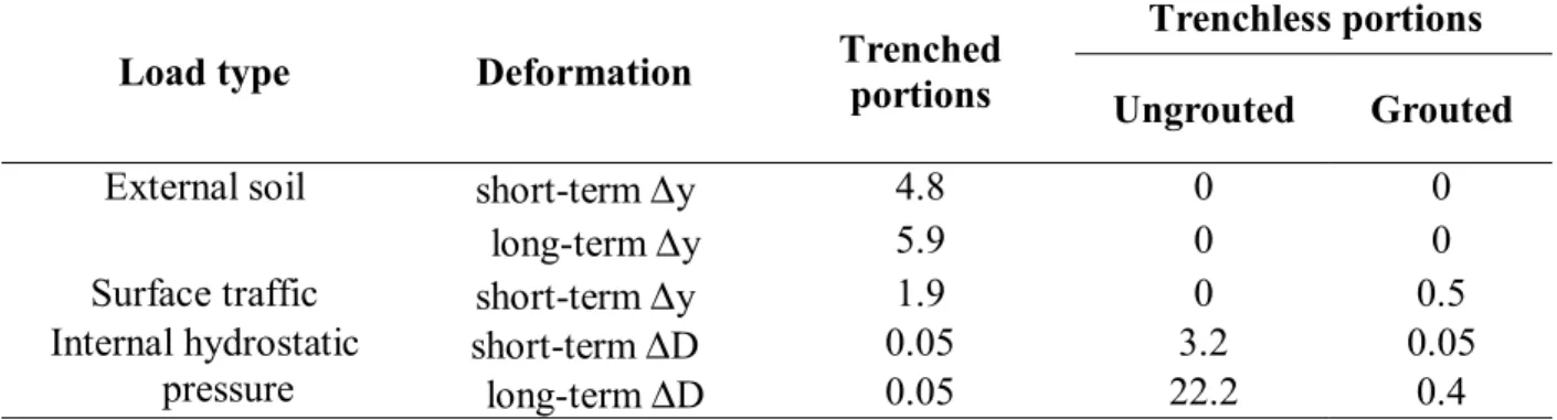
Internal hydrostatic (kPa) 100% 100% 1.6% 0.2% Ring deformations are summarized for short-term and long-term responses of the HDPE liner pipe in Table 5. With good soil support, the trenched portion is not subjected to large diameter increase under the internal pressure. In contrast, the ungrouted trenchless pipe would experience increases of from 3.2 to 22.2 mm in diameter for the short-term and a long-term response,
respectively. The trenchless pipe in grouted sliplining would undergo less than 1 mm increase in diameter or in vertical deflection due to surface traffic load.
Table 5. Comparison of ring deformations (mm) determined by Eqs. 6 and 7
Trenchless portions
Load type Deformation Trenched
portions Ungrouted Grouted
short-term ∆y 4.8 0 0
External soil
long-term ∆y 5.9 0 0
Surface traffic short-term ∆y 1.9 0 0.5
short-term ∆D 0.05 3.2 0.05
Internal hydrostatic
pressure long-term ∆D 0.05 22.2 0.4
Liner pipe deflection along longitudinal direction, trenched portion
Vertical deflection, moment and shear force of the trenched pipe portions along the longitudinal direction are shown in Fig. 7. The short-term and long-term responses are represented by E = 700 and 100 MPa, respectively. Using Eq. 11, the critical length can be determined:
Therefore, joints are best located within the middle 75% of the trenched length.
term) (long 07 . 0 or ) term (short 12 . 0 − − = L xc
Fig. 7. Pipe deflection, moment and shear diagrams
SUMMARY AND CONCLUSIONS
An analysis has been carried out on the loading and behavior differences between trenched and trenchless portions of a sliplined pipe. Trenched portions are inevitable at certain locations along a sliplined pipe. Adequate attention must be given to the trenched portions to ensure the same level of service life as the trenchless portions. HDPE, PVC and FRP pipes are considered in this study. Based on this study, following conclusions can be drawn:
• Trenched portions of a slipliner pipe behave differently from trenchless portions of the same pipe. While the trenchless portions are protected by the host pipe, the trenched portions are subjected directly to loads from the surrounding soils.
• Critical zones have been defined within the length of a trenched portion and a practical formula (Eq. 11) has been proposed to determine the critical length from the end of the host pipe. Within the critical length, there are high moments and shear forces, and therefore pipe joints should be located away from these critical zones.
• More flexible liner piping materials suffer less moment and shear in the trenched portions. Moments and shear forces within critical zones decease with decrease in pipe’s modulus of elasticity (with time). In addition, the critical length is also decreased.
• High quality bedding and backfill materials (E′≥ 7 MPa or 1,000 psi) should be used in the trenched zone to ensure satisfactory performance of the trenched portions.
-0.3 -0.2 -0.1 0
0 0.1 0.2 0.3 0.4 0.5 0.6 0.7 0.8 0.9 1
Distance from end of host pipe, x/L
P ip e ve rt ic al d e fl ec ti o n , y/ D (% ) E = 100 MPa 700 (a) -10 -5 0 5 10 15 20 0 0.1 0.2 0.3 0.4 0.5
Distance from end of host pipe, x/L
Mo me n t, M (k N .m ) (b) xc xc E = 700 MPa 100 short-term long-term -30 -25 -20 -15 -10 -5 0 0 0.1 0.2 0.3 0.4 0.5
Distance from end of host pipe, x/L
S h e a r fo rc e , Q (k N ) (c) E = 700 MPa 100
• Trenchless portions of a sliplined pipe are likely to have a longer service life than trenched portions. Good design of the trenched zone, including exits from the host pipe, location of joints and bedding and backfill will go a long way in minimizing the difference.
References
1. Meldt, R. The strength of HDPE pipes for the renovation of pipelines by sliplining. Proc. Int’l Conf. Plastics Pipes V, York, UK, Sept. 8-10, 1982. Plastics & Rubber Inst. pp. 37.1-37.11. 2. Björklund, I. and Janson, L-E. Swedish experience of the use of thermoplastic pipes for water
and sewage transport. Proc. of Int’l Conf. Underground Plastic Pipe, New Orleans, Louisiana, U.S.A., March 30 – April 1, 1981. ASCE, pp.385-400.
3. Mizell, L. and Petroff, L.J. Sliplining: design and installation considerations for polyethylene pipe. Proc. of Int’l Conf. Pipeline Infra. II, San Antonio, TX, Aug. 16-17, 1993, pp. 40-63. 4. Goddard, J.B. Plastic Pipe Design, Technical Report 4.103. Advanced Drainage Systems, Inc.,
(http://www.ads-pipe.com/techpapr/note4103.htmal), 1994, p.27.
5. Stephens, P.J. Project guidelines for slipline grouting. No-Dig Engineering, Vol. 3, No. 2, 1996. Trenchless Technology, Inc., Peninsula, OH, pp.2-4.
6. Zhao, J.Q. and Daigle, L. Structural performance of sliplined watermain. Can. J. of Civil Eng. 2001 vol. 28, No. 6, pp. 969 -978.
7. Marston, A. The Theory of External Loads on Closed Conduits in the Light of the Latest Experiments. Bulletin 96, Iowa Eng. Exp. Stn., Ames, Iowa. 1930, p.38
8. Moser, A.P. Buried Pipe Design. McGraw-Hill, Inc. New York, NY, 1990.
9. Driscopipe. Engineering Characteristics. Phillips Driscopipe, Richardson, TX, 1996, p.17. 10. Weall, A.J. PVC water pipe and cold weather. Underground Plastic Pipe, B.J. Schrock
(Editor), ASCE, 1981, pp. 429-435.
11. Cole, B.W. and L.O. Timblin Jr. Strain calculations for FRP pressure pipe. Underground Plastic Pipe, B.J. Schrock (Editor), American Society of Civil Engineers, 1981, pp. 130-147. 12. Howard, A.K. Soil reaction for buried flexible pipe, J. Geotech. Eng. Div. 1977, Vol. 103
No. GT1, ASCE, pp. 34-34.
13. ASTM D 2487. Standard Classification of Soils for Engineering Purposes (Unified Soil Classification System). ASTM, 1993.
14. Szpak, E. Polyethylene pipe subjected to external pressure. Proc. of Int’l Conf. Underground Plastic Pipe, New Orleans, Louisiana, March 30 – April 1, 1981. ASCE, pp.373-384.
15. Wang, C.K. Intermediate Structural Analysis. McGraw-Hill, New York, NY, 1983. 16. Kienow, K.K. and Prevost, R.C. Stiff soil – an adverse environment for low stiffness pipe.
Pipelines in Adverse Environments II. M.B. Pickell (editor). ASCE, 1983, pp.431-455. 17. Zhao, J.Q., Daigle, L. and Beaulieu, D. Effect of joint contamination on the quality of
butt-fused HDPE pipe joints. Can. J. of Civil Eng. 2002, Vol. 29, No. 5, pp.787-798.
18. Marshall, G.P. and Birch, M.W. Comments on the Movement of a MDPE Liner Pipe during Grouting. Pipeline Developments Ltd., Salford, UK, 1990, p.14.