Publisher’s version / Version de l'éditeur:
The Financier, Vol, 7, 2001
READ THESE TERMS AND CONDITIONS CAREFULLY BEFORE USING THIS WEBSITE.
https://nrc-publications.canada.ca/eng/copyright
Vous avez des questions? Nous pouvons vous aider. Pour communiquer directement avec un auteur, consultez la
première page de la revue dans laquelle son article a été publié afin de trouver ses coordonnées. Si vous n’arrivez pas à les repérer, communiquez avec nous à [email protected].
Questions? Contact the NRC Publications Archive team at
[email protected]. If you wish to email the authors directly, please see the first page of the publication for their contact information.
NRC Publications Archive
Archives des publications du CNRC
This publication could be one of several versions: author’s original, accepted manuscript or the publisher’s version. / La version de cette publication peut être l’une des suivantes : la version prépublication de l’auteur, la version acceptée du manuscrit ou la version de l’éditeur.
Access and use of this website and the material on it are subject to the Terms and Conditions set forth at
Value of Commercial Software Development under Technology Risk
Erdogmus, Hakan
https://publications-cnrc.canada.ca/fra/droits
L’accès à ce site Web et l’utilisation de son contenu sont assujettis aux conditions présentées dans le site
LISEZ CES CONDITIONS ATTENTIVEMENT AVANT D’UTILISER CE SITE WEB.
NRC Publications Record / Notice d'Archives des publications de CNRC:
https://nrc-publications.canada.ca/eng/view/object/?id=ee352a5b-6faf-4240-ba26-bf325d826952 https://publications-cnrc.canada.ca/fra/voir/objet/?id=ee352a5b-6faf-4240-ba26-bf325d826952National Research Council Canada Institute for Information Technology Conseil national de recherches Canada Institut de technologie de l’information
Value of Commercial Software Development under
Technology Risk
Erdogmus, H.
June 2001
* The Financier, Vol. 7: 2000. NRC 44890.
Copyright 2001 by
National Research Council of Canada
Permission is granted to quote short excerpts and to reproduce figures and tables from this report, provided that the source of such material is fully acknowledged.
Proceeding of the 6th International Symposium on Artificial Intelligence and Robotics & Automation in Space:
i-SAIRAS 2001, Canadian Space Agency, St-Hubert, Quebec, Canada, June 18-22, 2001.
Live Virtual Reality System for the Control and Monitoring of Space Operations
Jean-François LAPOINTE and Pierre BOULANGER National Research Council of Canada
Institute for Information Technology
1200 Montreal Road, Building M-50, Ottawa, Ontario, Canada, K1A 0R6 [Jean-Francois.Lapointe][Pierre.Boulanger]@nrc.ca
Keywords: Virtualized reality, VR, monitoring,
control, human factors, space, telemanipulation
Abstract
This paper describes a work in progress relating to the development of a virtual monitoring environment for space telemanipulation systems. The focus is on the improvement of performance and safety of current control systems by using the potential offered by virtualized reality, as well as good human factors practices.
1 Introduction
The control and monitoring of space operations is a crucial element of any space mission. Currently, the control and monitoring of space operations, especially those that involve telemanipulators, are based on a man in-the-loop system where the operator looks at the worksite directly through a window, or indirectly through one or many video cameras. Although such systems are fully functional and have demonstrated their capabilities several times, the use of virtual reality technologies has the potential to improve the performance and the security of such systems.
One of the goals of the ROSA project is to demonstrate that safe, effective, reliable monitoring and control of remote space operations can be performed over bandwidth-limited links. By using live virtualized models created from various sensors located in a remote site such as the International Space Station (ISS) or mars, there is a real potential to improve the overall performance of such tele-operated systems. With such a system, supervisors and planners could easily access information from equipment, such as mission status and condition monitoring information from the earth. A mission specialist could also remotely access data to solve a problem or to decide on the next course of action, while improving his/her awareness of the situation.
The first part of the project consists of a task analysis of current space telemanipulation systems. The results of this analysis will then be used for designing and testing new user interface concepts that use the potential of the virtualized reality to improve the performance and safety of human-machine systems used for space telemanipulation on low earth orbit.
The NRC Virtualized Reality (VR) toolkit will be used as the building block of a prototype system to evaluate the potential of virtualized reality technologies for space operations. The toolkit allows for the direct connection between sensor data and graphic interaction with the operator in the VR world. This testbed will allow the visualization of all the information necessary to create and test new concepts for an advanced space mission information management system. The live 3D model of remote site used in this system is created from various sensor fusion techniques that range from photogrammetry to dynamic 3D geometric modeling. This virtualized reality model represents not only static infrastructures such as the space station or terrain models, but also mobile equipment such as the MSS or mars rovers. The modeling technique can deal with a wide range of sensors such as survey data, satellite pictures, machine condition indicators, video, real-time locators, range sensor, etc.
Using this virtualized reality system, every piece of information can be displayed in context allowing for a better temporal and spatial correlation of events. Such a system could be used as a base for a control station to perform robotic control of the mobile servicing system, of a reusable servicing unit or of a rover. It can also be used to observe the operation of the space station by providing decision-makers a better access to the timely, accurate information that they need to make informed decisions.
In this paper, we discuss the aspects of this system concerning human factors, model building, network data communication, sensor systems and system integration.
2 Human Factors
2.1 Task Analysis
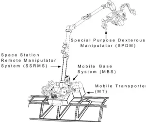
The first step to do when comes the time to study the human factors in a human-machine system is to realise a task analysis of the current situation. Apart from the ROTEX experiment [1] and many rover missions, the operation of space manipulators has been limited to the use of the Shuttle Remote Manipulator System (SRMS, also known as Canadarm), and since this year, the Space Station Remote Manipulator System (SSRMS, also known as Canadarm2). The later is the first element of the Mobile Servicing System (MSS), which is the Canadian contribution to the ISS (see Figure 1).
Figure 1. The Mobile Servicing System (MSS) The SSRMS will later be joined by the two other elements of the MSS, called the Mobile Base System (MBS) and the Special Purpose Dexterous Manipulator (SPDM). Finally, two other manipulators, the European Robotic Arm (ERA) and the Japanese Experiment Module Remote Manipulator System (JEMRMS) will eventually join the ISS. Our task analysis focuses on the two currently operational space telemanipulators that are the SRMS and SSRMS. We present here the first results of the ongoing task analysis.
2.1.1 Systems Overview
The SRMS is a 15.2 m long, 6 dof arm controlled by 6 rotational joints (Figure 2). It is fixed at one extremity into the shuttle bay and is equipped with a latching end effector (LEE) that is used mainly to grapple payloads. The SRMS can be equipped with two video cameras. One is fixed at the wrist joint while the other is optional and is mounted on a pan/tilt unit (PTU) at the elbow joint. The SRMS can handle payloads of up to 30 metric tons, moving at a speed of 6 cm/s, and move up to a speed of 60 cm/s when unloaded.
Figure 2. The SRMS (Canadarm)
The SSRMS (Figure 3) is similar to the SRMS but is 17.6 m long, has 7 dofs and is a symmetrical arm (i.e. that the “shoulder” can become a “wrist”). This configuration allows the SSRMS to change its mounting point and displace itself on the ISS by moving end-over-end in an inchworm-like movement. For this reason, it is equipped with two latching end effectors, one at each extremity.
This arm is more powerful than its predecessor and can handle payloads of up to 116 metric tons (i.e. the equivalent of the space shuttle) at a speed of 1.2 cm/s, up to a speed of 37 cm/s when it is unloaded. The SSRMS is equipped with four cameras, one fixed at each end and two others mounted on the arm near the elbow, on pan/tilt units.
Figure 3. The SSRMS (Canadarm2)
Once the whole MSS is in place, the SSRMS will also be able to be mounted on the MBS, which itself is mounted on the Mobile Transporter (MT) that moves along the ISS truss rails. Finally, the MT/MBS will be used to transport the SSRMS, the SPDM and the payloads along the truss, between the ten designated worksites, at a maximum speed of 2.5 cm/s [2].
2.1.2 Control Interfaces
Although slightly different, the control interfaces of the SRMS and the SSRMS both uses the same two 3-dof joysticks, for a total of 6 dofs controlling the position and rotation of the manipulators. The control interfaces both use rate control and can be operated in different modes. The human-in-the-loop control modes are:
Single Joint Mode: The operator moves the arm by
controlling only one joint at a time.
Manual Augmented Mode: In this mode, also called
coordinated or resolved mode, the operator control the translation and rotation of a particular Point of Reference (POR) on the arm, usually located at the tip of the end effector. The translation are done along a cartesian axis while the rotation are done along the yaw-pitch-roll axis.
Arm Pitch Plane Mode: This mode is available only on
the SRRMS because of its particular geometry and the presence of a seventh dof. It allows the operator to rotate the “elbow” around the axis defined by the wrist pitch and shoulder pitch reference frame. In this way, the operator can move the arm in a position that avoids collision with an eventual obstacle, without the need to reposition the end effector, which keeps the same position and orientation during the movement of the rest of the arm.
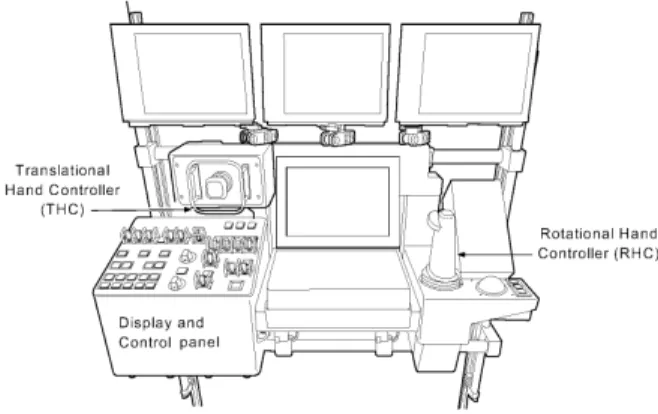
The operator can look at the operations either directly through a window or through video cameras displayed on the video monitors. Figure 4 illustrates the SSRMS control interface, called Robotic Workstation (RWS).
Figure 4. The Robotic Work Station (RWS) Two RWS will be available on the ISS, one located in the U.S. Lab Destiny and the other in the Cupola. During operations, one RWS is active, while the other is in monitor mode or powered down. The active RWS has primary control of MSS functions, while the backup provides only the emergency stop, the control/display of additional cameras views, and feedback of function status [2]. The RWS are equipped with 3 video monitors that can show the output of three
selectable cameras. The display and control panel is used for the selection of the cameras and the control of their pan/tilt units when they are available. The operator can also control the focus and the zoom of the cameras.
2.1.3 Main Tasks
These SRMS and SSRMS are used mainly for payload handling, EVA support and ISS assembly. The SSRMS will also be used for the service and maintenance of the ISS, the transport of payloads on the MT/MBS (with a maximum load of 5000 kg), as well as for the berthing/de-berthing of the Orbiter. It is common for a task to take of several hours to be completed.
For the loading and unloading of the Orbiter cargo bay, the two arms can be used, either alone or together in a hand-off manoeuvre. In the latter case, the SRMS is used to un-berth the payload from the cargo bay and position it in free space in a position that allows the SSRMS to grapple the payload. The SSRMS then moves the payload to its final position or onto the MT/MBS for transportation. Loading payloads in the Orbiter cargo bay can be done in the reverse order.
For the capture the Orbiter, the SSRMS has to step off from the MBS to a position on the Lab module PDGF (Power Data Grapple Fixture). As the Orbiter slowly (at a maximum speed of about 3cm/s in any direction) approaches the capture box (a cube with sides measuring about 5 m), the SSRMS begins to track the grapple fixture on the Orbiter bay. The operator then commands the SSRMS LEE to approach and capture the Orbiter, under manual or auto control [3].
2.1.4 Operators
Since the operation of the manipulators is done in space, all the operators are astronauts/cosmonauts (i.e. highly skilled, highly trained individuals). For the control of the manipulators they follow procedures that have been previously repeated on simulators.
Generally, two operators are used to control the manipulators. The first uses the controls, while the other is monitoring the activities.
The training for the SRMS is provided by the NASA at the Johnson Space Center (JSC) in Houston, while the training for the SSRMS is provided by the Canadian Space Agency (CSA) at the John H. Chapman Space Centre in St-Hubert.
The hands-on training for the SRMS is done both on physical and virtual simulators, while only virtual simulation is used for the SSRMS.
2.2 Preliminary Results
The analysis of current space telemanipulation activities, such as those realized by the SRMS for the assembly of the International Space Station (ISS), reveals that in many circumstances the use of video cameras for the visualization of the work site is not optimal in terms of coverage of the worksite, as well as in usability. A good example of this occurred during the ISS assembly mission 5A (shuttle mission STS-98). The operator of the SRMS had to be helped by two other crew members in Extra-Vehicular Activities (EVA) during the installation of the Destiny module, in order to avoid collision with objects in the environment. The two astronauts served as guides for the SRMS operator that could not see well enough to insure collision avoidance [4]. We think similar situations are likely to occur during SSRMS operations. Using models of the objects that are in space, virtual reality technology can improve the visualization of the work site, by providing the operator, on demand, unlimited, global and local views of the worksite, adjusted to his/her needs. This contrasts sharply with the limited set of observations points provided by video cameras and windows.
Furthermore, the use of models of the environment allows for improved security of operations, by using collision avoidance systems [5]. Finally, such a system can also benefit from informations coming from the Artifical Vision Unit (AVU) [6, 7].
In fact, this system could become a superset of the current human-machine interface used to operate space manipulators. It would therefore allows to replicate the current interfaces with the possibility to expand their functionalities and capacities well beyond their current states.
Such a system will also allows for the exploration and the experimental comparison of different ways to present the information about the environment, as well as different ways to control it through this new kind of human-machine interface. Many challenges such as navigation methods to select the point of view, to the selection methods used to switch between command modes must be taken care of to further improve the overall human-machine performance and safety of the space telemanipulation systems. We think that the use of direct manipulation interfaces has the potential to improve current interfaces.
We therefore presents an overview of the design of such a system that will be developed in the ROSA project to demonstrate the potential of virtualized reality to tackle these issues.
3 VR System Overview
Telepresence is generally defined as the art of enabling cognitive proximity despite geographical distances. In this research we would like to explicitly address the problem of remote site exploration and operational control. The objective is therefore to provide to an observer a vivid experience in which he will have the possibility to interactively visit and remotely explore an existing remote environment.
Currently, most Tele-presence systems use one of the following two approaches: the first approach is based on the use of multiple cameras, often-panoramic cameras, in order to obtain a large visual coverage of the site. Video sequences are then sent to the user, giving him a live access to the site. However, the exploration of the world is, in this case, strongly limited by the available viewpoints and by the bandwidth of the communication channel. The other solution consists in the prior acquisition of a 3D model of the site that can be used by a virtualized reality system during the telepresence experience. Unrestricted real-time navigation across the virtualized environment becomes then possible, but since no direct link with the remote site is present, the observed model does not always reflect the current reality.
Although these solutions are of interest, we believe that in order to provide the user with a realistic immersive telepresence experience, the system must offer both at the same time; real-time unrestricted navigation and live information that reflect the current site conditions. The originality of the approach we proposed is that it stands in between the two current solutions described above. Our system will use a 3D model of the remote site (allowing real-time unrestricted navigation) but the appearance of this 3D model will be regularly refreshed using information obtained from a set of cameras and sensors strategically located at the remote site thus allowing for live visualization.
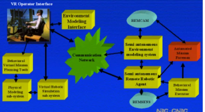
The proposed system (Figure 5) is composed of four main sub-systems:
• A modelling station
• A VR based operator/ observer station • A data communication controller
• An on board remote monitoring sensing system Each sub-system is connected via a communication infrastructure that must be able to deal with various levels of connection quality and speed over great distances. To achieve this over any distributed system node, whether it is remote equipment, an operator
station, or an observer station, the system must be capable of receiving data communications from any other system node in as timely a manner as possible. Additionally, given the bandwidth and latency limitations of data communication links over large distances, the system must address the time differences that are inevitable between physical events and the corresponding received data.
Figure 5. VR Monitoring Environment The current implementation of our system employs in-house server software using socket communication between the sensing elements and a central server residing on a dedicated PC. In the new implementation, we plan to use CAVERNSoft [8] from the Electronic Visualization Laboratory at the University of Illinois to form this communication backbone.
The basic idea behind CAVERNSoft consists of activating an IRB (Information Request Broker) on every computer in the system, therefore creating a virtual private network amongst them. Using this software, the interconnection of data communications between network nodes and the sharing of data that is of interest to several nodes is made transparent to the application software. In CAVERNSoft there is also a notion of Quality of Service (QoS). Using this notion of QoS, CAVERNSoft is able to perform various physical connections on the same data channel and is capable of switching automatically from one physical connection to an other if the QoS of the current connection degrades. This is an essential feature for any space application, where the quality of the communication can vary widely.
Using CAVERNSoft, the system interconnections are open and scaleable to any number of network node entities. Furthermore, the actual physical layer of the communications network is left open. Data formats for the system are also open and determined by the producers of data.
4 Operator/Observer Station
From its workstation, the user will use NRC 3D visualization software to navigate in real time inside the remote site by specifying virtual displacements. The system will then present to the user images of the site, as seen from the specified viewpoints, appearing in a state corresponding to the current existing conditions. One of the main challenges will be to adapt NRC technology to the context where the 3D structure of the model and its visual appearance are completely de-coupled. The incorporation of dynamic elements without predefined behaviours is also a challenging aspect in the context of these technologies where the behaviours of the dynamic elements is normally part of the programming constructs of the virtual model. More generally, the problem of keeping a 3D virtualized model coherent with its real counterpart as perceived by a set of cameras and range sensors is a relatively new concept that will require innovative solutions. Using the system the operator will also have the ability to program and rehearse, in real-time inside the virtual world, the various operations that need to be performed. The operator will be able to program the robot using various methods based for example on behavioural programming, direct manipulation or simple joint control. Using physical simulation, the operator will also be able to rehearse the operation and make corrections before the final work plan is transmitted to the real robot. Using this approach, an operator will be able to specify long sequencea of robot movements and if the physical simulation is accurate, he will be able to predict the outcome of his programming. At the local robotic station these operational plans are received and executed. At the local site, an automated mission foreman will compare in real time the predicted operation and the real one. If there is any discrepancies between them, the local robot will transmit a report of these variations to the operator. Using this report, the operators will then be able, with the help of analysis tools, to determine the cause of this discrepancy and make corrections to the physical simulation parameters and to the virtual 3-D model that reflects these changes.
5 Modeling Station for Dynamic
Model Update
In this system, visual information is extracted from images received from cameras located at the remote site. A transmission link between the on-site cameras and the local workstation(s) must therefore be established. In this case, a simple TCP/IP connection
can be set, which has the important advantage that all interactions between cameras and local 3D models will transit through the best communication channel. This is a strong limitation, especially in space, where the communications link are limited both in terms of transmission rate and reliability, not to talk about time delays that are commonly greater than eight seconds. This is particularly true in our situation because the application involves multiple sources of sensor and video transmission that is usually very demanding in terms of transmission bandwidth. However, because of the existence of the 3D model, the rate at which the visual information must be refreshed can be kept very low. New images can be transmitted only when significant changes occur in the scene and when these changes will affect the currently observed portion of the 3D model. Selective transmission of image elements will therefore be investigated.
The different sources of visual information will also be used to infer the required 3D information about the scene under observation. Indeed, effective virtual navigation across the remote site relies on the use of a 3D model of the static elements of the scene. Inferring 3D structure from multiple views is a very challenging problem, of great practical interest, that has not yet been solved in the general case. For this reason, model building constitutes one of the most active areas of research in the computer vision community. However, since in the present application the construction of the 3D model can be performed offline, human guidance can be used. This poses the problem of 3D estimation, which is to determine the kind of information a user must provide, and the way this information can be used in order to obtain reliable 3D estimates. The research will therefore have to devise new procedures for the estimation of 3D structure, camera poses, and cameras intrinsic parameters. One can refer to the large body of work in this field for more detailed information [9, 10]. The correct registration between the 3D models and each camera view is also a central aspect. This is achieved by keeping the camera images accurately aligned with the 3D model. This way the appearance of this 3D model will always reflect the existing conditions that currently prevail at the remote site. In the context of the proposed research, correct registration will have to be constantly re-estimated in order to prevent unavoidable deviation due to small camera motions. In addition, when several cameras will share common points of view, methods to combine these redundant sources of information have to be devised. Finally, in order to increase the live sensation, the dynamic elements of the site will be incorporated to the image sequence. These moving elements will be identified by comparing the available views and will
thus be correctly positioned on the 3D model before display.
In order to create this live dynamic model of a real environment one must first create a 3D model of the basic elements. Such elements may includes the know terrain around a mars rover or the current configuration of infrastructures around the work area such as the space station as well as dynamic objects populating this environment such as robotic arms and satellites. Many techniques are used to create such models but most of these models must follow some basic criteria:
• The model must be accurate
• The model must be easily interpreted
• The model must be compatible with VR display systems
• Each model should have various levels of detail The most common representation of a VR model is by the use of a scene graph technique [11]. Contrary to a pure geometrical representation where no optimization is possible, a scene graph can be optimized to hide various latencies of the display and communication system. This is because a scene graph is a structured representation of the various relationships between elements of a scene. A scene graph allows for easy propagation of properties along the hierarchy, as well as allows the notion of level of details and context switching.
One of the most important and fundamental problems in VR modelling is the selection of the right level of detail (LOD). This requirement comes from a fundamental compromise between display speed and model complexity. By using a well designed scene graph one can hide various latencies such as display speed and communication load using techniques such as geometric and communication LOD and graph culling. This is an important consideration since a complete space station model can be extremely large.
6 Discussion
This project requires the combined use of three important fields of information technologies, namely, telecommunications, visual information processing and computing technology. The research will therefore have to integrate these technologies and therefore, will contribute to develop the knowledge in this important area of research. The convergence of computer vision with virtual reality is now an emerging trend and the research done in this project should contribute to pioneer the investigation in this domain. A substantial
benefit of the judicious integration of these technologies results in the possibility to use the system under a low bandwidth network, a fact-of-life in space applications.
7 Acknowledgments
This work described in this paper is part of an ongoing collaborative research project between the company MD Robotics, The National Research Council of Canada and the Canadian Space Agency. This project is made possible thanks to the partial funding of PRECARN.
References
[1] Hirzinger, G., Brunner, B., Dietrich, J., Heindl, J., “ROTEX: The First Remotely Controlled Robot in Space”, Proc. of ICRA 94, the IEEE International Conference on Robotics and Automation, Vol. 3, 1994, pp.2604-2611.
[2] NASA, “International Space Station Familiarization”, ISS FAM C 21109, July 31, 1998. http://www.spaceflight.nasa.gov
[3] MD Robotics, “SSRMS Operating Procedures”, SPAR-SS-PR-2362, Issue A.
[4] Lozano, J., “Les astronautes d’Atlantis installent Destiny sur la SSI”, La Presse, February 11, 2001, page A7.
[5] Greenspan, M., Burtnyk, N., “Obstacle Count Independent Real-Time Collision Avoidance”, Proceedings of ICRA 96, the International Conference on Robotics and Automation, Vol. 2, 1996, pp.1073-1080.
[6] MacLean, S.G., Rioux, M., Blais, F., Grodski, J., Milgram, P., Pinkney, H.F.L., Aikenhead, B.A., “Vision System Development in a Space Simulation Laboratory”. Proceedings.of
Commission V Symposium, ISPRS, “Close-Range Photogrammetry Meets Machine Vision”, 1990, pp.8-15.
[7] Pinkney H.F.L., MacLean, S.G., “Machine Vision in Space”, Canadian Aeronautics and Space Journal, Vol. 39, No. 2, June 1993, pp.63-77.
[8] Leigh, J., Johnson, A. E., DeFanti, T.A., CAVERN: A Distributed Architecture for Supporting Scalable Persistence and Interoperability in Collaborative Virtual Environments in Journal of Virtual Reality Research, Development and Applications, Vol 2.2, December 1997 (1996), Pp 217-237, the Virtual Reality Society, 1997.
[9] Brown D.C., “The bundle adjustment- progress and prospective “, International Archives of Photogrammetry, No 3-03-041, 33 pages, ISP Congress, Helsinki, Findland, 1976.
[10] El-Hakim, S.F., Brenner C., and Roth G., “ A multi-sensor approach to creating accurate virtual environment”, ISPRS Journal of Photrgrammetry and Remote Sensing, Vol. 53, 1998, pp. 379-391. [11] Wernecke, J., “The Inventor Mentor”,
Addison-Wesley Publishing Company, ISBN 0-201-62495-9, 1994.