Publisher’s version / Version de l'éditeur:
Vous avez des questions? Nous pouvons vous aider. Pour communiquer directement avec un auteur, consultez la première page de la revue dans laquelle son article a été publié afin de trouver ses coordonnées. Si vous n’arrivez pas à les repérer, communiquez avec nous à PublicationsArchive-ArchivesPublications@nrc-cnrc.gc.ca.
Questions? Contact the NRC Publications Archive team at
PublicationsArchive-ArchivesPublications@nrc-cnrc.gc.ca. If you wish to email the authors directly, please see the first page of the publication for their contact information.
https://publications-cnrc.canada.ca/fra/droits
L’accès à ce site Web et l’utilisation de son contenu sont assujettis aux conditions présentées dans le site LISEZ CES CONDITIONS ATTENTIVEMENT AVANT D’UTILISER CE SITE WEB.
IOP Conference Series: Materials Science and Engineering, 418, 2018-09-01
READ THESE TERMS AND CONDITIONS CAREFULLY BEFORE USING THIS WEBSITE.
https://nrc-publications.canada.ca/eng/copyright
NRC Publications Archive Record / Notice des Archives des publications du CNRC : https://nrc-publications.canada.ca/eng/view/object/?id=2c19b6f5-8bfa-40da-9aa0-314a19f5eea3 https://publications-cnrc.canada.ca/fra/voir/objet/?id=2c19b6f5-8bfa-40da-9aa0-314a19f5eea3
NRC Publications Archive
Archives des publications du CNRC
This publication could be one of several versions: author’s original, accepted manuscript or the publisher’s version. / La version de cette publication peut être l’une des suivantes : la version prépublication de l’auteur, la version acceptée du manuscrit ou la version de l’éditeur.
For the publisher’s version, please access the DOI link below./ Pour consulter la version de l’éditeur, utilisez le lien DOI ci-dessous.
https://doi.org/10.1088/1757-899X/418/1/012034
Access and use of this website and the material on it are subject to the Terms and Conditions set forth at
High temperature characterization and material model calibration for
hot stamping of AA7075 aluminium sheet
IOP Conference Series: Materials Science and Engineering
PAPER • OPEN ACCESS
High temperature characterization and material model calibration for hot
stamping of AA7075 aluminium sheet
To cite this article: G D’ Amours and A Ilinich 2018 IOP Conf. Ser.: Mater. Sci. Eng. 418 012034
View the article online for updates and enhancements.
1
Content from this work may be used under the terms of theCreative Commons Attribution 3.0 licence. Any further distribution of this work must maintain attribution to the author(s) and the title of the work, journal citation and DOI.
Published under licence by IOP Publishing Ltd
1234567890‘’“”
International Deep Drawing Research Group 37th Annual Conference IOP Publishing IOP Conf. Series: Materials Science and Engineering 418 (2018) 012034 doi:10.1088/1757-899X/418/1/012034
High temperature characterization and material model
calibration for hot stamping of AA7075 aluminium sheet
G D’Amours1 and A Ilinich2
1 National Research Council Canada, Aluminium Technology Centre, Saguenay,
Québec, Canada
2 Ford Research and Innovation Center, Dearborn, Michigan, USA
Guillaume.Damours@cnrc-nrc.gc.ca, ailinich@ford.com
Abstract. This paper presents an overview of the elevated temperature characterization of
AA7075 aluminium sheet and calibration of a custom material model implemented in LS-DYNA. The plasticity characterization was performed by isothermal tensile testing while formability characterization was performed via isothermal Nakazima testing in a wide range of temperatures and strain rates. A special heat treatment path representative of the hot stamping was developed and applied in both series of tests. The material model included Hill’48 yield with a non-associated flow rule and phenomenological damage model similar to GISSMO but extended to cover non-isothermal conditions.
1. Introduction
Auto manufacturers can improve fuel economy by decreasing the weight of their vehicles. The high strength AA7075 aluminium sheet is an attractive lightweight material for automotive applications due to high specific strength in T6 or T7x tempers. However, its usage is still very limited partially due to poor room temperature formability. Elevating temperature of the sheet prior to forming is a possible solution to this problem as it leads to an increase in material ductility and a decrease in flow stress. In hot forming, the sheet is solutionized (i.e. heated above the solvus temperature) before the stamping operation. The process is carried out in non-isothermal conditions where die is cooled to almost room temperature. In recent years, some researchers such as Harrison et al. [1], Ilinich et al. [2], Xiao et al. [3] and Kumar et al. [4] investigated this process and formed prototype parts with AA7XXX aluminium alloys.
Plasticity characterization for finite element analysis is typically performed via isothermal uniaxial tensile tests covering the expected range of temperatures and strain rates. Formability characterization may be performed via a set of isothermal Nakazima tests covering the expected range of temperatures, strain rates and loading paths. Modeling elevated temperature forming is more complicated than modeling conventional stamping. The finite element software LS-DYNA has some plane stress material models applicable for non-isothermal forming. However, there are no general stress state models available for solid elements that can describe aluminium anisotropy and support temperature and rate dependant hardening. For damage, LS-DYNA has a phenomenological damage accumulation model capable to predict both plastic instability and fracture. However, its current implementation is limited to isothermal conditions. Therefore, new models are necessary for the finite element analysis of the aluminium hot stamping process that take into account evolution of anisotropy, strain hardening and damage of aluminium sheet due to large temperature, strain rate, and loading path variations observed
2 1234567890‘’“”
International Deep Drawing Research Group 37th Annual Conference IOP Publishing IOP Conf. Series: Materials Science and Engineering 418 (2018) 012034 doi:10.1088/1757-899X/418/1/012034
during hot forming. This paper presents an overview of the material characterization, the development and validation of a plasticity model coupled with a phenomenological damage model for aluminium hot stamping.
2. Material of study
The material of study was AA7075 aluminium sheet with thickness of 2 mm and chemical composition shown in Table 1 [1]. The sheet was received in T6 temper.
Table 1. Chemical composition of AA7075 aluminium sheet
Elements Al Cr Cu Fe Mg Mn Si Ti Zn Other, Each Other, total Wt. (%) 87.1-91.4 0.18-0.28 1.2-2.0 Max. 0.5 2.1-2.9 Max. 0.3 Max. 0.4 Max. 0.2 5.1-6.1 Max. 0.05 Max. 0.15
3. Elevated temperature characterization of AA7075 aluminium sheet 3.1. Plasticity characterization
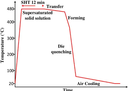
In the AA7075 hot stamping process, heat transfer between the blank and the die causes rapid change in local temperature of the blank which combined with non-uniform strain rate leads to fast evolution of material properties. Therefore, material characterization covering the expected range of temperature and strain rate is critical for accurate modelling. It is equally important to test the material in proper conditions representative of the hot forming process. A typical thermal cycle for AA7075 sheet during the hot stamping process is shown in Figure 1. The material is fully solutionized before forming and is in a solid solution state at the beginning of the forming operation with temperature still above solvus. During the forming and die quench operation, the temperature decreases below solvus and material enters a state of supersaturated solid solution due to the high quench rate.
Time Tem per a tu re (°C ) SHT 12 min 480 Supersaturated solid solution 20 200 100 300 400 Die quenching Transfer Forming Air Cooling
Figure 1. Example of a typical thermal cycle for 7075 sheet during hot stamping.
Isothermal uniaxial tensile test with ASTM E21 specimen geometry was used in this work to obtain mechanical properties at elevated temperatures. The samples were machined in three directions with respect to the rolling direction: longitudinal, diagonal, and transverse. The tests were carried out over a temperature range of 200 to 480 °C and strain rates from 0.01 to 10 s-1. The true stress and strain were
calculated from the load force and crosshead displacement up to the uniform elongation. A Pyradia radiation furnace was used for the solution heat treatment of all the uniaxial samples. Salt bath quenching was performed in a Lindberg furnace using a cylindrical crucible. The temperature of the salt bath was
3 1234567890‘’“”
International Deep Drawing Research Group 37th Annual Conference IOP Publishing IOP Conf. Series: Materials Science and Engineering 418 (2018) 012034 doi:10.1088/1757-899X/418/1/012034
set up to 30 °C higher than the target temperature of the test to compensate for the heat loss during the subsequent sample transfer and mounting. After quenching, the samples were transferred in 4 s to an environmental chamber (MTS-651) set at the target test temperature and tested on a MTS hydraulic tensile machine 810. The resultant thermal cycles, schematically shown in Figure 2, closely replicated the thermo-mechanical history of a typical hot stamping process.
Time T em p e r at u r e ( °C ) SHT 12 min 480 Salt bath quench Supersaturated solid solution High temperature tensile tests 20 200 100 300 400 500 X X X X X X
Figure 2. Heat-treat paths and equipment used for hot tensile tests.
The Lankford coefficients (R-values) were measured in three directions over the same temperature range using interrupted tensile tests as no technique was available for in-test transverse strain measurement. Since material anisotropy is generally unaffected by strain rate, the tests were performed at a single 0.1 s-1 strain rate. The tests were interrupted at different values of strain before necking1 for
every experimental condition. The post-test width and thickness were measured by CMM in the middle of the gage section. The instantaneous R value at this strain level was then calculated as:
,T,ε= ln / ln �� (1)
where and are the initial and final width, � and � are the initial and final thickness. Final R value for given direction and temperature was obtained by averaging values for individual strains ̅ ,T =
∑ �εn ,T,ε
� . Figure 3 gives an example of obtained stress-strain curves and R-values for one temperature
(400 °C). As can be seen in the Figure 3, 7075 alloy at this temperature has substantial plastic flow anisotropy but insignificant stress anisotropy. Similar behavior was observed at other tested temperatures. Another observation is the lack of hardening at lower strain rates which to some extent may have been an artifact of early diffuse necking observed at these rates and the indirect strain measurements.
3.2. Formability characterization
Forming limit diagrams were obtained by isothermal limiting dome height (LDH) testing, also called Nakazima test, with a 101.6 mm hemispherical punch over a range of temperatures and strain rates similar to those used in tensile testing. The testing was performed with graphite lubricant. Three loading paths were included in this study: uniaxial, plane strain and equibiaxial. Specimen geometries were optimized by finite element analysis (FEA). FEA was also used to determine punch displacement profiles for maintaining constant strain rates in the target areas of the blank. The same heat treatment
1
Small diffuse necking (∆ < . 5 ��) was acceptable for experiments where diffuse neck initiated early in the test.
4 1234567890‘’“”
International Deep Drawing Research Group 37th Annual Conference IOP Publishing IOP Conf. Series: Materials Science and Engineering 418 (2018) 012034 doi:10.1088/1757-899X/418/1/012034
path representative of the production hot stamping process and shown in Figure 2 was used to evaluate forming limits. Figure 4 (a) shows the experimental setup, and Figure 4 (b) and (c) show formed biaxial and plane strain samples.
Figure 3. Example of hot tensile tests results.
Due to the lack of means for direct in-test surface strain measurement, the limit strains were determined post-test using a new procedure based on the ISO 12004-2. In this procedure, the through thickness limit strain was determined by ISO 12004-2 parabolic fit to CMM thickness measurements across the neck. The minor in-plane strain was determined by analyzing the grid etched in the sample surface. The major in-plane limit strain was then computed using volume conservation. CMM was also used to determine final fracture thicknesses which were subsequently utilized to calibrate fracture surfaces.
Figure 4. (a) - Nakazima test equipment, (b) biaxial samples after the test, (c) plane strain samples after the test.
An example of thickness measurements is shown in Figure 5 and Figure 6 shows an example of forming limit data for 400 °C. A large variation of forming limit strain depending on the strain rate and strain path can be observed in the Figure 6.
(a) (b)
5 1234567890‘’“”
International Deep Drawing Research Group 37th Annual Conference IOP Publishing IOP Conf. Series: Materials Science and Engineering 418 (2018) 012034 doi:10.1088/1757-899X/418/1/012034
Figure 5. Hot tensile sample at left (T=400°C and �̇=0.1 s-1) and hot plane strain Nakazima at right (T=280°C and �̇=0.1 s-1).
Figure 6. Forming limit diagram for AA7075 at 400 °C.
4. Plasticity and damage modeling of AA7075 aluminium sheet for hot stamping 4.1. Plasticity modeling
One of the goals of the presented work was to create a general plasticity model applicable to both plane stress and 3D elements and able to accurately describe the observed anisotropic behavior as a function of temperature and strain rate. All these requirements can be satisfied by using a non-associated plastic flow rule (non-AFR) which has been used by D’Amours [5] to model plasticity of cohesive, porous and granular materials of aluminium reduction cells. In this model the plastic potential Q and the yield surface F are defined by two separate functions. Stoughton and Yoon [6] discussed potential advantage of non-AFR models for metals as well as stability conditions for unique and positively-definite plastic work. The non-AFR models with simple Q and F functions are in many cases less computationally expensive than more complex AFR models yet capture complex anisotropic behavior equally well or better. These models can be calibrated with just tensile tests and are suitable for both shell and 3D solid elements. Non-AFR models have been recently added in LS-DYNA [7].
Hill 1948 yield function [8] was adopted in the present study for both the plastic potential function Q and the yield surface function F. The yield surface F for 3D solid elements was of the following form:
6 1234567890‘’“”
International Deep Drawing Research Group 37th Annual Conference IOP Publishing IOP Conf. Series: Materials Science and Engineering 418 (2018) 012034 doi:10.1088/1757-899X/418/1/012034
where � are components of the stress tensor in principal orthotropic axes, , , , , and
are free parameters. To include planar stress anisotropy, the stress anisotropy parameters � , �̇ ,
� , �̇ and �9 , �̇ were used according to Wang et al. [9] to determine , , , , and
parameters. At the same time, a plastic potential Q was defined by the same equation but with different parameters to predict the direction of plastic flow increments:
= � − � + � − � + � − � + � + � + � − (3)
To include planar strain anisotropy, R-value parameters , and 9 were used
according to Kami et al. [10] to determine , , , , and parameters of the plastic potential. Examples of plane stress and 3D yield surfaces and plastic potentials for the AA7075 at 400°C are shown in Figure 7. The yield surface shape was closer to von Mises due to lower stress anisotropy. 3D tables were used in the UMAT to include stress-strain curves in the rolling direction and stress anisotropic parameters as functions of temperature and strain rate; and 2D tables were used for R-value functions of temperature. The hardening was assumed isotropic.
Figure 7. Plane stress and 3D yield surfaces and plastic potentials for the AA7075 at 400 °C.
4.2. Damage modeling
Results of the tensile tests and formability characterization revealed complex non-linear influence of temperature and strain rate on plastic instability (necking) and fracture strains. A phenomenological damage accumulation framework was adopted in this study to predict both phenomena. A model similar to GISSMO [11] but with temperature and rate sensitivity was developed and included in the user material subroutine. As in GISSMO, two elemental scalar variables, D and IM, were introduced for fracture and instability risk accumulation respectively at every integration point. Both variables had critical value of 1 and initial value of 1x10⁻¹⁰. An increment of D was computed at every time step upon
completion of plastic update using the following equation: ∆� = ��
� �,�̇,�,�
− ∆��
� �,�̇,�,� (4)
where � and ∆� are the equivalent plastic strain and its increment, is the damage exponent, � is the fracture strain that depends of the temperature T, the strain rate �̇, the stress triaxiality η and the Lode parameter ξ. The instability measure IM, was incremented using:
∆
=
���i�,�̇
− ∆��
�i�,�̇
(5)
where � is the instability strain that depends of the temperature T, the strain rate �̇.
Stress coupling was implemented for the post-instability response (IM ≥ 1) to insure a gradual decrease of load bearing capacity to 0 when the value of damage parameter D reaches unity. This was achieved by the following update to the uncoupled stress vector �⃗:
7 1234567890‘’“”
International Deep Drawing Research Group 37th Annual Conference IOP Publishing IOP Conf. Series: Materials Science and Engineering 418 (2018) 012034 doi:10.1088/1757-899X/418/1/012034
�⃗ = ( − �n w−�ins −�ins
�
) �⃗ (6) where � is the fade exponent for stress coupling and Dins is the value of D when the instability IM reaches the value of 1.0. The instability strain � , �̇ was determined directly from the hot tensile test results. Fracture surfaces � �, � were assumed to have shape proposed by Bai et al. [12]:
� = ξs+ −√√ ( ξa − ξs s ��6 − (√ + cos �� + � + sin �� )) −�
(7)
ξa= {
ξ��� � ≥
��� � <
(8)
where ξs , �̇ , c0 , �̇ , c1 , �̇ , ξ , �̇ , and n , �̇ are free parameters determined separately for each combination of temperature and strain rate by minimizing the difference between the experimental and simulation results for three loading paths (uniaxial, plane strain and biaxial).
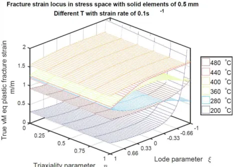
Since the fracture strain is mesh size, element formulation and implicit time step dependent, these parameters were kept constant in all calibration and validation models. The nonlinearity of the experimental strain paths was automatically accounted for by using damage accumulation in the model. Therefore, � was also depended on and � parameters. Figure 8 presents fracture surfaces obtained for different temperatures at the strain rate of 0.1 s-1. Interestingly, the maximum fracture strain was
observed at 400°C as opposed to 480°C.
Figure8.Fracturestrainsurfacesidentifiedfor six temperatures and the strain rate of0.1s-1.
5. Validation
Aluminium hot stamping trials with AA7075 have been executedusingdifferentexperimental setups. Most ofthe experiments have been modeled with both shell and solid elementsin order to validate the modelfor bothelementformulations.Overall, both types of models demonstratedreasonable accuracy in predicting strain distribution and thickness. The models were also able to predict plastic instability and fracture.Figure 9 shows an example of a biaxial Nakazimasample hot stamped close to fracture with a largevisibleneckandthecorresponding distributionof the damage parameterDpredicted by the solid element model.
8 1234567890‘’“”
International Deep Drawing Research Group 37th Annual Conference IOP Publishing IOP Conf. Series: Materials Science and Engineering 418 (2018) 012034 doi:10.1088/1757-899X/418/1/012034
Figure 9.Hot stamped biaxial samplewithlargevisible neck andpredicteddamagedistribution.
6. Conclusion
This paper presented an overview of the elevated temperature characterization of AA7075 aluminium sheetthat is necessaryfor proper hot stamping process simulation usingadvanced plasticity and damage models. A custom material model was developed and implemented in LS-DYNA to overcome shortcomings of the existing models.The non-associated flow rule was selected foraccurate anisotropy description. For damage and fracture treatment, a phenomenological temperature and strain rate sensitivedamage accumulation model was implemented in this study. This approach demonstrated great potential in predicting both the plastic instability and fracture in hot forming.
References
[1] Harrison N R and Luckey S G 2014. Hot stamping of a B-pillar outer from high strength aluminum sheet AA7075 SAE Int. J. Mater. Manuf. 7 pp 567–73
[2] Ilinich A and Luckey S G 2014 On Modeling the hot stamping of high strength aluminum sheet
SAE Int.
[3] Xiao W, Wang B and Zheng K 2017. An experimental and numerical investigation on the formability of AA7075 sheet in hot stamping condition Int. J. Adv. Manuf. Tech. 92 pp 3299– 09
[4] Kumar M and Ross N G 2017. Investigations on the hot stamping of AW-7921-T4 alloy sheet
Adv. Mater. Sci. Eng. pp 1–10
[5] D’Amours G 2004 Développement de Lois Constitutives Thermomécaniques pour les Matériaux
à Base de Carbone lors du Préchauffage d’une cuve d’électrolyse Université Laval Québec
[6] Stoughton T B and Yoon J W 2011 Paradigm change : alternate approaches to constitutive and necking models for sheet metal forming AIP conference proceedingS 1383 pp 15-34
[7] 2018 LS-DYNA Keyword User’s Manual II LSTC Livermore
[8] Hill R 1948 A Theory of the yielding and plastic flow of anisotropic metals Math. Phys. Eng. Sci.
193 pp 281–97
[9] Wang G, Qian X, Li X, Hou H, Liu Y and Lou Y 2014 A study on compressive anisotropy and nonassociated flow plasticity of the AZ31 magnesium alloy in hot rolling Mathematical
Problems in Engineering 2014 pp 1–9
[10] Kami A, Bijan M D, Seyed ali S V, Dan-Sorin C and Banabic D 2014 Application of a GTN damage model to predict the fracture of metallic sheets subjected to deep-drawing. P.
Romanian Acad. 15 pp 300-9
[11] Andrade F X C, Feucht M, Haufe A and Neukamm F 2016 An incremental stress state dependent damage model for ductile failure prediction Int. J. Fract. 200 pp 127–50
[12] Bai Y and Wierzbicki T 2009 Application of extended Mohr–Coulomb criterion to ductile fracture Int. J. Fract. 161 pp.1–20