PFC/RR-82-31 DOE/ET-51013-60 UC20
ANNUAL TECINICAL REPORT Editors: T. F. Yang P. Gierszewski Contributors: D. T. Blackfield (MIT) D. A. Bowers (McDonnell) F. R. Chang (NASA) E. T. C. Cheng (GA) J. W. H. Chi (Westinghouse) R. B. Chianese (Westinghouse) J. W. Davis (McDonnell) M. J. Delaney (McDonnell) J. R. Easoz (Westinghouse) J. L. Fisher (Draper) P. Gierszewski (MIT) R. E. Gold (Westinghouse) G. R. Hopkins (GA) E. M. Iwinski (Westinghouse) D. Klein (Westinghouse) J. McMurray (MIT/Army) B. Mikic (MIT) D. B. Montgomergy (MIT) J. D. Morgan (McDonnell) M. D. Nahemow (Westinghouse) R. Potok (MIT) E. J. Rapperport (MIT) D. E. Ruester (McDonnell) P. B. Stones (McDonnell) C. R. Taylor (Westinghouse) P. Theriault (Georgia Tech) N. Todreas (MIT)
J. E. Tracey (MIT) A. Wan (MIT) T. F. Yang (MIT)
December 3, 1982 Plasma Fusion Center
TABLE OF CONTENTS
Acknowledments . . . . . . . .. Overview . . . . . . . . Publications and Presentations . . . . 1.0 Bundle Divertor Design . . . ..
1.1 Optimization and Monte Carlo Modeling of Bundle Divertors . 1.2 A Toroidal Hybrid Divertor - Key Hole Divertor . . . . 1.3 Textor Divertor Design . . . . . . . . . . . 1.4 Applications of Cryogenic Magnets . . . . 2.0 Magnet Shielding . . . . . . . . . . . . 2.1 Divertor Shielding Assessment . . . . 3.0 Divertor Physics . . . . 3.1 Plasma/Neutral Gas Transport in Divertors . . . . 4.0 Power Test of the ISX-B Bundle Divertor . . . .. 5.0 Divertor Target Design . . . .
5.1 Experimental Study of Heavy-Walled Water-Cooled Molybdenu 5.2 Supersonic Gas Target Design . . . . 5.3 Divertor Solid Target Options . . . .. 5.4 Matted Fiber Targets for Sputter Resistance . . . . 6.0 Limiter Design . . . . . 6.1 Actively Cooled Limiters for Alcator A and C . . . . . 6.2 Actively Cooled Limiters for Doublet-IlII . . . . 6.3 Composite Limiters for Ablation Control . . . . . ..
. . . .ii . . . .jj . . . .v . . . . . . . 1 . . . . 1 . . . . 1.22 . . . . 1.29 . . . . 1.36 . . . . . . . . 2.1 .2.1 . . . . 3.1 . . . . 3.1 . . . . 4.1 . . . . 5.1 m Tubing . . . . 5.1 . . . . . . 5.17 . . I . . . . 5.31 . . . . 5.51 . . . . 6.1 . . . . 6.1 . . . . 6.10 . I . . . . 6.16
ACKNOWLEDGMENTS
This work was partially supported by the Department of Energy to develop plasma exhaust systems and high heat load limiters. It was carried out with participation of industries such as General Atomic, Mc Donnell Douglas and Westinghouse. The particle transport in the divertor is a joint effort of MIT and the University of Arizona, under the direction of Professor R. Morse. The supersonic jet target work was partially supported by NASA and is a joint effort of MIT, NASA and Draper Laboratory. The solid target study was partially supported by the Department of Defense. The production of this report was greatly facilitated by the excellent work of Mrs. A. Kotsopoulos.
OVERVIEW
This report is a summary of work performed during 1981-82. The studies and experiments described are focused on the timely development of exhaust and impurity control systems for magnetically confined fusion. Areas investigated include divertor engineering (magnetic fields, thermal-hydraulics, shielding and target design); impurity and plasma transport analyses to assess effectiveness of the designs; and design and tests of high heat flux limiter concepts.
It was found that an optimized cascade T-shaped bundle divertor can be designed to be superconducting and meet the engineering constraints of a power reactor. For example, two-dimensional neutronic studies by General Atomic show that the 60 cm of space available in front of the divertor will provide adequate shielding. Monte Carlo modeling of such a divertor indicated that plasma thermal conductivity is increased only 40% over the neoclassical value for an axisymmetric plasma and that the divertor will enhance outward impurity transport compared with the net inward diffusion of an undiverted axisymmetric tokamak. A long pulse divertor was designed to test these results on TEXTOR, and the possible advantages of cryogenic cooling explored.
A key hole toroidal hybrid divertor concept has also been developed. This is a thin, poloidally elongated bundle divertor that is shaped to the plasma surface. As a result, qg is smaller and the diversion efficiency is higher. Such a divertor can be operated in a pulsed mode in a high-field compact device like Alcator. The divertor is small, inexpensive to build, and disposable.
The bundle divertor developed and built for ISX-B was successfully tested at MIT for electrical, magnetic, and structural characteristics. A heat load measurement on a forced flow, water cooled, heavy-wall molybdenum tube has been carried out by Westinghouse. About 1.2 kW/cm2 was handled without any noticeable damage over many pulses. A 2 kW/cm2
heat load was also tested, but with some local melting due to peak load higher than 2 kW/cm2. A water cooled limiter was
designed by McDonnell Douglas with a 1 mm molybdenum skin on 2 mm copper. From the testing results and computations, it is believed that the limiter can be operated safely at a 2 kW/cm2 heat load in an Alcator plasma. The theoretical advantages of porous surfaces for enhancing redeposition of sputtered material were separately studied and found to reduce sputtering by factors of two.
A kinetic model of plasma/neutral gas transport in a bundle divertor is being developed to provide a better basis for the engineering design of divertor targets, as well as assessing impurity control features. Using present information, a scoping study of divertor solid targets confirmed the advantages of thermally connected, mechanically unbonded designs, and identified key thermal-hydraulic factors and data uncertainties for water cooling up to 2 kW/cm2
was proposed for recovering both energy and particles from a bundle divertor. The concept also has implication for future application in rocket nozzle cooling and thrust control with chemicals on fusion engines.
A novel self-protective blistering process in a composite material C-SiC alloy was proposed and tested by General Atomic. The blistering mechanism may limit the erosion of plasma inter-face components subject to disruptive energy load in tokamaks. Additionally, some C-SiC alloy coatings were tested and did not blister, surviving to the limits of the graphite substrate with only microcracking. Both coatings appear suitable for limiter application. A method and mechanism for testing and developing limiters on Doublet IlIl was also designed by General Atomic.
Publications and Presentations. 1.0 Magnetic Systems
* In Search of Optimized Bundle Divertors, T. F. Yang et al., MIT, PFC/JA-81 -4, October 1981. Also presented at 23rd Annual Meeting DPP/APS, New York, October 1981, paper 956, (Bull. Am. Phys. Soc. 26 (7) 1981).
* Optimization and Monte Carlo Modeling of Bundle Divertors, T. F. Yang, A. Wan, D. T. Blackfield, R. Potok, submitted to Nuclear Fusion, November 1982.
* Textor Bundle Diveror, T. F. Yang et al., PFC Report (unpublished).
* A Toroidal Hybrid Bundle Divertorfor Alcator C, T. F. Yang, A. Wan, P. Gierszewski, 24th Annual Meeting DPP/APS, New Orleans, paper 9W1 1, November 1982, (Bull. Am. Phys. Soc. 22 (8)
1982).
2.0 Magnet Shielding
* The Reflector-Shield Concept for Fusion Reactor Design, E. T. C. Cheng, T. F. Yang, Trans. Am. Nucl. Soc. 34, 49 (1980).
* Divertor Target and Limiter Development Program Annual Progress Report for the Period April 1, 1981
-September30, 1981, GA-A16427 UC-20cd. 3.0 Divertor Physics
* Ion-Neutral Transport in 1-D Divertor Channel with Potential Peak, P. Gierszewski, R. Morse, T. F. Yang, 23rd Annual Meeting DPP/APS, New York, October 1981, paper 955.
* Structure of Wall Plasmas Near Divertor Neutralizer Plates or Limiters, P. Gierszewski, P. McKenty, J. McCullen, R. Morse, Phys. Rev. Lett., August 30, 1982.
5.0 Divertor Target Design
* Thermal and Structural Analysis of Solid Divertor Targets for E-Beam Testing, A. Y. Lee, R. B. Chianese and J. R. Easoz, presented at the 9th Symposium on Engineering Problems of Fusion Research, Chicago, IL, October 26-29, 1981, IEEE Publ. No. 81CH1715-2, Vol. II, 1593-1596.
* Experimental Investigation of Heavy- Walled Water Cooled Molybdenum Tubing for Divertor Applications, J. R. Easoz, et al., Westinghouse, WARK:FE-TME-82/003, February 1982.
* A Supersonic Gas Targetfor a Bundle Divertor Plasma, F. R. Chang, J. L. Fisher, Nucl. Fus. 22 (8) 1982.
* Investigation of Tokamak Solid Divertor Target Options, J. McMurray, N. Todreas, B. Mikic, P. Gierszewski, PFC/RR-81-23.
* MattedFiberDivertor Targetsfor SputterResistance, P. J. Gierszewski, N. Todreas, B. Mikic, T. F. Yang, June 1981.
6.0 Limiter Design
* Design of Actively Cooled Limitersfor Alcator A and C, G. D. Morgan, D. A. Bowers, J. W. Davis, M. J. Delaney, D. E. Ruester, P. B. Stones, MDC E2462, October 1981.
1.0 BUNDLE DIVERTOR DESIGN
1.1 Optimization and Monte Carlo Modeling of Bundle Divertors
This paper describes a Monte Carlo study of the thermal conductivity and impurity transport in a tokamak with an optimized bundle divertor configuration. This configuration has been designed to obtain the best plasma performance. When collisions and electric fields are included, the thermal conductivity was found to be 40% larger than that of an axisymmetric neoclassical value. Without a divertor the oxygen impurity was found to diffuse towards the center of the plasma as predicted theoretically. However, this impurity diffused outwardly when the divertor was turned on. Few impurity particles diffused into the plasma when launched in the scrape-off layer. This optimized bundle divertor meets the engineering constraints of a power producing reactor.
1.1.1 Introduction
A bundle divertor [1,2] is a set of coils which creates a separatrix on the toroidal magnetic field of a tokamak and diverts a bundle of field lines from the outer layer of the plasma into a separate divertor chamber. In contrast to a poloidal divertor, the toroidal symmetry of the plasma is destroyed. This perturbation creates a localized magnetic field ripple and poses many problems in plasma confinement and tokamak engineering.
From the confinement point of view, the localized ripple may induce ergodicity of the magnetic surfaces, enhance the diffusive loss of thermal particles, and enhance the direct loss of energetic particles. From the engineering point of view, a very large localized current is needed to produce a separatrix with strong toroidal magnetic field. This results in very large magnetic forces. The space available for the conductor and neutron shielding is limited due to competing effects of
reducing the current density in the conductor and the perturbation on the toroidal field.
To study the confinement the computation methods are as follows: MHD equilibrium flux surfaces are obtained for a typical reactor plasma such as INTOR [7]. The flux surfaces are retraced by superimposing the axisymmetric equilibrium surfaces with the divertor coils. Prominent magnetic island structures were observed for the cascade divertor. The thermal particles and impurities are launched on the flux surfaces. Their orbits are tracked using the guiding center equation to the second order of the magnetic moment A. Collisions and electric fields are included. Many trapping and detrapping occurs along the particle orbit, thereby justifying the diffusive model of transport. In general the thermal conductivity is enhanced by about 40% over axisymmetric neoclassical value. The impurity will diffuse towards the center of the plasma without the divertor
when they are launched at a surface halfway between the center and the edge of the plasma. They will diffuse outward when the divertor is turned on.
1.1.2 Magnetics
Many coil configurations have been proposed to reduce the ripple or to reduce the current density in the conductor. Nine different configurations have been studied and are illustrated in Fig. 1. The ripple for the T shaped coils are even negative at the radii less than the major radius. The ripple for the multiple T coils for various sizes all fall in the shaded region. The ripple on axis is reduced by a factor of 4. There is little further reduction by varying the configurations.
For all the configurations other than T shaped coils, the current requirements are very large and the current densities are not practical for engineering consideration. To reduce the current density the coil radius or width has to be increased. This makes the coil maintenance difficult. The double T shaped coils give the best expansion, lowest ripple, and smallest current density. Therefore, the X and reversed T coil configurations can be eliminated from a practical standpoint. A typical toroidal magnetic flux pattern for configuration (h) is shown in Fig. 3. Aside from the reduction in current requirement and ripple, the stagnation axis is concaving towards the plasma instead of concaving towards the divertor like DITE [1] and the mirror ratio is also reduced. These two features will improve the efficiency. The ergodicity of the magnetic surfaces for solenoidal coils with constant radius, expanding radius, and T shaped coils were studied and are now discussed. To compute the flux surfaces the axisymmetric MHD equilibrium surfaces are superimposed with the perturbed toroidal field. The poloidal flux surfaces are computed by using the PEST code [15] and are shown in Fig. 4. The plasma parameters are that of INTOR R, = 5.4 m, a = 1.6 m, 8 = 6% , q = 2.8,
1,
= 7.8MA and B, = 5.3T, which are typical of a power reactor. This was chosen for the purpose of illustrating the engineering feasibility discussed in Section 5. Some care is needed in selecting the poloidal flux configuration for a high #o noncircular plasma. For a noncircular high 6 plasma the flux surfaces are closer together in the area beyond the magnetic axis. The poloidal separatrix is very close to the plasma surface even if it is defined by a limiter or toroidal separatrix. As shown in Fig. 4, the poloidal separatrix is more than 20 cm away, larger than the scrape-off layer, otherwise the poloidal divertor would be competing with the limiter or bundle divertor. On the inner side of the plasma the flux surfaces are less dense and the wall has to be at least 30 cm away; otherwise, the inner wall will become the effective limiter. These are common problems for both bundle divertor and mechanical limiter methods.The two representative flux surfaces computed at 0 = 00 for configurations e and h are presented in Fig. 5. The fluxes surfaces for single T coils are ergodic. The flux surfaces for solenoids with expanding radius, double T and triple T are nonergodic.
1.1.3 Confinement Characteristics
In the previous section we have determined that the cascade T bundle divertor is the optimum configuration. It is not detrimental to the gross confinement since the flux surfaces are nonergodic. In this section we would like to test the microscopic confinement characteristics by following the guiding center orbit of the test particles and study the effect of the ripple on particle diffusion.
The thermal conductivity is computed numerically using a Monte Carlo guiding center particle orbit code [16] which was modified to include the real coil configuration of the T-shaped divertors and electric field. The guiding center equations, which are accurate to the second order [17], are
V =
I
+ 7 X (piB + c(),
(5)
and d ->BVB+
-El +0(e),
(6)dt
m
B-
m
and mtEtota
= M 2+4
B+ze+
mVxB
+
zeEVi
dt, (7)where Pil = mVIleB.
In computing the MHD equilibrium flux surfaces the toroidal field profile used is [15]
Bt = B. R. g, (8)
where
g= [ -g, (9)
\ L - 0
and the pressure profile used is
P_=P (10)
where 0,, and /L are fluxes at the magnetic axis and limiter, respectively. P is the peak pressure
and a, 3 and gp are constants. To obtain temperature and density profiles we write
P = n.(O)To(o)
with #n+/ 3T=fI
To study the interaction of test particles with background plasma the following Coulomb collision terms [16] were included in the ion collisional operator: electron drag, ion drag, ion pitch angle scattering, and ion energy scattering.
The electric fields can be derived from the MHD relationship which gives
1
E() ,VP (12) 2ne and1
EO(R) = - J(R), (13) where J0 = 27r(R2p'+B2R gg'/pj)and a is the Spitzer conductivity. The flux in the ripple region is modified according to the form of Eq. (1).
The typical orbits for a 10 keV particle launched at the edge and halfway inside the plasma are shown in Fig. 6. The particle launched near the edge is drifting into the divertor channel as shown by Fig. 6a. Figure 6b shows the orbit of the particle launched in the middle of the plasma and inside the ripple. Figure 6c shows the variation of the phase angle vil/v. The orbit and phase angles oscillate rapidly when the particle is trapped inside the ripple. Banana orbit and phase angle oscillate slowly when it is detrapped. The particle can detrap itself by drifting upward into the lower ripple region above the mid-plane. Collisions and electric field can also change the ripple trapped orbits into banana or circulating orbits, and vice versa. Many trappings and detrappings occur along the particle orbit, thereby justifying the diffusive model of transport.
The relaxation of the particle distribution as a function of flux at 0.11 ms, 3.3 ms and 11 ms is shown in Fig. 7. The measured thermal conductivity for the tokamak with the optimized divertor is X = 0.29 which is 40% larger than the axisymmetric neoclassical conductivity XNC = 0.21. As shown in Fig. 8 a variational study shows that: (1) The thermal conductivity is reduced when the toroidal separatrix is separated form the plasma surface by approximately half the width of the island. This is due to the fact that the separatrix will be outside the island and boundary surface will stay closed. Otherwise the boundary surface will be open and cause large heat leakage across the islands. This suggests that bundle divertors can be used for burn control by changing the separatrix position; (2) The conductivity is reduced when the distance between the divertor and the plasma is increased with height. This is due to the fact that the effect of the fringe field of the divertor is reduced; (3) Because of the higher order multipole effect, the confinement is improved by using more T coils. The choice has to be made based on the trade-off of reasonable confinement and engineering constraints.
1.1.4 Impurity Transport
Several factors must be included in impurity transport calculations. If the impurity is not fully ionized, the line radiation and charge exchange have to be considered. Therefore, oxygen is chosen as the test particle for impurity. The plasma temperature is assumed to be 300 eV in the scrape-off layer. The oxygen is fully ionized. Four cases were studied: The impurity transports inside the plasma and in the scrape-off layer with and without the divertor.
The impurity is launched on the flux surface at 25% of the boundary. As shown by the first column in Fig. 9 and Fig. 10a, the impurity moved to. the center of the plasma for axisymmetric tokamak. When the divertor is turned on the impurity diffuses inward as well as outward like the thermal particle shown by the second column in Fig. 9 and Fig. 10b. 12% of the impurity launched has left the plasma. The inward impurity transport in axisymmetric toroidal plasma has been discussed in detail {19-22]. The impurity would diffuse toward the center of the plasma due to the frictional force which is given by
Pi = mzi ni v;, (Vio - Vo), (14)
and _ VPilr Vio = V(15) (ze) ni BO where 2n. z2C4 In A Viz - (16) 3(27r)3/2 E2 m12 (kT)3/2
is the coefficient of friction, mj = mzi, A = 127r(E0 Te/e2)3/2/v/n, and r- is the dielectric
constant and the subscripts z and i denote impurity and ion respectively. This frictional force gives rise to an averaged radially inward drifting velocity
nize7)
Another inward drifting term is the Ware pinch [23] given by
ViX XB -E .E BO
(18)
/~BXVB
For heavy ions the vertical drift due to field gradient B 2 is reduced by a factor of z in comparison with a light ion having the same p, therefore V{ and VE xB become the dominant drifts. Since the impurity is confined by the strong electrostatic potential well zeOb [24] they are driven into the center due to the frictional force and Ware pinch. Since the frictional force is
related to E, through VP, there will be no inward diffusion when the electric field is not included
as shown in Fig. 11. Taking Tj = 10 keV, ni = 3 X 10" m- 3 and E approximately 0.5 V/m and BO ~ 0.5 T, then the average inward drifting velocities are V{ = -12 m/s and V->B= -1 m/s. The drift due to friction is 10 times larger than the Ware pinch. The total inward drift is estimated to be 0.6 m in 50 ms which approximately agrees with the Monte Carlo result.
The divertor clearly prevents the impurity from concentrating in the center; instead they diffuse outwardly and are removed by the divertor. The ripple, due to the divertor, is a source for anomalous transport. When the impurity was launched in the scrape-off layer without the divertor, they hardly diffused due to the low temperature at the edge. As shown by Fig. 10c, the impurity diffuses rapidly when the divertor is turned on. Very few of them diffuse into the center of the plasma and most of them are removed by the divertor. At the end of 50 ms of tracking time, only 30% of the impurity launched remains. The impurity transport in the scrape-off layer depends on the temperature. A more detailed study is needed.
1.1.5 Engineering Feasibility
As is discussed in the introduction, the most attractive feature of a bundle divertor is its maintainability and the possibility for external cleaning. However, the high current density, large forces, and lack of shielding spaces make the bundle divertor engineering difficult. This section will examine the answer to these problems for the configurations studied. Let us specify the criteria for a feasible divertor. In order to keep the power consumption low the divertor coil has to be superconducting. The reasonable average current density for a stable superconducting coil at 10
T maximum field should be less than 5 k Amp/cm2 [13]. A commercial Nb
3 Sn cable which can
carry 3.5 k Amp/cm2
is available. Therefore this value is chosen as the current density criterion. In order to protect the insulation material and the superconductor a 60 cm shield of Tungsten and borated water composite is chosen which will give a lifetime of 5 MW years [6]. The forces are not the worst problems. A 100 MN force can be properly handled [14]. However, it should be kept as low as possible. The force is reduced when the current and coil size are reduced and the divertor coils are situated in the weaker toroidal field region. The last criterion allows easy maintenance by means of a plug-in unit.
In this study the width of the divertor is kept smaller than the space between the TF coils as shown in Fig. 3. The outward translational force is about 20 MN. There is 60 cm of shielding space in front of the coils facing the plasma. Therefore these configurations satisfy the engineering criteria as well as giving good confinement. The divertor coil height has been varied from 1.4 m to 2.2 m and the distances from the plasma have been varied from 1.0 m to 1.2 m. The flux surfaces for these cases are all nonergodic and ripple is reasonable. The current increases from 8.75 to
12.3 and 13.55 MA-T when the distance increases from 1.0 m to 1.1 m and 1.2 m. However, the current density can be kept constant by increasing the conductor cross-section proportionally. This demonstrates that a range of designs can be obtained. The choice is a matter of trade-off.
The engineering concept of a cascade bundle divertor and a monolithic bundle divertor assembly are shown in Fig. 12. The divertor assembly is a single unit construction. The forces are transmitted to TF coils through the two horizontal bars and heat stations which are specially designed to minimize the heat leakage and disconnection time. The bars are keyed to the divertor casing and attached to the heat station by a cylindrical bearing. The divertor assembly can be freed and extracted simply by lifting up and dropping down the bars.
1.1.6 Conclusion
The Monte Carlo modeling of the confinement and impurity transport of a tokamak with a cascade bundle configuration has shown that the thermal conductivity is enhanced only 40% over neoclassical value for axisymmetric plasma and that the divertor will increase the outward impurity transport. The bundle divertor will screen the impurity. However, the screening effect may depend on the plasma edge temperature and species. A very careful study is needed for designing and carrying out an experiment. A tool for such a study can be developed based on this work.
The study here also shows that the confinement characteristics of a tokamak system with a bundle divertor is strongly influenced by the divertor coil configuration. A wide range of configurations exist which do not cause ergodicity on the flux surfaces in the plasma although magnetic islands are formed due to the ripple.
The toroidal separatrix should not be placed on the boundary determined from MHD equilibrium calculation because of finite island width. The poloidal separatrix should be carefully located outside the scrape-off layer.
The cascade T-shaped configuration represents the best trade-off and can be designed so that the key engineering constraints can be met. Further shape optimization is possible, such as bending the coil toward the plasma and/or situating the coil away from the middle plane. The effect on energetic particles, alpha particle confinement, and on RF heating has to be studied. All this work will be carried out when the computational time of the code is reduced. This code modification is in progress.
REFERENCES
[1] Stott, P. E., Wilson, C. M., Gibson, A. The Bundle Divertor - Part I; Magnetic Configuration, Nuclear Fusion, 17, 481 (1977).
[21 Stott, P. E., Wilson, C. M., Gibson, A. The Bundle Divertor -Part II; Plasma Properties, Nuclear Fusion 184, 475 (1978) and references cited.
[3] Yang, T. F., Callen, J. D., Stability of the Plasma in a Bundle Divertor, Nuclear Fusion 20, 1177 (1980).
[4] Harrison, M. F. A., Harbour, P. J., Hatston, E. S., Hughes, M. H., Johnson, P. C., Morgan, J. G., Sanderson, A. D., Spalding, I. J., Thomas, P. R., Walker, A. C., Wooten, A. A Compilation of
Papers Produced by the TIGE R Sub-group on Exhaust, Impurity Control and Refueling, Culham Report CLM-R211, August (1981).
[5] Chang, F. R., Fisher, J. L., A Supersonic Gas Targetfor a Bundle DivertorPlasmna, Nuclear Fusion 22, 1003 (1982).
[6] Cheng, E. T. C., Yang, T. F., The Reflector-Shield Concept for Fusion Reactor Design, Trans. Am. Nucl. Soc. 34, 49 (1980).
[7] Stacey, W., USINTOR Report, Phase I (1980).
[8] Stringer, T. E. Iffect of the Magnetic Field on Diffusion in Tokamaks, Nuclear Fusion 12 689 (1972). [9] Tsang, T., Frieman, E. A., Toroidal Plasma Rotation in Axisymmetric and Slightly Nonaxisymmetric
Systems, Phys. Fluids 19, 747 (1976).
[10] Boozer, A. H., Enhanced Transport in Tokamaks due to Toroidal Ripple, PF 23, 2283 (1980).
[11] Shiang, K. C., Callen, J. D., Boundary Layer Corrections to Neoclassical Ripple Transport in Tokamaks, Phys. Fluids, 25 1012 (1982).
[12] P. N. Yushmanov, Heat Conductivity Due to Banana Orbit Drift in a Magnetic Field with Ripples, Nuclear Fusion 22, 199 (1982).
[13] Sheffield, J., Dory, R. A., The Bundle Divertorfor Tokamaks, ORNL-TM6220 March (1978) and USINTOR Report (1979).
[14] Yang, T. F., Lee, A. Y., Ruck, G. W., Prevenslik, T., Smeltzer, G., Design ofan Advanced Bundle Divertor for the Demonstration Tokamak Hybrid Reactor, IEEE Proc. 8th Symp. On Engr. Probl. of Fusion Res., San Francisco, California (1979).
[15] Johnson, J. L., Dolhed, H. E., Green, J. M., Grimm, R. C., Hsieh, Y. Y., Jardin, S. C., Manickan, J., Okabayashi, M., Storer, R. G., Todd, A. M. M., Voss, D. E., Weiner, K. E., Numerical Determination of Axisymmetric Toroidal Magnetohydrodynamic Equilibrium, J. Comp. Physics, 32, 212 (1979).
[16] Potok, R. E. Politzer, P. A., Lidsky, L. M., Ion Thermal Conductivity in a Helical Toroid, Phys. Rev. Lett. 20, 1328 (1980). Potok, R. E., Lidsky, L. M., Politzer, P. A., PhD Dissertation, PFC/RR-80-15 (1980).
[17] Northrop, T. G., The Adiabatic Motion of Charged Paruicles, John Wiley and Sons (1963).
[18] Boozer, A. H., Kuo-Petravic, G., Monte Carlo Evaluation of Transport Coefficients, P. F. 24, 851 (1981).
[19] Taylor, J. B. Diffusion ofPlasma Ion Acrossa Magnetic Field, Phys. Fluids 4, 1142 (1961).
[20] Hirshman, S. P., Sigmar, D. J., Neoclassical Transport of Impurities in Tokamak Plasmas, Nuclear Fusion 21, 1079 (1981).
[21] Braginski, S. 1. in Review of Plasma Physics 1, 205 (1965).
[22] Miyamoto, Kenro in Plasma Physics for Nuclear Fusion, MIT Press, 221 (1980).
[23] Ware, A. A. Pinch-/ffect Oscillations in an Unstable Tokamak Plasma, Phys. Rev. Lett. 25, 916 (1980).
[24] Furth, H. P. Rosenbluth, M. N., IAEA Proc. Third Int'l Conf. on Plasma Phys. and Contr. Nucl. Fusion Research, Novosibirsk, USSR 1, 821 (1968).
(e)
(a)
(b)
(c)
J
(h)
Divertor coil configurations studied. Configurations (a) through (d) are larger than the
space between two adjacent TF coils. Configurations (e) through (i) are smaller than the
0(f)
(g)
(d)
3.0H
2.52.0
1.51.0,
0.5
0.0
-1
Solenidal
1
coils
(a)
I
-I
coilsIs
(a)
/
//col/
//
/
(b-- (b-- (b--
--/
I ..
-4.0 5.0 "T" coils (c) -(i)
6.0
7.0 R (m)Fig.
Divertor ripple on axis for the configurations studied. The ripple for multiple T configurations
are the lowest. They all fall within the shaded region.
0
0
0
- -- --
---7 -
* -L
-W -6 - - .* *.. *+ * - * *.tSM.
.- * - - --iI
J
*Fig.
4. Flux surfaces used in this study. This illustrates that the
distance between the plasma
boundary defined by the bundle divertor and poloidal separatrix
has to be greater than
t .* .1'4 C z AT T z (M .. tz IO CO *...~ *1 *;** 2 -
~
~
T 0~**.. .(M zMagntic lux urfaes o the to a.a ihabnl iet icue()i o ofgrto
I CO
i-C LA. z
1
90~ 4. H~
9 P. 0 0 4 0 -co.-.a co .5 pqN 8 S £ 9 16 (S 00, E .~4) CIu 0-0 C .0 E 0 16 0) 0 0 0 c50 a) E cm -' 0 CL> co) U co) a) A= 0 . .= 0 ) 0 Q. ca 0 a) 0- co ca Cu .u CU L a. a E- C . 0~ a) (0- a) a 0) a) 1 0 -C =/ a I-c CL~E16
0.11
ms
14
12
10
-I
3.3
ms
6
4
211
ms
0
4
00 9-d C) E~ &-E co >. LO) 0 C Z 0 0 CE 4) .~0 I(D 00 4 (aALeL8 X 0
With Divertor
2-1
-2 2 Z 1 Z-2 2Z
-1 -2 X 1. ms -X .... 16. 5 ms S- 40X
Z
X3.3
ms X ... 11 Ms X 0 -1 -2Fig.
9.
Thediffusion of full ionized oxygen. The oxygen will diffuse toward the center of the
plasma 16 ms after being launched without a divertor. It diffused outward when the
divertor is on. The scales are in units of meters.
2
Z
0 t 0S .. .. . ... .. ..--.---.. t = 0 S -. . . . 2No Divertor
2 ZC-, o 0 0 0 C> C S 4 C 04 C4 0D S9Toi~J.ud 0 0' 1 ---7 -~
[1<1--4 N.. * N, o N, N, U) U) -4 -4 9. 11 0. 10 -D U) U) -4 -4 U) - --4 ---0 N 0 0)F
.0 C E 0) *a > o )e C. C C .0 e 0) (0. x. - F C Cu a ., .-. 9. 0' t I U I a) 0 V) 6121
iT. 0*-1
-2
R(m)-10
I
I
2
* . .... I, .1.. I. N20
V40
30
(j~ w C.-) *1~~ S.-CC' A I'20
0 C-3d o*'--
i
0 5 .. 0 3 .E 0 0 vE
i
x *&0 o0
"
E l-E C o -e Ts 0 -- - Co--,- .0
C - c eo 0 0 I 4FCOIL
SUPPORT
STRUCTURE
MOUNTINGBAR
EXHAUST
CHANNELST-SHAPED
REMOVABLE
COILS
PANELS
EXHAUST CHANNEL---VACUUMSEAL
TF COIL1.2 A TOROII)AL IHYBRIDI) )1VERIT[OR - KEY HOL )I1 VERT'IOR
1.2.1 Introduction
The optimization of a regular bundle divertor has been discussed in a previous section. A cascade T-shaped bundle divertor will improve the efficiency and be engineeringly feasible for large tokamaks having intermediate magnetic field strength. Regular bundle divertors have two main drawbacks: (1) the number of turns a flux tube will travel around the torus before being diverted is usually greater than 10, so the efficiency is lower than that of a poloidal divertor; and (2) the bundle divertor was considered to be extremely difficult to design for a compact high field tokamak. A toroidal hybrid bundle divertor will reduce q1) and improve the efficiency. It can also be inserted into the narrow access slots of a compact device. Several divertors pulsed sequentially will solve the long pulse needs of a high field compact reactor.
1.2.2 The Toroidal Hybrid Divertor
The meaning of the toroidal hybrid bundle divertor, the toroidal divertor, the bundle divertor and the poloidal hybrid divertor is described in the following. The toroidal divertor is a conductor ring around the plasma. A complete circle of null trace in the toroidal magnetic field is generated. This type of divertor has been used on stellarators at Princeton [1]. The disadvantage is its substantial perturbation on the toroidal field. In the model C stellarator, the toroidal magnetic field perturbation is about 60% at the center of the plasma. The bundle divertor is a variation of the toroidal divertor [2]. Two opposing current loops adjacent to each other divert a small bundle of magnetic flux. The main advantage of this approach is that it produced only a minor perturbation (- 1% ) in the field at the center of the plasma The disadvantage would be that it would take many turns around the torus before being diverted. The diverting efficiency is much reduced. The poloidal hybrid divertor makes the two adjacent coils into a T-shape [3]. The horizontal arms were extended in the toroidal direction so that they are acting like partial poloidal coils. These conductors will help to pull the flux outward from the plasma gradually so that the current requirement in the coils can be reduced. The advantage is that null point is not required and the perturbation to toroidal field is further reduced. The difficultly is that the long arm makes the engineering difficult and the magnetic surface will become ergodic.
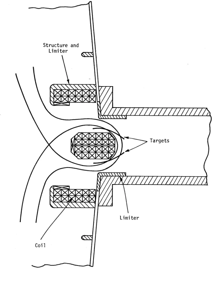
As is shown by Fig. 1, the toroidal hybrid divertor proposed here is a T-shaped coil with short horizontal arms but long vertical legs extended in a poloidal direction. All the legs will bend toward the plasma and be contoured like the plasma surface. The null trace is an arc which nearly has the same curvature of the plasma surface. The height of the divertor is larger than the
plasma minor radius. qg will become 6 or less for this divertor. This is about half of the qg) of a
regular bundle divertor. This means that larger bundles of flux can be diverted in less than 6 turns around the torus. Therefore, the efficiency should be much improved. A Monte Carlo simulation study of diverting efficiency has been started and will be discussed the the future. In addition to the improvement in efficiency another advantage is that the divertor can be made very narrow so that it will fit into a very narrow access of a compact high field tokamak like Alcator. Such an
application will be discussed in the next section. 1.2.3 Toroidal Hy
brid
1)ivertor for Alcator CThe plasma edge conditions of Alcator have very high particle and power densities (about 5 X 10" cm- and 5 kW/cm2) which is near reactor regime. Due to this high power density, the limiter cannot last very long. Thus, Alcator would be a very significant test for a divertor. The access slots in Alcator C are only 4.5 cm wide and 30 cm tall. It is quite a challenge to design a divertor which can fit such a narrow port. Utilizing the full space as much as possible, the half-width is chosen to be the horizontal opening of the port. The divertor must therefore be built in two halves, each inserted separately into the vessel. The overall divertor width is slightly larger than the port opening. Based on this concept the divertor magnetic configuration is shown in Fig. 2. The coil configuration is shown in Fig. 1. The plasma and divertor parameters are listed in Table 1. The current density is 180 kAmp/cm2. The divertor has to be pulsed. To test the concept a 20 ms pulse is sufficient. The coils are precooled by liquid nitrogen (to 70 K) or liquid helium gas (to 15 K). For 20 ms flat top and 2 ms rising and decaying time the temperature rise is 75 K. It takes 5 minutes to cool down after the pulse. major advantages of such a small pulsed system are that: (1) the net force is small (less than 12 kN in this particular design) and easy to handle; and (2) the fabrication is much easier and less expensive. The divertor flux bundle is shown in Fig. 3a. The flux bundle is now expanded vertically. The null trace is shown by Fig. 3b. The trace has the same curvature as the plasma surface. The calculated qg is 6. These two effects will improve the efficiency of the current bundle divertor. The comparison of ripple of the divertor studied is shown in Fig. 4. The ripple has been drastically reduced and the zero ripple has been moved further out from the axis.
REFERENCES
[1] T. F. Yang, et al., PFC/JA-81-4 (1981).
[2] Stott, P G., Wilson, C. M., Gibson, A. The Bundle Divertor- Part 1, Magnetic Configuration, Nuclear Fusion 17 #13 (1977) 481.
Table 1
a.) Alcator C Plasma Parameters for Divertor Operation R=64cm
a = 14cm B, = 5Tesla
qj) '- 4
b.) Alcator C Bundle Divertor Parameters (see definition on Fig. 2)
xO e ye Ze I (kAmps)
80 10 2.2 15 180
80 15 3.3 15 180
81 15 3.3 16 180
I2T
a- U - -. -- - - -r -, #F aS-o 44- S.-eto r-It 0 - --o -+L && 3± CL ra be III SL Is of Ts Li ml lb 'a 'S 4-0 3 4J u -V) .,e-L
Structure and
Limiter
///////////
Targets
Limiter
Coil
-C-3 D .-f
Z_
0 -a 0 a-oz- o-o:-0 O-i)z -) > x 0-II-0
cz
I-0 LJ -I Dz
0 41 C-) 0 4-4 0 -.H a) 0 (1) LH a) -Lj_ la) 4-) H Ha
bl-
O'Ll-'r' I CIO: 'ZO'01
o I I L WO)2. 5
"T
SOLENOIDAL
COILS
I
i"
"T
/
COILS
Ke
//
II
1,
/
/1
I//
/
/,
//
--
~-
---00,0
0,5
---
-.
0
RIPPLE
1.0
X
= (R-R)/a
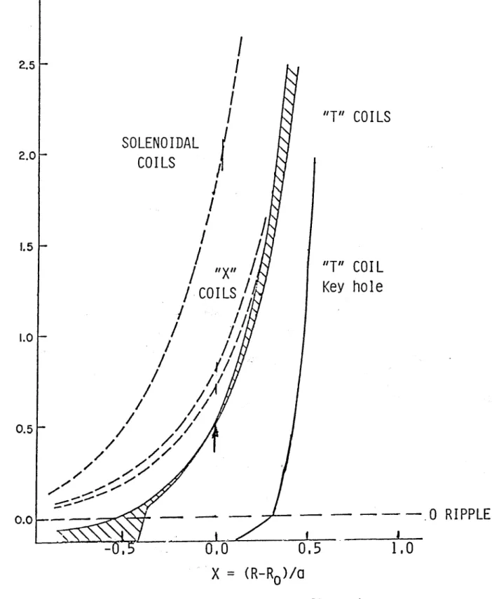
Fig. 4. Divertor ripple on axis for the configurations
studied. The ripple for single "T" and cascade are the lowest. They all fall within the shaded region.
3.01-COILS
COIL
y
hole
2.0 1.5 1.0 0.50.0
I1.3 TEXTOR DIVERTOR DESIGN
1.3.1 Introduction
The overall objectives of TEXTOR [1], are to evaluate the processes leading to impurity build-up in tokamaks and to damage of the first wall under different operating conditions; to search for appropriate first wall materials, structures and temperatures that are optimized with respect to particle release and wall material behavior; and to develop and test methods to control the boundary. To accomplish the first objective, some control mechanism is needed. TEXTOR has given the bundle divertor considerable thought as has been reported in the Divertor Workshop held at Culham Laboratory in England in 1977. There are provisions for two such divertors to be installed.
An optimization study [2] has shown that the performance of the bundle divertor is favored in a large device with a large aspect ratio among the existing tokamaks. TEXTOR is thus a good device for operating a bundle divertor.
High poloidal beta and long pulse (5-10 seconds) may require effective impurity control methods of which none currently exist. The bundle divertor has proven at least 30% efficiency at less favorable conditions, hence this option should be vigorously investigated and supported. The simplified plane view of TEXTOR with the implementation of an advanced bundle divertor is shown in Fig. 1. Figures 2 and 3 show cross sectional and trimetric views. There are two large ports of 60 x 80 cm2
each on the midplane of the vessel for housing the bundle divertor which are currently being used as beam dumps. With these ports used for the bundle divertor, the beam dump could still fit into the large space between the vacuum vessel and the divertor. The bundle divertor shown here is a monolithic single unit construction which can be externally assembled and then inserted into the existing space. The divertor coil can be of either copper or superconducting conductors. In the case of a copper conductor the coils can be operated at steady state with 7 MW of power consumption.
1.3.2 TEXTOR Bundle Divertor
The magnetic configuration of a reference bundle divertor designed for TEXTOR is shown in Fig. 4. The diverted magnetic flux design was expanded to reduce the thermal load on the target and increase the pumping efficiency Coil parameters are listed in Table 1 The plane view and cross sectional view of this divertor as if installed on TEXTOR are shown in Figs. 1 and 2.
The divertor coils are cascade T-shaped. The width is limited by the space between the two adjacent TF coils, as the coils are designed to be inserted into the tokamak or pulled out as a single unit. The cascade T-shaped coil configuration dramatically reduces the ripple and current density in the conductor while making the divertor compact. The magnetic flux surfaces were found to be nonergodic and the particle confinement from the guiding center orbit study was also improved. This bundle divertor would not only provide for a long pulse impurity control experiment on TEXTOR, but the results will also be significant for reactors generally since this cascade-T bundle divertor performs better on larger machines.
In order to select an appropriate dimension and location of the divertor coils within the constraints of the existing space, a variation study has been done. The current and location may
be readjusted as the design is refined.
The preliminary thermal characteristics are listed in Table 1. The thermal analysis was done using the same conductor as was used for the ISX-B bundle divertor. The conductor configuration is shown at the bottom of Table 1. The conductor of each turn has a cross section of 1.1 X 1.1 cm and the diameter of the cooling channel is 0.4 cm. There is a thickness of 1 mm insulation material (fiberglass tape and G-10 epoxy). -The total number of turns is 384. The parameters listed are for steady state operation. The power consumption is less than 7 MW.
The engineering concept of the divertor is illustrated by the trimetric view shown in Fig. 3. The coil containment structure can be a monolithic unit; hence there is only one mechanical vacuum seal, as indicated by dashed lines on the front face, which will be bolted to the flange of the vessel. The passage for the diverted flux and plasma may be machined into the divertor housing. The top, bottom, side and back panels are all removable so that windings can slide into place and be available for improvement or repair. The divertor assembly is attached to the TF coils by two horizontal bars on the top and bottom. The bars are keyed to the divertor casing and attached to the TF coil structure by a cylindrical bearing. The net magnetic forces are transmitted to the TF coils; therefore the force balance for axisymmetric system is restored. This design will minimize the installation and disconnection time. The divertor assembly can be freed and extracted simply by lifting up and dropping down the holding bars.
1.3.3 Comparison of the Cascade T-Shaped and Conventional Circular Divertors
For comparison purposes, three different magnetic divertor configurations for TEXTOR using a DITE MK-type [3,4] divertor have been calculated. The MK-type divertor has planar circular coils. The divertor performance and coil current are very sensitive to the size (radius of the circular coils) and angle a as shown in Fig. 5. The cross section of the coil is also shown in this figure. Comparative coil parameters, current, current densities, and ripple on axis are given in Table 2.
The relative position of the divertor is given by X located on the front surface. The size is given by the width of the front opening. The current requirement for the advanced type divertor at the corresponding location W is given in the last column of Table 2. (The baseline divertor center is located further away at 245 cm.) Figure 6 compares the ripple MK-type and the advanced divertor.
All DITE MK-type divertors have to be placed very close to the plasma and have a larger size. The current density is at least twice as large as the case of the cascade-T type. The resistive heating for the MK-type is judged to be too large for long pulse operation. All the MK-type coils would interfere with the TF coils and the installation and service would be difficult. Due to space constraints the size of the MK-type divertor has to be reduced when it is moved away from the
plasma, whereas for the advanced type the size can be fixed for various radial positions.
The advantages of the advanced type TEXTOR bundle divertor may now be summarized as follows:
(1) The current density is low enough to permit steady operation at reasonable power consumption. (2) The ripple is low and flux surfaces are not ergodic. Thus the effect of the divertor on the
confinement would be much less.
(3) The null trace is straight vertically or concave toward the plasma and conforms better to the shape of the scrape-off layer; the diversion frequency, qg, is thus smaller.
(4) The successful experiment and data would be reactor significant.
REFERENCES
[1] Technical Data 1, Julich, Germany, March 1980. [2] Yang, T. F., et al., MIT PFC/JA-81-4 (1981).
[3] Stott, P. E., Wilson, C. M., Gibson, A., "The Bundle Divertor-Part 1; Magnetic Configuration", Nuclear Fusion 17 #3 (1977) 481.
[4] Wooton, Private Communication, February 1982.
[5] Bateman, G., et al., "Bundle Divertor Assessment for INTOR/FED", March 1982.
[6] Yang, T. F., Lee, A. Y., Ruck, G. W., Prevenslik, T., Smeltzer, B., "Design of an Advanced Bundle Divertor for the Demonstration Tokamak Hybrid Reactors", Proc. of the 8th IEEE Symp. on Engr. Probl. of Fusion Research 1 (1979) 615.
Table I
Magnetic and Thermal Design Parameters for TEXTOR Bundle Divertor Reference Design
B, = 2.0 T R, = 175 cm
a
= 50 cm Bnax = 6.0 T Id =1.35 MA-T
Jd = 4.5 kA/cm2Normal Conductor Option for Steady State Operation #Turns = 64 pin = 1.1 MPa Tin = 27 C w = 60 kg/s Vin = 13 m/s pot = 0.15 MPa T,,t = 57 C Teopper = 69
C
Power= 6.5 MW Conductor Configuration Total area/turn = 1.44 cm2 Conductor area/turn = 1.084 cm2 Epoxy area/turn = 0.23 cm2 Coolant area/turn = 0.126 cm2 Table 2Comparison of Advanced Bundle Divertors with MK-type Bundle Divertor of Three Different Sizes
Divertor X Width a I
j
RippleType cm cm deg MA-T amp/cm2 %
MK 235 42.5 450 1.04 8.32 .58
240 42.5 450 1.65 13.2 .87
240 40 600 1.35 12.0 .43
Advanced
Advanced bundle divertor Neutral beam port Bundle divertor-or beam dump Pump port
Fig. 1. Simplified layout of TEXTOR vacuum vessel with the implementation of an advanced bundle divertor. (not to exact scale)
#..-COIL
Divertor coils
Fig. 2. Cross sectional view of the TEXTOR vacuum vessel with divertor coils. (not to exact scale)
C)-x 4- C C
I)
0 V)C Li m S:~ 0)~ -JI U- > CD~ t~~~x :D cC)j< V)I- In 2 aLii C) C/,. C)
1-; Ik S-Ic
01
o-m- O"(- 0-W-ou-1t4') A ul 2 --C2 M rI %Z D'0 02- o&- 0-ca- 0.9 0 N 0 0 Nl 0 C)
x
0 (0 0'a
. a = -o 00 S--- o 0 L-S,- 4-C 4- ro s-r- f 00 C > E or 0."o u. .r- *0 1+- r0 0 -C C I *r- W 0. C. Euo 00t L) C. --X S.U F- r to r -o 5-. -' 0 S.. Ue r-1 0. 0) -C - o r * S-S.. o O-I o 5- .-E C>> 0 - LU-C..)"0-O r-U-.v-l
x
Mem.mi
F19)%
O.
1.4 APPLICAT1ONS OF CRYOGENIC MAGNETIS
1.4.1 Introduction
One possibility for using conventional resistive magnets in fusion reactors is to operate them at low temperatures where resistivity can be orders of magnitude lower than at room temperature, thus reducing the required electrical power [1]. This approach is already used on the ALCATOR tokamak, for example, where the copper Bitter coils are cooled to liquid nitrogen temperatures. However this approach requires power being expended on refrigeration, which increases roughly inversely as the temperature decreases. Simple scaling studies have found a factor of three to ten minimum in magnet power plus refrigeration power, depending on the conductor, at around 10 to 30 K [2,3,10,11,12,13]. Other calculations indicate that the pumping power can be a significant fraction of the total power [9].
The objective of the present work is to identify more accurately the true benefits of cryogenic cooling, taking pumping power, nuclear heating, inefficiencies and magnetoresistance (and other properties) into account. These are particularly important at cryogenic temperatures because small heat inputs can require substantial refrigeration power to remove and completely change the viability of cryogenic cooling. A 11-D compressible flow computer program, CCAN, has been developed for this purpose. We will describe the results of some simple scaling calculations, including a comparison between cryogenic magnets (liquid nitrogen or gaseous helium cooled) and water-cooled magnets for use in TEXTOR bundle divertor coils and AFTR TF coils. At present, the compressible flow code is being tested and property correlations established. It will be used to perform a more comprehensive analysis of cryogenic cooling for fusion reactor applications.
1.4.2 Power Requirements
Total power, the quantity to be minimized, is roughly the sum of magnet electrical power, refrigeration power and pumping power. The magnet electrical power is I2R, where R is the resistance and I the current. Resistance is a function of temperature, magnetic field strength, and material. We concentrate on pure copper and aluminum because these are convenient conductors. Stronger alloys could be used because pure copper and aluminum are fairly weak, but would have higher resistivities [3]. Alternately, other pure metals such as sodium can have lower resitivities at sufficiently low temperatures, but would be much harder to work with.
Refrigeration power is roughly QtaiL(Th/Tc --- /t1rfr, where Qtotal is heat input, T7 and T, are the sink temperature (i.e. atmosphere) and the coil temperature, respectively; (Th/Tc - 1) is the refrigeration Carnot efficiency, and qr,,. accounts for the non-Carnot, non-ideal refrigeration cycle
actually used. Heat inputs include resistive heating of the magnet, pumping friction, heat leakage and nuclear heating.
Pumping power is roughly wAp/p where Ap is the pressure drop, w the coolant mass flow rate, and p the coolant density. Pressure drop can be accurately calculated along the magnet coil allowing for compressibility, acceleration and the Joule-Thompson effect (the change of temperature with pressure under isenthalpic expansion).
Summing these terms, the total power required for steady-state operation of cryogenically cooled magnet coils is
P= Am dx
+
1/
dp[1 +
77ref1
+ eat T- (16 Upup
p rfr lrefr(Tcwhere P is the total power, j is the current density, a the copper conductivity, A,, the magnet cross-sectional area, x the axial coordinate, 77ump the pump hydraulic efficiency and Qhct is other
heat sources such as nuclear heating or heat leaks from adjacent structure. Simple Scaling
For a given conductor, the total power P given by Eqn.(1) varies considerably with operating temperature. This operating temperature range governs the selection of coolants and their states. Water (room temperature), liquid nitrogen (60-75 K), liquid helium (below 4.2 K), and gaseous helium (over 10 K) cover the various temperature regimes of interest. Also, below 100 K, the conductors become very sensitive to variations of temperature, magnetic field strength, and material purity.
A simple scaling study serves to demonstrate the advantage of cryogenic magnets. If we neglect pumping power and non-resistive heat sources, and assume constant properties and that the conductor is at the same temperature as the coolant, then Eqn.(1) becomes
P = Peff j2 (2)
Peff =+ ( - (3)
a(T,B,PJR) 1rfrT
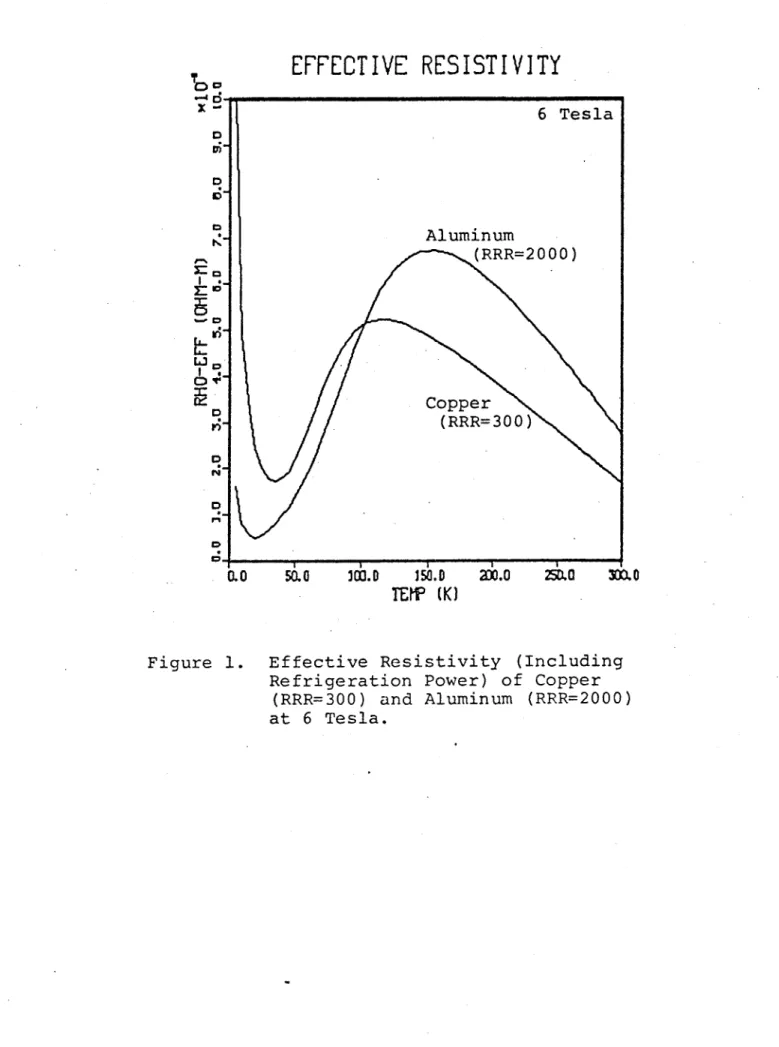
where pfef is the effective "resistivity" of the magnet, including refrigeration power, and T, is the average magnet temperature. Since, A,,,, L and j are fixed for a given magnet, Peff is a measure of the power consumption. Figure 1 plots peff as a function of temperature for copper (RRR=300) and aluminum (RRR=2000) at a magnetic field strength of 6 Tesla. These figures show that steady-state power consumption initially increases as the temperature increases because
resistivity changes slowly but the refrigeration requirements are appreciable. However at some point, resistivity drops sharply and overall power savings of factors of three or so are possible, compared to room-temperature operation. At even lower temperatures, refrigeration power makes cryogenic operation unreasonable again for these conductors. (Superconductors can operate successfully in the 4 K temperature range however, but are not considered here.) Though simple-minded,
Peff demonstrates the possible benefits of operating magnets at cryogenic temperatures. This also demonstrates the disadvantage of steady-state magnets operating at liquid nitrogen temperature.
Compressible Flow Fquations
The analysis is restricted to single-phase, one-dimensional, constant area, steady-state flow. The large property variations at cryogenic temperatures with modest temperature changes (especially for gaseous coolants) requires the use of compressible flow equations to properly determine coolant pressure drop, coolant temperature, conductor temperature, conductor resistivity, and finally magnet electrical power requirement. The resulting equations do not lend themselves to analytic solution, but under the above assumptions with the additional neglect of axial thermal conduction with respect to radial thermal conduction, a simple marching procedure is adequate with straightforward differencing at each axial zone into coolant, conductor surface and conductor bulk nodes. Care must be taken to avoid choked flow, possible flow instabilities [7], critical heat flux with liquid coolants, and thermal runaway in the temperature range where resistivity rapidly increases.
In addition to the above assumptions, we neglect azimuthal property variations and consider only an average axial velocity, v. Then, for the coolant, conservation of mass becomes
d dG
- (pv) = T(4)
where G = pv is the mass flux, p the coolant density. The momentum equation is
pvdv+dp+
,d +pgdz=0 (5)D
where p is pressure, r, is wall shear, x is the axial coordinate, D the hydraulic diameter, g gravitational acceleration and 0 is the conductor orientation angle clockwise from vertical. Expressing the wall shear in terms of a conventional friction factor
f,
dp fG2
G2
dp
x- - pgco
+(6)
dx D2p p 2 d
Finally, the energy equation is
4q"dz