ALGEBRAIC MINIMIZATION AND THE DESIGN OF TWO-TERMINAL
CONTACT NETWORKS by
EDWARD JOSEPH McCLUSKEY9 JRo A.Bo, Bwdoin College
(1953)
BoSo MS, Massachusetts Institute of Technology (1953)
SUBMITTED IN PARTIAL FULFILLMENT OF THE REQUIREMENTS FOR THE
DEGREE OF DOCTOR OF SCIENCE
at
the
MASSACHUSETTS INSTITUTE OF TECHNOLOGY June, 1956 Signature Certifiedof Author
_Departme
of
Ectrical Engineer
g.~
t
~
.Aporil
30o
1956
by
b -
.
_T;hesis Supervisor
Accepted by...
man Departmental Committee on Graduate 1Students
DfE A M N 1' OF EL C't'R ICA L NG IN R ING
MASSACHUSETTS INSTITUTE
OF TECHNOLOGY
C A M ItD G 3 , MA S S C U S S
May 4, 1956
Mr. E. J. McCluskey
Bell Telephone Laboratories
Whippany, New JerseyDear Mr. McCluskey:
This letter is to give you permission to print additional copies
of your thesis by the multilith process, and to submit to the Department
of Electrical Engineering copies thus produced, in lieu of the typed
copies normally required.
A copy of this letter is to be reproduced by the same process and
is to be placed in each copy of the thesis immediately following its title page.
Sincerely yours,
S. H. Caldwell
for the
Department Graduate Committee
SHC:mm
Algebraic Minimization and the Design of Two-Terminal
Contact Networks by
Edward Joseph McCluskey, Jro
Submitted to the Department of Electrical Engineering on
j46i.
,920o
in partial fulfillment of the requirements forthe degree of Doctor of Scienceo
Systems such as digital computers, telephone central offices, etco are commonly constructed so that they operate with signals which only take on two valueso The circuits used in building such systems are called switching circuits
and are described mathematically by means of a two-valued algebra° In designing switching circuits the circuit re-,quirements are reduced to algebraic expressions and then
these expressions are simplified by means of the theorems of Boolean Algebrao The aim of algebra'c simplification is to reduce the amount of equipment needed in the circuit0
The first part of this thesis presents a systematic procedure for writing a Boolean function in the simplest sum of products form. This form corresponds directly to the two-stage, single-butput diode logic circuit using the fewest possible diodeso The procedure developed can be programmed on a digital computer in order to handle func-tions of large numbers of variableso
In carrying out the procedure of part one it is help-ful to know if the function being simplified remains un-changed when some of its variables are permuted (or compli-mented)o A method for the detection of such invariance
(called group invariance) has therefore been developed and is presented in Appendix Ao An extension of this method for determining if a function is totally symmetric (invariant under any permutation of its variables) is also presented0
It is important to know whether a function possesses in-variance properties since special design methods may then be applicable.
In part two of the thesis a method is developed for designing a two-terminal contact network° For relay
switching circuits, contact networks must be designed to control the operation of the circuit relays and to pro-vide output signals. Existing methods of contact network
design are all unsatisfactory either because they are un-systematic or because they restrict the form of the net-work being designed. The method developed here uses the algebraic expression derived by the procedure of part one as a starting point and consists of directly providing a path through the network for each term of the algebraic expressiono Methods are presented for determining how to form each path economically.
Thesis Supervisor S H Caldwell
Title: Professor of Electrical Engineering
ACKNOWLEDGEMENTS.~~ .,
The author wishes to acknowledge his indebtedness to Professor S H. Caldwell who supervised the preparation of this thesis and from whom the author learned the basic
principles of switching theory. The research reported here was influenced strongly by many iscussions with Prof-essor Do A Huffman who contributed much tb the author's under-standing f the problems to be considered. In addition, Messrs S H. Unger, W. J Cadden, ad G. H. Mealy con-tributed helpful comments.
Special mention should be made of Professor t. K. Linvill without whose advice and encouragement this research would probably never have been undertaken.
This research was supported in part by the Signal Corps; the Office of Scientific Research, Air Research and Development Command; the Office of Naval Research; and the Bell Telephone Laboratories.
The author wishes to express his thanks to Miss Arlene McKay who did the final typing.
Last, but far from least, the author must express gratitude to his wife, Roberta, for her assistance in the actual writing and editing of the thesis as well as for her sustaining faiththroughout the entire period of research.
TABLE OF CONTENTS
Page
ABSTRACT 0 0 0 . ii
ACKNOWLEDGEMENTS 0 0 0 0 0 iv
LIST
OF
TABLES
. . .
...
vii
LIST OF FIGURES .
...
viii
INTRODUCTION 0 0 0 0 0 .. 0 1
PART 1 ALGEBRAIC MINIMIZATION
101 Algebraic Symbolism for Relay Contact Networks 5
1.2 The Minimum Sum 12
1.3 Prime Implicants 14
1.4 Prime Implicant Tables 23
lo.5 Row Covering 26
1.6 Prime Implicant Tables in Cyclic Form 30 1.7 Cyclic Prime Implicant Tables and Group Invariance 34
1.8. 4-Terms ,
37
PART 2 CONTACT NETWORK DESIGN
2.1 History of the Problem 39
2.2 General Principles - Essential Contacts 44
2.3 Outline of Design Procedure 47
2.4 The Addition of Paths to a Network - Definition 49 of "Equal Add T"
2o5 The Addition of Duplicate Contacts 57
TABLE OF CONTENTS (continued)
Page 2°6 A Formal Method for Determining the Gij
2,7 Determination of the G..
1j
28 Multiple Desired Paths
2°9 General Desired Contact Subnetworks 2J0 The Order of Forming Paths
SUMMARY AND CONCLUSIONS
....
APPENDIX A AMethod for Determining the Group Invariances of a Transmission .
APPENDIX B Justification for Simplification of Transmission Expressions in Sections 24 and 28 o BIBLIOGRAPHY . . BIOGRAPHY .. . .o . . 61 70 73 82 96 o o · 109 o · 0 115 0 0 0 129
*
·
*
133
o 0 o 135 viLIST OF TABLES
Table Page
1ol-l Boolean Algebra Theorems 9
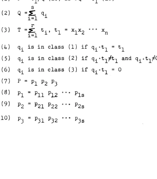
2o6-1 Summary of Notation 68
26-2 Expressions for Pli P2i' P3i 69 2.9-1 Table of Combinations for T1 2 and T1 2 (h=l) 85
LIST OF FIGURES
Figure Page
1.1-1 Determination of Over-all Transmission 6
for Series-Parallel Networks
101-2 Determination of Over-all Transmission 8 by Path Tracing
1.1-3 Circuit Specifications 10
1.3-1 Determination of Prime Implicants for 19 Transmission T =(O 2,496,7,8,10,11,12,
13,14,16,18,19,29,30)
1.3-2 Example of the Two Ways of Forming a 21 Character Having Two Dashes'
1.4-1 Prime Implicant Table for the Transmission 23 of Fig. 1.3-1
lo5-1 Determination of the Minimum Sum for 27
T =(01,2,3,7,14,15,22,2329,31)
1.5-2 Prime Implicant Tables for T = -0,1,2,3, 28
6,7,14,22930,33,62,64,71,78986)
1.6-1 Determination of Basis Rows for a Cyclic 31 Prime Implicant Table
1.7-1 Determination of the Minimum Sums for 35
T = Z(O0,l,2,5,6,7,9,1l1,ll13,14,15).
1.8-1 Determination of the Minimum Sum for the 38 Transmission T = £(5,6,13) & (9,14) where
9 and 14 are the -termso
2.1-1 Network for Transmission T =0,1,2,13,14) 40 2.1-2 Network Designed by Shannon M-N Method. 42
Transmission is T = l(O,5,9,14,15)
LIST OF FIGURES (continued)
Figure Page
262-1 Networks for Transmission T = (3,5,7, 45 1Q0,14) showing non-essential and
dup-licate contacts
23-1 General Form of Network Whose Transmission 48
is the Sum of Two ms-terms
2o4-1 Design of a Contact Network Having Trans- 50 mission T = -(4,19,20 23,30,31)
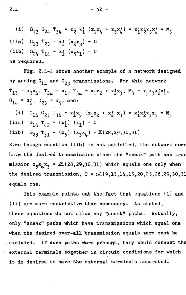
2.4-2 Design of a Contact Network-Having Trans- 52 mission T = 9,l3,14,15920,25,28s29,.30,31)
2 4-3 Design of a Cntact Network Having Trans- 56 mission T = (3,7,8,lO,14,15')
2.5-1 Design of a ContactNetwork aving Trans- 58 mission T = Zl,3,4,6,24) sing One
Dupli-cate Contact
2°5-2 Design of a Contact Network Having Trans- 59 mission T =E(4,5,13,192329,31)
2.7-1 Example of the Determination of the Gij 72 for a Network
28-1 Addition of a Total Path to a Network When 74 Two Desired Paths are Present
2.8-2 Example of thd Addition of a Total -Path to 78 a Network When Two Desired PathS are Present
2°8-3 The Addition of a Total Path to a Network 80 When Three Desired Paths are Present
2o9-1 Example of the Addition of a Total Path to 83 a Network When the Desired Contacts Form a
Loop
2°9-2 General Form of Network with Subnetwork of 84 Transmission h Added
LIST OF FIGURES (qontinued)
Figure Page
29-3 Example of the Modification of a Network 89 Containing Two Desired Contact JLaops to
That Only One Desired Contact Path Remains
29-4 Final Network for the Example of Fig. 29-3 90 2°9-5 An Example of the Breaking of'Branches in a 92
Graph So That Only Paths Remain
209-6 Example of the Use of an H-Subnetwork when a 95 Single Desired Contact Path Exists
2o10-1 An Example of a.Distinguished Network with 98 the Contacts Which are Only in One Path
Shown in Boxes
210-2 The Network of Figo 210-1 with the p4 or 99 P4 and p3 Paths Removed
210-3 An Example of the Design of a Non-Distinguish- 102 ed Network Having Transmission wx + wy + wz +
xyz
210-4 A Non-Distinguished Network Realization for 103 the Transmission T = vlwVxlyz + vwxyz +
vw'xyVz + vxyVz of Fig 210-1
2o10-5 An Example of a Network Design in Which a 107 Given Path Can Be Added by Means of Two
Methods
A-1 Transmission Matrices Sh4wing Effect of 117 Interchanging or Priming Variables
A-2 Partitioning of the Standard Matrix for 120 T = (4,5,7,8,9,ll 30, 3349)
A-3 Transmission Matrices for T = (0,6,9,12) 123 A-4 Transmission Matrix for T =-(3,5,6,7) = 126
S2, 3 (Xl 2, x3 )
A-5 Determination of Totally Symmetric Trans- 128 missions
INTRODUCTION
Digital computer circuits, automatic telephone ex-change circuits, and automatic traffic control circuits are examples of switching circuitso The distinguishing feature of these circuits is that they operate with binary signals; that is, signals which have only two stable values (off or oi, high or low, ground or no ground, etco). Such circuits
can be constructed with relays, diodes, vacuum tubes, tran-sistors, magnetic amplifiers, etco Te theory to be develop-ed here deals with general properties of switching circuits which are independent of their particular physical components.
A combinational circuit is one in which the outputs at a given instant of time are determined only by the inputs at the same instant of time; when the outputs depend also on previous inputs, the circuit is called sequential. The
prob-lem of reducing the specifications for a sequential circuit to specifications for several combinational circuits has ef-"fectively been solved [Hl]o
In 1938, Shannon CS1] showed that Boolean Algebra could be used to design combinational switching circuits (contact networks). In general form, the design procedure consists of: (1) writing the contact-network requirements as an algebraic expression, (2) simplifying this expression by use of the theorems of Boolean Algebra, (3) determining a contact network whose transmission equals the simplified algebraic expression
A systematic method for writing an algebraic ex-pression which corresponds to a given set of circuit require-ments was presented by Montgornerie ~t1lo He introduced the idea of a table of combinations (called a truth table by logicians).
Methods for simplifying algebraic expressions were published by Aiken [SCL1], Veitch VI], Quine Q1], and
Karnaugh EK1]o These methods are similar in that they all result in the same type of expression (the simplest sum of -products form) and they all fail when the expression to be --simplified becomes sufficiently complex. Karnaugh's method
is a chart method which is a refinement of the methods of Veitch and Aikeno It is very effective for functions involv-ing few variables but becomes very difficult and unsystematic as the number of variables becomes largeo Quine's method is an algebraic procedure which is rather unwieldy but which is sometimes useful for functions of many variables. The method to be presented in Part 1 of this thesis has certain similari-ties with both the chart and algebraic methods0 However, it
is usually simpler than either method for fuhctions of more than six variables and can always be systematically carried to completion. In addition it appears that the method to be presented here can be programmed on a digital computer without requiring excessively large storage capacity or computing time0
In connection with this method for simplifying algebraic
ex-pression- a method for determining group invariance rS2 or total symmetry C21 has been determined. This method is pre-sented in Appendix A,
In Shannon's original paper CS1], the design pro-cedure actually consisted of writing the simplest algebraic expression (in the sense that there are the fewest possible variable appearances) corresponding to the circuit
require-merits and then drawing the corresponding contact network direct-lyo This procedure has two defects. There is no systematic method for obtaining the simplest algebraic expression and .only series-parallel networks will result. Numerous examples
exist of nonplanar or bridge-type networks which use signi-ficantly fewer contacts than the corresponding series-parallel network. In a second paper ES2], Shannon presented another method for designing a contact network. The success of this method, called the Shannon MN synthesis, depends on the
de-signer's aility to recognize permissible circuit modifica-tions which very frequently destroy the series-parallel charac-ter of the network while at the same time reducing the number of contacts included, While this method can result in non-planar or bridge-type networks, it is not truly general since the structure of the resulting network is arbitrarily assumed to be of a certain general form. A matrix method of design
-4-has also been presented HS1]. This method does not place any restrictions on the form of the final network, but it
lacks any systematic procedure and in addition is cumber-some to actually carry out. The method for designing contact networks which is presented in Part 2 of this thesis is es-sentially different from any of the previous methods. The required algebraic expression is that obtained by the method
of Part 1. Since no restriction is placed on the form of the final network, this is a general method. A systematic approach is given and all algebraic manipulations are cor-related with the corresponding effects on the actual network.
1.1 PART' 1
ALGEBRAIC MINIMIZATION
1.1 Algebraic Symbolism For Relay Contact Networks
Each relay will be denoted by a symbol such as X1, Y2,
etc. Contacts belonging to the X1 relay will be designated
by x1 if normally open and by xl if normally closed. It is common practice to interpret these contact designators as transmissions by setting x = O, xl = 1 when relay X1 is
unoperated and xl = 1, x 0 when relay X1 is operated.
The symbols 0 and 1 represent open and closed circuits re-spectively.
A series connection of contacts xl and x2 has the
trans-mission xlX2: This function equals one only when both xl and
x2 equal ones and the series connection of xl and x2 is a
closed circuit only when both x and x2 are closed circuits.
Similarly, the transmission of a parallel connection of con-tacts x1 and x2 can be written as xl + x2, if it is postulated
that 1+1=1. This postulate is a statement of the fact that two closed circuits in parallel are indistinguishable from a single closed circuit.
The over-all transmission of any planar, nonbridge (series-parallel) network can be written directly. See
Fig. 1.1-1. First, transmissions are written for all series or parallel connections of contacts, then each such connec-tion is replaced by a single contact designated by the appro-priate transmission. This process is repeated until only one contact remains. The associated designator is the desired over-all transmission.
5 6 5 -x3 X1 X2 x1x2 X3+X4 xIx2(x3+x4)
HI
F-
o-
-
H--
t
-
-i-
°-o
x4 (a) T = xx 2(x3 + x4) X1 x2 Xx2 XlX23 XI5
,
I
I
I
X4 -X3+X4 X2 X2+X1XH X3+x4 X2 x'Ix X1X X1 2 + x3 + x4)(x2+x 5) (x3+x4)(x2+xix5) (b) T xlx 2 + (x3 + x4) (x + xlx5) Figure 1.1-1Determination of Overall Transmission for Series-Parallel Networks.
- 7
-This method is not directly applicable to nonseries-parallel networks. Another method, which works for all net-works, consists of tracing all paths from input to output, writing the transmission of each path, and then forming the over-all transmission as the sum of the individual path trans-missions. See Fig. 1.1-2. Each path transmission will be a product of literals, where a literal is defined as a vari-able with or without the associated prime (x1, x are literals).
The input and output terminals are connected together only when all contacts of at least one of the paths through the network are closed. The over-all transmission can equal one only when at least one of the product terms equals one; that is, when all literals of at least one product terms are equal to one.
It has been specifically postulated that 1+1=1. Other postulates which have been implicitly assumed are: 0+1=1+0=1, 0+0=0, OtO=O, 01=1.0=0, 1.1=1, 0'=1, 1'=0, and xl = 0 if xl/l,
x1 = 1 if xlOo Since these postulates are identical with the
postulates of Boolean algebra, the switching algebra developed here is actually a Boolean Algebra and all the Boolean Algebra theorems apply. This was pointed out by Shannon in a paper
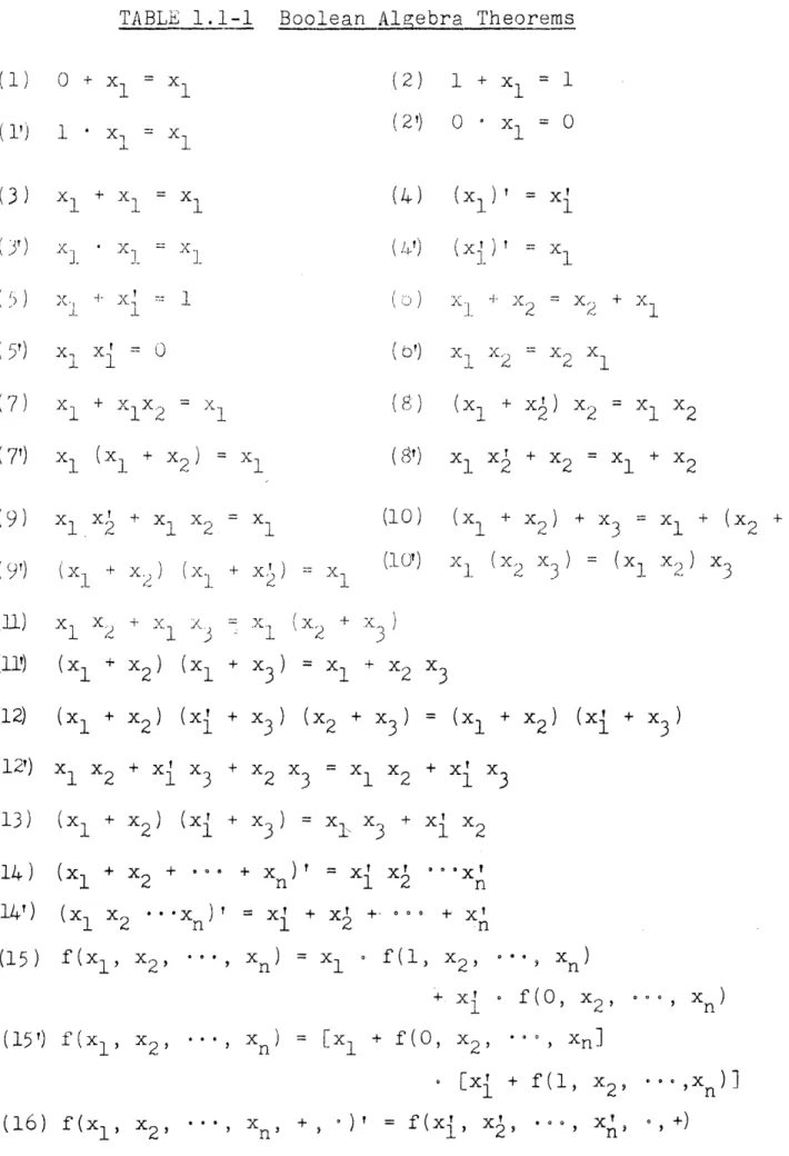
which discusses the theorems in detail [S1]. Table 11-1 is a list of the Boolean Algebra theorems commonly used.
8
X3
0 .-__. 1I
O 10 - 2
--(a) Series-Parallel Network
0
T = x 1x2+ xx 3x5+ xx 3x2+ xx 5
(1) (2) (3) (4)
(b) Bridge Network
Figure 11-2
Determination of Overall Transmission by Path Tracing. T = x1X2X3+ (1) xlx2x4 (2) 0 r ._ _ _ 1.AI ... __ s.... I I - -I I
1.1
TABLE
1.1-1
Boolean Algebra Theorems
(1) 0 + X1 = x1 (1') 1 (2) 1 + x1 (2') 0 * - = 1. x1 X1 + X1 = X1 '1 1 *i. __ _~~z 1.. (4) (Xl) = X1 (,..') (Xj ) _ ' = _~= X, 1: . 0) (o') (7) xI +
XlX
2(e}) ( x
+
X )
X2 = X1 X2 (7')x
1(x
1+
x
2)
= xI (9) x1 x12
+ X11~2
X2 = X1 (8') x1 X + X2 = x1 + X2 (10) (x1 + x2 ) + x3 = 1x
+ (x2 (9') (XL + x.)X))
+ (xI
1
xI 2-
t
x
3
=
= x1 (10') 1 (x2 x3) = (X1 X,,1...) X X + X X - X 1 2 1 (11') (X 1 + X2) (X1 + x3)(
x +X
3)
x1 2 3 =XL X2(12) (x
1+ x
2) (x
I (12r) x1 x2 + xi x3 (13) (x1 + x2 ) ( i (14) (x1 + 2 + ... (14') (x1 X2 + x3 ) (x2 + x3 ) = (x1 + x2 ) ( + X2 X3 = 1 X2+
1
x3
3
+
x3)
=xl x
3+
x
x
2+ X
n
)'
=xI
1 2
X2
.'.Xn)
=
x +
+
...
n + XI n(15) f(x
i X2... ' x
n
)
f(1,
X2, **e xn) Xn )(15') f(x
1, x
2,
=[X
1 + f(O0x
2,
+
f(1,
(16) f(xl,
+..
Xn 1] X2 , )'+~~~~
= f(Xi, X, = 1 = 0(3)
(5r) ( 5') x: x = 2 2 1 I 2 2 1 (11) + 3 ) x3 x3 + x3 + X1I° f(O,
X2 11 -11 .. I I I~~~~~~~~~~~~~~~~f - -( [- ) ) °, +) . . ) I n9 X ) . . ,10 -x1 x2 X3
T
1 0 0 1 1 xI x2 X3 2 0 1 0 1 x x2x 3 0 1 i 1 xl x2 X3 , 1o
o
1 X1 x x 5 1 0 1 1 x1 x2 x3 61 1 X1 x 2 X3 7 1 1 1 0 x1 X2 X3 (a) (b)Table of Combinations p-terms
1 2 3 + X22X3XXX3 XX2X3 + 3 + X1X2X3
(c)
Standard Sum
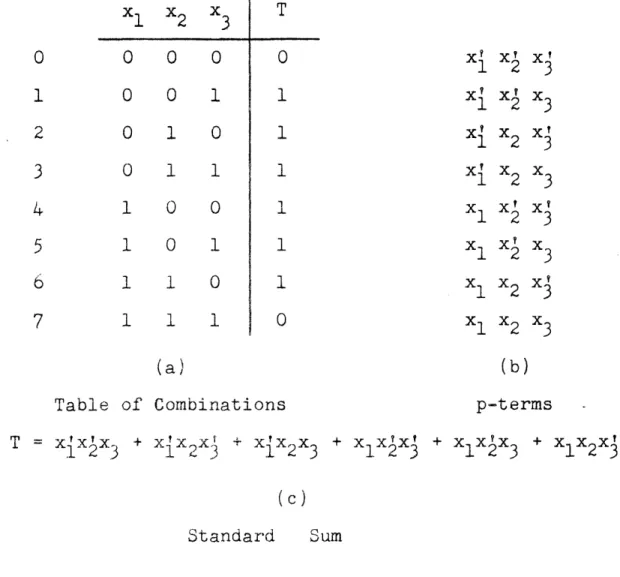
Figure 11-3 Circuit Specifications
For each row of the table of combinations a transmission can be written which equals "one" only when the variables have the values listed in that row of the table. These transmissions will be called elementary product terms (or more simply,
p-terms) since any transmission can always be written as a sum of these p-terms° Figure 10l-3b lists the p-terms for Fig.
1l1 - 11
-The p-term corresponding to a given row of a table of com-binations is formed by priming any variables which have a "zero" entry in that row of the table and by leaving unprimed those variables which have oney" entries. It is possible to write an algebraic expression for the over-all circuit trans-mission directly from the table of combinations0 This
over-all transmission, T, is the sum of the p-terms corresponding to those rows of the table of combinations for which T is to have the value "one." See Fig. ll-3co Any transmission which is a sum of p-terms is called a standard sum [C1].
The decimal numbers in the first column of Fig° lol-3a are the decimal equivalents of the binary numbers formed by the entries of the table of combinations0 A concise method
for specifying a transmission function is to list the deci-mal numbers of those rows of the table of combinations for which the function is to have the value one. Thus the func-tion of Fig. 11-3 can be specified as (1,2,3,4,5,b6)
1 2 12
-1,2 The Minimum Sum
By use of the theorem xlx2 + xl x2 = x2 it is possible
to obtain from the standard sum other equivalent sum functions; that is, other sum functions which correspond to the same
table of combinationso These functions are still sums of products of literals but not all of the variables appear in each term. For example, the transmission of Fig. 11-3, T
x
xlxx3 + xjx2x + xx 2x3 + x x2x3+ X1X2X3 +x
2x3
=131
2
(xxl2x 3 + X{X2X3 ) + (X{X2X
+X
x2xv) + ( x1xx3 + X1X2X3) =(xxk
3 1 2 3 1 2x
1x
2x
3)
+x x2x3
+x
1x
x)
can be written as either T = xX 3 +X 2X + + x2x or T =
x x
3+ ix
2+ x
1xy
The sum functions which have the fewest terms of all
equivalent sum functions will be called minimum
sums unless
these functions having fewest terms do not all involve the same number of iiterals. In such cases, only those functions which involve the fewest literals will be called minimum
sums. For example, the function T = (0,l,3,4,6,7,9,ll,l13,27) can be written as either T= xxllxx + xxlx3 + x5xx x2 l +
x
xxxlX
+ xxx2xl
or
as
Txxx
2x
+ xxx3x 2 + xx4xx +X4 X3X2X 1 + xxx 1 Only the second expression is a minimum
sum since it involves 19 literals while the first expression involves. 20 literals
1o2 13
In principle it is possible to obtain a minimum sum for any given transmission by enumerating all possible equivalent sum functions then selecting those functions which have the fewest terms, and finally selecting from these the functions which contain fewest literalso Since the number of equivalent sum functions may be quite large, this procedure is not
generally practicalo The following sections present a practi-cal method for obtaining a minimum sum without resorting to an enumeration of all equivalent sum functions.
- 4
-1o3 Prime Implicants
When the theorem xlx2 + x 1 - x1 is used to replace by a single term, two p-terms, which correspond to rows i and j of a table of combinations, the resulting term will equal "one" when the variables have values corresponding to either row i or row j of the table. Similarly, when this theorem is used to replace, by a single term, a term which equals "one" for rows i and j and a term which equals "one" for rows k and m, the resulting term will equal "one" for rows i, Jj, k and m of the table of combinationso A method for obtaining a minimum sum by repeated application of this theorem (xlx1 + xlX2 = x1 ) was first presented by Quine Q11,. In this method, the theo-rem is applied to all possible pairs of p-terms, then to all possible pairs of the terms obtained from the p-terms, and so on, until no further applications of the theorem are possible. It may be necessary to pair one term with several other terms in applying this theorem0 In Example 1o3-2 the theorem is applied to the terms labeled 5 and 7 and also to the terms labeled 5 and 139 All terms paired with other terms in ap-plying the theorem are then discarded,; The remaining terms are called rime ime implicants [Q1]. Finally a minimum sum is formed as the sum of the fewest prime implicants which when taken together will equal "one" for all required rows of the table of combinations0 The terms in the minimum sum will be called minimum sum terms or ms-terms0
1.3 - 15 -Example 1.3-1 T = (3,7,8,9,12,13) Standard Sum: T = xx2x + xlx2x3x + xlxx~ + x1xlx3 + x x2x3xL+ x1x2xIx4
F0o
0 1 1 10 1 1 . 1 1 1L
7 l8
9L
JL
13j
Note: The bracketed binary and decimal numbers below the sum terms indicate the rows of the table of combinations for which the corresponding term will equal "one". A binary character
in which a dash appears represents the two binary numbers which are formed by replacing the dash by a "0" and then by a "1". Similarly a binary character in which two dashes ap-pear represents the four binary numbers formed by replacing the dashes by "0" and "1" entries, etc.
XlX2
1 2 3 4 3X
4+ XX
1 2 3 4 2X
XlX2
1t
XX
34XX2X3X + X1XX2 3 4 1 2 3
1 00
L
0
l
100
0
- 16 -X1X2x>x, + X1X2X = xlx 2x [1°]
ii°]
2
1 0. 11 1 0 12 13 12113 X1X2x3 +X1X 2x x1 x310
0
-
r1
i
I
1
-fo0
8g9 12,13 L89,12,3 Prime Implicants: 1 X3 X 1 X X43 4
9,120-8,91213L
Minimum Sum: T = XX + XX X 4 xExample
13-2
Standard Sum: T XX1 2 2X xX34 4 + +2 X2X3X4 4 + XX1 2 3423 X1X2 X3(0
1
XjX2XX 4 + XX2X3X4 = xlx2 x4K
.J
1i .- J 1 0 1 1 1 1 - 1 5L-
7J L.-~~ j
5,7 7 1.3 1 13,7
T2-(5,7,12,13)
1 00
10
- 17 -Xx2X3X4 + XlX2XX4 X2X3x X12X3X 4 1 2 3 4 XlX2X3
1
0
1 0
1
0
l
1o
12 13 12,13Prime
Implicants:
xjx
2x
x2x
xx
O1- Il O 1 0 1 -5,7 5,13 12,13 Minimum Sum: T x= T x2xxx 4 + xx
2x3
4 + XX2 3Quine's method, as illustrated inExamples 1l3-1 and 1l3-2, becomes unwieldly for transmissions involving either many
variables or many p-terms° This difficulty is overcome by simplifying the notation and making the procedure more sys-tematico The notation is simplified by discarding the expres-sions involving literals and using only the binary characters. This is permissible because the expressions in terms of literals can always be regained from the binary characters. The theorem being used to combine terms can be stated in terms of the bin-ary characters as follows: If two binbin-ary characters are
1.3
- 18-identical in all positions except one, and if neither charac-ter has a dash in the position in which they differ, then the two characters can be replaced by a single character. which has a dash in the position in which the original characters differ and which is identical with the original characters in all other positions.
The first step in the revised method for determining prime implicants is to list in a column, such as that shown in Fig° 13-la, the binary equivalents of the decimal num-bers which specify -the function° It is expedient to order these binary numbers so that any numbers which contain no 1's come f il.rci, followed by any numbers containing a single
1, etc. Lilnes sould be drawn to divide the column into
groups of Sbiary umbers which cntain a iven number of 1'sO
The th.eorernm
stateu above is applied to these binary numbers
by comparing each number ith all the numbers of the next
lower gro up
0Other pairs of numbers need not be considered
since any two numbers which are not from adjacent groups must
differ
in more than
on;
binary
igito
For each number which
has 's -WlreerevEr the nu.,be-r (from the next upper grqup) with
which it is being compared has s, a new character is formed
according to the theorem
A check mark is placed next to each
number
which
is used in forming a new character.
The new
1.3 I X5X4X3X2X1
0
0
00
o
/0 2
2
00010'
04
4 00100Z 8 8 ooo o0 0 16 16 1 0000/
2 66
ooo/
210
6 001 1 0 2 10 10 0 10 1 0/
2
18 12 O io /O 46
18 1 o0 1 429 '2/
8
10
7 0 08 1 1 8 12 11 0 1 0 1 1 / 16 18 13 0 0 11 14 29 0 1 01110 1 1 0 16 10 6 77 10 11 30 111
1 012
13(a)
12 14
18 19 13 29 14 30-
19 -II X5X4X3X2x1 O O - 0/00-00
0 - 0O O /-000
O 0
0
-oo1 o
O - O 1 0/'- 0
O1
01
O 0 1 - / 0 - 1 0 0 0 1 0o- o oo1 -o O \/'1
In rl n / 11 --
0110-011-0
00 1 1-1101
-0
1110
0 1 1 -O (b) IV02
4
0.2." 8 0 2 16 04 '8 2 6 10 4 6 12 8 1012 III x5x4x3x2x160
0
- - O
%/
lo
- O - O
/ 18 - 0 0 - 0 12 0 - - 0 014 0
- 1 0
14 0 - 1 - 0 % 14 0 1 - - 0 (C) /v
' X5X4X3X2X10 2 4 6 8
10 12
14
O
-
O
(d) Figure 1.3-1Determination'of Prime Implicants for Transmission T = (0,2,46,7,8,10,11 1213 ,14,16,18, 19,29,30)
103 - 20
-which is again divided into groups of characters -which have the same number of l'so The characters in this new column will each contain one dash.
After each number in the first column has been considered, a similar process is carried out for the characters of column two. Two characters from adjacent groups can be combined if they both have their dashes in the same position and if the
character from the lower group has l's wherever the upper charac-ter has l'so If any combinations are possible the resulting
characters are placed in a third column such as Fig. lo3-1c, and the Column II characters from which the new characters are formed are checked° All the characters in this third column will have two dashes. This procedure is repeated and new
columns are formed (Fig.
1,;3ld)
until no further combinations are possible. The unchecked characters which have not entered into any combinations, represent the prime implicantsoEach binary character is labeled with the decimal equiva-lents of the binary numbers which it represents (see note in Example 1l3-1)o These decimal numbers are arranged in increas-ing arithmetic order. For a character havincreas-ing one dash this corresponds to the order of its formation: When two binary numbers combine, the second number always contains all the l's of the first number and one additional 1 so that the second number is always greater than the first0 Characters having
-
21-two dashes can be formed in 21-two ayso For example, the charac-ter (12,13,14,15) can be formed either by combining (12,13) and
(14,15) or by combining (12,14) and (13,15) as shown in Fig, 13-2
0 0000
0 2 00
0
0 246
0--0 O
2 0 0
1
o 4 o o o
(O 4 2 6 0
o0)
-4
01
0
0
2
6
0-
1 0
6 0 1 1 0 6 1 0
Figure
1,3-2
Example of the Two Ways of Forming a Character Having Two Dashes
Similarly, there are three ways in which a character having
three dashes can be formed (in Fig. 1i3-1 the
,2,4 6,8,10,1214
character can be formed from the 0,2,4,6, and 8,10,12,14 charac-ters or the 02,g,109 and 4,6,129'14. characters or the 0,4,8 12 and 26,10,14 characters), four ways in which a character having four dashes can be formed, etco
In general,
any character
can be formed by combining two
characters whose labels form an increasing sequence of decimal numbers when placed together, It is possible to shorten the
process
of determining
prime implicants
by not considering
the
combination of any characters whose labels do not satisfy this
requirement°
For
example,
in Fig. 13-l3b the possibility
of
1.3 - 22
-combining the (0,4) character with either the (2,6) or the (2,10) character need not be considered. If the process is so shortened, it is not sufficient to place check marks next to the two characters from which a new character is formed; each member of all pairs of characters which would produce the same new character when combined must also receive check marks. More simply, when a new character is formed a check mark is placed next to all characters whose labels contain only deci-mal numbers which occur in the label of the new character. In Fig. 1.3-1, when the (0,2,4,6) character is formed by
combining the (0,2) and (4,6) characters, check marks must be placed next to the (0,4) and (2,6) characters as well as the
(0,2) and (4,6) characters. If the process is not shortened as just described, the fact that a character can be formed in several ways can serve as a check on the accuracy of the process.
- 23
1.4 Prime Implicant Tables
The minimum sum is formed by picking the fewest prime im-plicants whose sum will equal one for all rows of the table of combinations for which the transmission is to equal one In terms of the characters used in Section 1l3 this means that each number in the decimal specification of the function must appear in the label of at least one character which corresponds to a ms-term (term of the minimum sum).
The ms-terms are selected from the prime implicants by means of a prime implicant table' (Fig.
l4-1)o
Each column of the prime implicant table corresponds to a row of the table0 2 4 8 16 6 10 12 18 7 11 13 1 19 29 30 1 XXxx x x x x * 2 X x x * 3 x x * 6 x x
7
x
x
*8
x
x
Figure lo4-1Prime Implicant Table for the Transmission of Fig. lo3-1
This table was first discussed by Quine Q11. However, no systematic procedure for obtaining a minimum sum from the prime imnlic-nt table was resented.
-
24-of combinations for which the transmission is to have the
value one. The decimal number at the top of each column speci-fies the corresponding row of the table of combinations. Thus the numbers which appear at the tops of the columns are the same as those which specify the transmission. Each row of the prime implicant table represents a prime implicanto If a prime implicant equals "one" for a given row of the table of combina-tions, a cross is placed at the intersection of the correspond-ing row and column of the prime implicant table0 All other positions are left blank. The table can be written directly from the characters obtained in Section 1.3 by identifying each row of the table with a character and then placing a cross in each column whose number appears in the label of the character0
It is convenient to arrange the rows in the order of the number of crosses they contain, with those rows containing the most crosses at the top of the table. Also, horizontal lines should be drawn partitioning the table into groups of rows which contain the same number of crosses (Fig0 14-1)o If, in select-ing the rows which are to correspond to ms-terms, a choice be-tween two equally appropriate rows is required, the row having more crosses should be selected. The row with more crosses has
fewer literals in the corresponding prime implicanto This
choice is more obvious when the table is partitioned as suggested above.
1 .4 - 25
-A minimum sum is determined from the prime implicant table by selecting the fewest rows such that each column has a cross in at least one selected row. The selected rows are called basis rows, and the prime implicants corresponding to the basis rows are the ms-terms. If any column has only one entry, the row in which this entry occurs must be a basis row. Therefore the first step in selecting the basis rows is to place an asterisk next to each row which contains the sole en-try of any column (rows 1,2,3,4,5,7,8, in Fig. 14-1). A
line is then drawn through all rows marked with an asterisk and through all columns in which these rows have entries. This is done because the requirement that these columns have entries in at least one basis row is satisfied by selecting the rows marked with an asterisk as basis rows. When this is done for the table of Fig. 1.4-1 all columns are lined out and therefore the rows marked with asterisks are the basis rows for this table. Since no alternative choice of basis rows is possible, there is only one minimum sum form for the transmission described in this table.
1.5 - 26
-1.5 Row Covering
In general, after the appropriate rows have been marked with asterisks and the corresponding columns have been lined out, there may remain some columns which are not lined out; for example, column 7 in the table of Figo lo5-lb. When this happens, additional rows must be selected and the columns in which these rows have entries must be lined out until all columns of the table are lined out. For the table of Fig. l-5-lb, the selection of either row 2 or row 6 as a basis row will cause column 7 to be lined out. However, row 2 is the correct choice since it has more crosses than row 6 This is an example of the situation which was described earlier in connection with the partitioning of prime implicant tables. Row 2 is marked with two asterisks to indicate that it is a basis row even though it does not contain the sole entry of any column.
The choice of basis rows to supplement the single as-terisk rows becomes more complicated when several columns
(such as columns 2,3, and 6 in Fig. lo5-2a) remain to be lined out. The first step in choosing these supplementary basis rows is to determine whether any pairs of rows exist such that one row has crosses only in columns in which the other member of the pair has crosseso Crosses in lined-out columns are not considered, In Fig. 1o5-2a, rows 1 and 2 and rows 2 and 3
- 27
-T =
(0,1,2,3
,7,14,1522,23
9,29,31)
x5 X4 X3 2 1 '5 x x 3 O O O O O o0 0 1 0 1 0 0 0 ;0 1i 0 2 0 2 0 0 0 1 oI 1 3 0 X2 x1o o o
-/
O O - /0 0
x5 x4 x3 x2 X1 012 3 0 0 0 - -7 15 23 31 - 1 1 1 - 1" 3 0 0 0 1 1/ 2 3 0 7 0 0 1 1 1/ 3 7 0 14 0 1 1 1 0/ 7 15 0 22 1 0 1 1 0/ 7 23 -15 0 1 1 1 1/14 15 0 23 1 0 1 1 1/22 23 1 29 1 1 1 0 1i 15 31 -31 1 1 1 1 1/ 23 31 1 0 0 1 -V 0 - 1 - 1 1 1 0 1 1 1 1 1 1 0 1 1 - -- A 1 \ 1 1. 1 1-
1
1
(7,15,23,31), (29,31),
(22,23), (14,15)] 29 31 1 1 1 - 1(a) Determination of Prime Implicants
T = xx¥x' + x3x2x + X5 4 3 3 2 1
x x x x + XX
t
xx
+
5 43 1
5 43 2
n 1 9 X 7 1J, 9 '' 9G 1 I XIX 3x 2 xy4x3x (c) Minimum Sum * * *(b) First Step in Selection of Basis Rows Figure l o5-1
Determination of the Minimum Sum for T = (0,1,2,3,7,14,15,22,23,29,31) 1 2 3 4 5 6
x~~~~~~~~~~~~~~~~~~~~~~~~~~~~~~~~~~~~~~~~~~~~~~~~~~~~~~~~~~~~
x
__. _
. _:
cX
,, 1 1 1. 5* _ w a
J. -- - I k -J I -, 4 I I q p I A1
'
J.
A u r r u4 ) P , j.+ r u /I J o ou u~ X l J. I 4 ) . . _ I (. 0 O J._~' xt_
__ __, __p__ . b__ _ _ _ _ _ _ _.: .(a) Prime Implicant Table with Single Asterisk Rows and Corresponding Columns Lined Out
n 1 2 1, q Cs q 7 11. 9 fn 71 7 q A A -V rL v~ JI V v rr3 1*jV Cu (1 /V VV Vk
= | X
I
--
=__ __ __
__
.. ~~~~~~~~~~~~~t i I- A
---
-_ _ _ - - -- - -- _ _ _ I x x x I I I.
-x
-_
___
_ ___4
}
I
I
.
=____ ' ' __ ' ' __ - __.I______ 4i __ i 1~~~~~~~~~~~~~~~~
' ] 1 1~~~~~~~~~~~~~~~~~ r(t) Prime Implicant Table with Rows Which are Covered by Other Rows Lined Out
Figure 15-2
Prime Implicant Tables for
T = ;(0,123
6
,7,1L.223033
62
,6
47178~86)
1.5
1 2 3 4 5 6 7 9 * ,I-*I 1 2 3 4 5 6 7 9 9 ** * ,,, - 2 -n 'I 0 n " 76 4,0.5 29
-are such pairs of rows since row 2 has crosses in columns 2,3, and 6 and row 1 has a cross in column 6 and row 3 has crosses in columns 2 and 3 A convenient way to describe this situation is to say that row 2 covers rows 1 and 3, and to write 21, 230 If row i is selected as a supplemen-tary basis row and row i is covered by row j, which has the same total number of crosses as row i, then it is possible to choose row j as a basis row instead of row i since row j has a cross in. each column in which row i has a cross.
The next step is to line out any rows which are covered by other rows in the same partition of the table (rows 1 and 3 in Fig. 15-2a)o If any column now contains only one cross which is not lined out (columns 2 and 3, and 6 in Fig. 15-2b), two asterisks are placed next to the row in which this cross occurs (row 2 in Fig. 15-2b) and this row and all columns in which this row has crosses are lined outo The process of
draw-ing a line through any row which is covered by another row and selecting each row which contains the only cross in a column is continued until it terminates. Either all columns will be lined out in which case the rows marked with one or two asterisks are the basis rows, or each column will contain more than one cross and no row will cover another row. The latter situa-tion is discussed in the following secsitua-tion.
1.6 - 30
-1.6 Prime Implicant Tables in Cyclic Form
If the rows and columns of a table which are not lined out are such that eve'ry column has more than one cross and no row covers another row (Fig. 1.6-lb), the table will be said to be in cyclic form, or, in short, to b cyclic. If any
column has rosses in only two rows (in Fig. 16-lb, column 0 has crosses in rows 1 and 2) at least one of these rows must be included in any set of basis rows. Therefore, the basis rows for a cyclic table can be discovered by first determining whether any column contains only two crosses and if such a column exists, by then selecting as a trial basis row one of the rows in which the crosses of this column occur0 If no column contains only two crosses, then a column which contains three crosses is selected, etco All columns in which the
trial basis row has crosses are lined out and the process of lining out rows which are covered by other rows and selecting each row which contains the only cross of some column is
carried out as described above. Either all columns will be lined out or another cyclic table will result. Whenever a cyclic table occurs, another trial row must be selected0 Eventually all columns will be'lined out. However, there
is no guarantee that the selected rows are actually basis. rows. The possibility exixts that a different choice of trial rows would have resulted in fewer selected rows In
7---- 31 -0 L 16 12 2L 19 2 27 29 1 C x
x
x
x
x
x xX
X X x x'(a) Selection of Single Asterisk Rows 0 4 16 12 24 19 28 27 29 31 -1
1
j t--
r-WI
1 2 3 4 5 6 7 8 9 10 *** 1 2 3 ** 5 6 , 7 8 9 |..* O AJ '4 UJ 1F r- 1 7 40 4 4 ). x XX
X
X X X XX
X
x
x
(b) Selection
of Double
Asterisk Rows L 1 f- 12 1 1 0 9 7 950 '1 1 -1 i r Flx
(c) Selection of Row 1 as a Trial Basis Row (Col. O)(d) Selection of Row 2 as a Trial Basis Row (Col. O) Figure 1 6-1
Determination of- Basis Rows for a Cyclic Prime Implicant Table
1 2 3 4 5 6 7 8 9 10 1 2 3 4 5 6 7 8 9 10 ;- E_ i
:=
r -I _ _ _ _-I _ ¢---1- --- , I aBS. "I., * 2"., .1 . "* ** v _ _ _ _,I I .I.I I -- _ _ I . . I v' ` 3 I I E-I .- ,- f- db-l L f m· I-I I--L. L. · J- C--;·=
I . I r)) isn i. -1 r, -3 3d 37 i~n 6 ) I *I
T
1.6 - 32
-general, it is necessary to carry out the procedure of select-ing rows several times, choosselect-ing different trial rows each time, so that all possible combinations of trial rows are con-sideredo The set of fewest selected rows is the actual set of basis rows.
Figure 16-1 illustrates the process of determining basis rows for a cyclic prime implicant table. After rows 7 and 10 have been selected a cyclic table results (Fig. 106-lb)o
Rows 1 and 2 are then chosen as a pair of trial basis rows since column 0 has crosses in only these two rows. The selec-tion of row 1 leads to the selecselec-tion of rows 4 and 5 as shown in Fig. lo6-lco Row 1 is marked with three asterisks to indi-cate that it is a trial basis row. Figure 1l6-ld illustrates the fact that the selection of rows 3 and 6 is brought about by the selection of row 2 Since both sets of selected rows have the same number of rows (5) they are both sets of basis rows. Each set of basis rows corresponds to a different minimum sum so that there are two minimum sum forms for this
function.
Sometimes it is not necessary to determine all minimum sum forms for the transmission being considered. In such
cases, it may be possible to shorten the process of determining basis rows. Since each column must have a cross-in some basis row, the total number of crosses in all of the basis rows is
1.6 - 33
-equal to or greater than the number of columns. Therefore, the number of columns divided by the greatest number of cros-ses in any row (or the next highest integer if this ratio is not an integer) is equal to the fewest possible basis rows. For example, in the table of Fig.lo6-1 there are ten columns and two crosses in each row. Therefore, there must be at least 10 divided by 2 or 5 rows in any set of basis rows.
The fact that there are only five rows selected in Fig l
o6-1c
guarantees that the selected rows are basis rows and therefore Fig. l.6-ld is unnecessary if only one minimum sum is required. In general, the process of trying different combinations of trial rows can be stopped as soon as a set of selected rows which contains the fewest possible number of basis rows has been found (providing that it is not necessary to discover all minimum sum forms), It should be pointed out that more than the minimum number of basis rows may be required in some cases and in these cases all combinations of trial rows must be considered. A more accurate lower bound on the numberi of basis rows can be obtained by considering the number of rows which have the most crosses. For example, in the table ofFig. 1.5-2 there are 15 columns and 4 crosses, at most, in any row. A lower bound of 4 (15/4 = 3 3/4) is a little too opti-mistic since there are only three rows which contain four
cros-ses. A more realistic lower bound of 5 is obtained by noting that the rows which have 4 crosses can provide crosses in at most 12 columns and that at least two additional rows containing two crosses are necessary to provide crosses in the three remain-ing columns.
1.7 - 34
-1.7 Cyclic Prime Implicant Tables and Group Invariance It is not always necessary to resort to enumeration in order to determine all minimum sum forms for a cyclic prime implicant table. Often there is a simple relation among the various minimum sums for a transmission so that they can all be determined directly from any single minimum sum by simple interchanges of variables. The process of selecting basis rows for a cyclic table can be shortened by detecting before-hand that the minimum sums are so related.
An example of a transmission for which this is true is shown in Fig. 1.7-1. If the variables x and x2 are inter-changed, one of the minimum sums is changed into the other. In the prime implicant table the interchange of x1 and x2
leads to the interchange of columns 1 and 2, 5 and 6, 9 and 10, 13 and 14, and rows 1 and 2, 3 and 4, 5 and 6, 7 and 8. The transmission itself remains the same after the interchange.
In determining the basis rows for the prime implicant table (Fig. 1.7-1(d)) either row 1 or row 2 can be chosen as
a trial basis row. If row 1 is selected the i-set of basis rows will result and if row 2 is selected the ii-set of basis rows will result. It is unnecessary to carry out the procedure of determining both sets of basis rows. Once the i-set of basis rows is known, the ii-set can be determined directly by inter-changing the x and x2 variables in the i-set. Thus no enumera-tion is necessary in order to determine all inimum sums.
-
35 -x4 x3 x2 10 00
00
1 0 0 0 1
2 00 1 0 5 0 1 0 16 0 1 1 0
9 1 0 1 10 1 0 1 07 0 1 1 1
11 1 0 1 1 13 1 1 0 1 14 1 1 1 0 15 1 1 1 1 0, 1 0, 2 1, 5 1, 9 2, 6 2,10 5, 75,13
6, 76,14
9,11
9,13
10,11 10,14 7,1511,15
13,15 14,15 (a) x4 X4 0 0 O O / /J
J
I
'I
I/ x3 x2 x10 0
-O O00 - 0
O O00 -
1
0 10
1--1 0 0 1 1-1
1
1 0
-1 -
O0
1 0 1 1 - 1 -1 1 1 - 1 11-1
11
lJ
1/ 1, 5, 9,132, 6,10,14
5, 7,13,15
6, 7,14,15
9,11,13 ,15
10,11,14,15 (c) X4 X3 X2 X1- -
0 1
-
1
0
-
1 -
1
-
1 1
-1 - - 1 1 - 1 -0 1 2 5 6 9 10 7 11 13 14 15 x x x xx
x
x
x
x x x X x x x x x x X x x x x x (d) / (i) (0,1)+(2,6,10,14)+( 57,13,15)+(9,11,13,15) 0 J (ii) (0,2)+(1,5, 9,13)+(6,7,14,15)+(10,11,14,15)l/
1
Ti = xIxx
+2xl + X
3xl +
X4xi
0
J Tii = x~xl
+ x
X
I
x
3x
2+
X
4x
21
(e)1
/ O ¥1
1 / 1 /Figure
17-1
Determination of the Minimum Sums for T = E (0,1,2,5,6,7,9,10,11,13,14,15)
(b)
. .
36
-In general, the procedure for a complex prime implicant table is to determine whether there are any pairs of variables which can be interchanged without effecting the transmission. If such pairs of variables exist, the corresponding interchanges of pairs of rows are determined. A trial basis row is then
selected from a pair of rows which contain the only two crosses of a column and which are interchanged when the variables are permutedo After the set of basis rows has been determined, the other set of basis rows can be obtained by replacing each basis row by the row with which it is interchanged when vari-ables are permutedo If any step of this procedure is not pssi-ble, it is necessary to resort to enumeration0
In the preceding discussion only simple interchanges of variables have been mentioned0 Actually all possible
permu-tations of the contact variables should be considered It is also possible that priming variables or both priming and permuting them will leave the transmission unchanged0 For example, if T = x x x2 xi + x x x X priming all
the variables leaves the function unchanged. Also, priming x4 and x3 and then interchanging x and x3 does not change the
transmission0 The general name for this property is group invarianceo This was discussed by Shannon in [S21] A method for determining the group invariance for a specified transmission will be presented in Appendix A.
- 37
-1. 8 -Terms
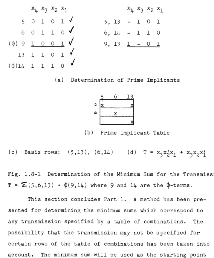
In section 1.1 the possibility of having -entries in a table of combinations was mentioned. Whenever there are com-binations of the relay conditions for which the transmission
is not specified, -entries are placed in the T-column of the corresponding rows of'the table of combinations. The actual values (0 or 1) of these -entries are chosen so as to simplify the form of the transmission. This section will describe how to modify the method for obtaining a minimum sum when the table of combinations contains -entrieso
The p-terms which correspond to Q-entries in the table of combinations will be called -termso These -terms should be included in the list of p-terms which are used to form the prime implicantso See Fig. 1.8-lao However, in forming the prime implicant table, columns corresponding to the -terms should not be included (Fig l8-lb)o The Misterms are used in forming the prime implicants in order to obtain prime im-plicants containing the fewest possible literalso If columns
corresponding to the -terms were included in forming the prime implicant table this would correspond to setting all the
4-entries in the table of combinations equal to 1o This does not necessarily lead to the simplest minimum sum0 In theprocedure just described, the -entries will automatically be set equal to either O or 1 so as to produce the simplest mini-mum sum. For the transmission of Fig0 18-1 the 14 -entry has
V-1.8
-38
-x -x
43 x
2x
1x
4x
3x
2x
1 5 0 1 0 1 5, 13 - 1 0 1 6 0 1 1 0 6, 14 - 1 1 0() 9 1 0 0
1 !
9, 13 1 -
0 1
13 1 1 0 1/
(cp)14 1 1 1 0(a) Determination of Prime Implicants
5 6 13
*x l
x
(b) Prime Implicant Table
(c) Basis rows: (5,13), (6,14) (d) T = x3xIx 1 + X3X2X1
Fig.
lo8-1
Determination of the Minimum Sum for the Transmission T = S(5,6,13) + (9,14) where 9 and 14 are the -termsoThis section concludes Part 1o A method has been pre-sented for determining the minimum sums which correspond to any transmission specified by a table of combinations. The possibility that the transmission may not be specified for certain rows of the table of combinations has been taken into account. The minimum sum will be used as the starting point for the design procedure for contact networks to be presented in Part 2.
PART 2
THE DESIGN OF TWO-TERMINAL CONTACT NETWORKS
2l1 History of the Problem
Usually9 the first step in designing a two-terminal con-tact network is to express the desired transmission as a mini-mum sum° This can always be done by means of the procedure
presented in Part lo A contact network whose transmission equals this minimum sum can then be designed by applying
backwards the method given in Section ll for analyzing series-parallel networks. This will always result in a network which
consists of several branches in parallel, Each branch will correspond to a ms-term (term of the minimum sum) and will be a series connection of contactso For example9 the minimum
sum for the transmission T = (01213 914) is T = xxlx +
xVxvx{ + x4X3X1l which corresponds to the network shown in Fig 2o1-lao
A network designed directly from a minimum sum is not generally desirable since such a network usually contains more contacts than necessaryo It is very often possible to factor a minimum sum before designing the network and thereby obtain a network with fewer contacts. Fig 2-lb shows the network which results when the transmission of Fig 2la is factored
(note that two contacts are saved)0 One difficulty with the method of factorization is that no definite rules can be given for how to proceedo For example the transmission T =(011293
4,11), is written as the minimum sum, T = xx 4 3 + x¥xx 4 2-3 + XX2X1
2x1
- 40
3 I I x3 II X3 x3-...-
1--
-4--Xl (a) Without FactorinXX 3 + XI 4 x4 x ~ lg (nine contacts) XIxIX 4 3 1 + XX3 4 3 1 x 3 x3 i II
x'
1 1 x1 I I (b) With Factoring T = x X (I (seven contacts) + xl)+
x3xFigure
21-1
Network for Transmission
T = X(0,1,2,13,14) I -21ol IX 2 x1 1F ,,l I
x
4xl
1-I
i---· I, ·~~~~~~~~~~~ I' .. . , n III I ' , - L . . n~~~~1 I'. I l II II i! I!I I2.1
- 41
-and factored as follows: T = x1x3 + xx + x
4
3
4 2x+X 3X 2X 1x4
(cx
+ x x)
+
X
2X
1XI
+
X
2XXX
=2x (xj
+ xx
i) +
x
2x
1(x
+x2x1)
=(xI
+x2x)
(x
+
X'X').The second
diffi-culty with the method of factorization is that it restricts the final network to be a series-parallel network. Very fre-quently, bridge or non-planar networks use many fewer contacts than any series-parallel network having the same transmission. Any method which designs only series-parallel networks must be rejected if economy of contacts is important.In 1949, Shannon [S2] presented a design method which does not necessarily result in a series-parallel network. In this method, the desired two-terminal network is formed by
connecting together two multi-terminal networks. See Fig. 21-2. One of these multi-terminal networks, called the M-network, is always a contact tree [C1], [KRW1]. (A contact tree on n-variables is a network which has one input and 2n outputs; the
transmission between the input and each output is equal to one of the p-terms of the n-variables.) The second multi-terminal network, called the N-network, is not of any-special form.
One difficulty with this design method is the fact that it is usually not clear which variables should be included in the M-network. Several possibilities must usually be tested. Another difficulty is that the economy of the design often
r-_ i2<. x3 "3 , I XI II Il X3 1 I 14 .3 II -- x2 1I xl 'XI 1 I I M-Network
N-Network
Figure 2.1-2Network designed by Shannon M-N Method Transmission is T = (0,5,9,14,15) x4
A
jx
I I 3Im
I I " I: _ ! i i i-1C---Ij I 2', F - - - -l I I - - -..
--I !
2.1
- 43-depends on the way in which the N-network is modified to
eliminate contacts. No general rules for these modifications have yet been formulated. The major difficulty with the M-N design is the fact that it assumes that part of the network will be a contact tree. Many transmissions can be realized most economically by networks which do not contain contact trees and hence the M-iN design procedure must be rejected as a general method for designing economical contact networks.
Finally, the matrix method of Hohn and Schissler [HS11 is truly general since no special form of network is assumed. However, no definite rules of procedure are given so that the
success of the method depends on the skill of the designer. All existing methods of contact network design are un-satisfactory either because they restrict the network to be of some special form or else because they depend on the skill
of the designer.