HAL Id: inria-00516016
https://hal.inria.fr/inria-00516016
Submitted on 8 Mar 2011
HAL is a multi-disciplinary open access
archive for the deposit and dissemination of
sci-entific research documents, whether they are
pub-lished or not. The documents may come from
teaching and research institutions in France or
abroad, or from public or private research centers.
L’archive ouverte pluridisciplinaire HAL, est
destinée au dépôt et à la diffusion de documents
scientifiques de niveau recherche, publiés ou non,
émanant des établissements d’enseignement et de
recherche français ou étrangers, des laboratoires
publics ou privés.
Parameterized Specification and Verification of PLC
Systems in Coq
Hai Wan, Xiaoyu Song, Ming Gu
To cite this version:
Hai Wan, Xiaoyu Song, Ming Gu. Parameterized Specification and Verification of PLC Systems in
Coq. 4th IEEE International Symposium on Theoretical Aspects of Software Engineering, Aug 2010,
Taipei, Taiwan. �inria-00516016�
Parameterized Specification and Verification of PLC
Systems in Coq
Hai Wan
D.CST, Tsinghua University, Beijing, ChinaXiaoyu Song
ECE Dept, Portland State UniversityPortland, USA
Ming Gu
School of Software, Tsinghua University
Beijing, China
Abstract—Programmable logic controllers (PLCs) represent a typical class of embedded software systems. They are widely used in safety-critical industrial applications, such as railways, automotive applications, etc. The paper presents a novel method to specify and verify PLC software systems with the theorem proving system Coq. Dependent inductive data types are har-nessed to represent the component specifications. Modular and parameterized specification and verification are proposed. An illustrative example demonstrates the effectiveness of the method.
I. INTRODUCTION
Programmable logic controllers (PLCs) are used extensively in the field of automation, such as automobile plant and nuclear power station. They are getting more and more com-plex nowadays. In order to cope with this situation, modular development of PLC software is adopted. During the modular development, a system is divided into a set of separated mod-ules (or components) and then each module is implemented independently. There are several advantages of modular devel-opment, such as well organized program structure, minimized interconnections among components, information hiding, easy replacement of components, reuse of components.
Besides these advantages to the software development, for-mal specification and verification of PLC software can benefit from modular development as well. In this paper, we present a method of modular and parameterized specifying and verifying PLC software in the theorem proving system Coq [1]. We show how Coq system, especially the dependent inductive data type, facilitates the specification and verification process in various ways.
Components (i.e. Function Blocks [2] in PLCs) are building blocks of PLC systems. For specifying systems, how to model components in a convenient and natural way is of great importance. Record types1 of Coq are deployed to specify
components. Record types can be simple (i.e. without parame-ters) or parameterized. Components that have not parameters, such as RS-flipflop, can be represented by simple records. A parameterized record can be understood as a specification generator that takes some parameters (e.g. natural numbers, transition systems) as input and outputs a specification. Com-ponents, such as TON-timer, can be specified by these records.
1Coq provides a module system whose main purpose is to organize theories
and proofs. Since modules in Coq are not first-class objects, using them to represent components is not convenient. Hence we use record type instead.
In section II-B1 we show an example of how to translate a transition system to a specification. The construction of compound components from subcomponents is also discussed. The construction process is modeled by a function in Coq. The function takes the specifications of subcomponents and the connections as inputs and outputs an instance of the compound component. In some sense, these functions build a link between the implementation and the specification. This link can be used for refinement check in the future. In order to describe the connections, we design two types of connectors for the connections as well.
For the verification phase, record types help to abstract away the irrelevant information. When proving properties, we only need to concern the specification of a component; the implementation details of the component are omitted, which reduces the proof efforts. Local verification and decomposition verification are also possible based on the modular structure of the system. Besides the above benefits, coercion mechanism, implicit arguments, setoid library, section mechanism etc. of Coq help as well.
The rest of the paper is organized as follows. In section II we first give a short introduction of PLCs, then use examples to show how to do modular specification using single records and parameterized records. In section III, we use some prop-erties to demonstrate how modular development facilitates the verification work. Related works are given in section IV and section V concludes the paper.
II. MODULARSPECIFICATION OFPLCS
A PLC system typically consists of a CPU, a memory and input/output points. PLCs are reactive systems in which PLC programs are executed in a cyclic mode. In each scan cycle, firstly the values of sensors are read and mapped to the input points; secondly, the program is executed; finally, the values of output points are mapped to the actuators. In this paper, we consider a dock fire fighting system [3] that consists of a PLC and devices, e.g. a control panel (composed of lights, buttons and joysticks), valves, water pumps, fire monitors and sensors. We use the system to demonstrate various aspects related to modular specification.
A. Variables and Time
A component contains a set of variables. Variables’ types are of the form “nat->...”, where “...” is the type of the variable. For example, Boolean variables are of type BVar which is defined as nat->bool. Given a variable v of type BVar and a natural number n, v n denotes the value of v at the beginning of the n-th scan cycle. Variables are classified into three groups: input variables, output variables and inner variables. There is a frequent used pattern about variables: given a set S, associate each element in S with a boolean variable. This pattern plays an important role in the parameterized specification. We use functions of type S -> BVarto achieve this. This applies to other types of variables. In this paper, we consider discrete time, hence time is defined as natural numbers. In order to attach a time to the beginning of each scan cycle, function f is introduced. f should satisfy the monotonicity property which describes that time can not decrease.
Definition BVar := nat -> bool. Definition NVar := nat -> nat. Definition Time := nat.
Variable f : nat -> Time.
Hypothesis f_mon : forall t, f t < f (t+1).
B. Components
Both atomic components and compound components can be rep-resented by Record type in Coq. A component consists of a set of variables and a set of specifications, which are constraints over the variables. In the sequent Coq codes, some lengthy specifications are omitted in order to save space; they are represented by “...” instead.
1) Atomic Components: Atomic components can be further divided into three categories: the first are the components with no parameters, the second are those with parameters but their structures (particularly, the control flow graph) do not depend on the parameters, and the third are those with parameters and their structures depend on the parameters. For each category, an example is deployed to demonstrate the specification process.
The first category can be represented by Record types with no parameters. Take the RS-flipflop for example. It has two input boolean ports R and S and one boolean output port Q. Q is 0 if R is 1. Q is 1 if R is 0 and S is 1. When R and S both are 0, Q stays unchanged. The Coq codes of a RS-flipflop is as follows. The first line of RSflipflop defines three boolean variables and rsff_specdefines the behavior. Note that RSflipflop does not have parameters.
Record RSflipflop := {
rsff_R:BVar; rsff_S:BVar; rsff_Q:BVar; rsff_spec : forall n, rsff_Q n =
negb (rsff_R n)&&(rsff_S n||rsff_Q (n-1)) }
A TON-timer belongs to the second category. A TON-timer has three ports: boolean input port IN , natural input port P T and boolean output port Q. P T is the timeout value2. IN is used to enable the timer. Roughly speaking, Q is 0 if IN is 0. Q is 1 if IN stays 1 for a period longer than P T . P T can be understood as a parameter that is used to set the TON-timer’s timeout. Hence a TON-timer is modeled by a Record type with a parameter of type nat. Three specifications are deployed to describe the behaviors of a TON-timer (for detailed description of these specifications, please refer to [4]). By applying TONTimer to 3000 we obtain a TON-timer whose PT is
2In PLCs, P T of a TON-timer is a constant.
3000 (i.e. 3 seconds). Note that the structure of TONTimer does not depend on the parameter. In other words, TONTimer has the same variables (i.e. tont_IN and tont_Q) no matter how PT changes. Note that the specifications of TON-timers make use of f defined in section II-A.
Record TONTimer (PT : nat) := { tont_IN : BVar; tont_Q : BVar; tont_spec_Reset : forall n,
tont_IN n = false -> tont_Q n = false; tont_spec_Set : ...
tont_spec_SetR : ... }
For the third category, let us consider a recurring scenario in software development. When developing programs, we always have a state transition system in mind. This transition system describes how the system state changes according to the inputs and it can be regarded as a kind of specification. But in our setting, transition system can not be used directly to specify the system. It needs to be translated into our format, i.e. variables and constraints over the variables. For each transition system, we could build a spe-cific spespe-cification for it. And one step further, we may want to define a specification generator that takes a transition system as input and outputs a component specification. With parameterized Record type and the expressive power of Coq, this is possible. First we need to define the type of transition systems. Note that the priorities are modeled implicitly – applying Trans to a state we obtain a list of Labels * States and the labels with smaller indexes in the list have higher priorities. Particularly, a function GetPriof type forall ts : TranSys, ts.(States) -> ts.(Labels) -> option natis defined to calculate the pri-orities.
Record TranSys := { States : Set; Labels : Set; InitState : States;
Trans : States -> list (Labels * States) }
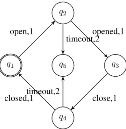
An instance of transition system is shown in Fig. 1. Typically the transition system is used to control a two-state device with error handling, such as valves and pumps. The state with double circles is the initial state. Every transition is associated with a boolean guard followed by a priority number. Smaller number has higher priority. q1 denotes the device is closed, q2 denotes the device is opening, q3 denotes the device is opened, q4 denotes the device is closing, and q5 denotes that some errors have occurred and make the status signals do not arrive in time. The transition system is built as follows. We first define the set of states and the set of lables, then define the transition function, finally use the constructor of TranSys to build a transition system. The result transition system is ValveTransSys. Inductive Valve_Ss : Set :=q1|q2|q3|q4|q5. Inductive Valve_Ls : Set :=
open | opened | timeout | close | closed. Definition Valve_Trans s := match s with | q1 => (open,q2)::nil | q2 => (opened,q3)::(timeout,q5)::nil | q3 => (close,q4)::nil | q4 => (closed,q1)::(timeout,q5)::nil | q5 => nil end.
Definition ValveTransSys := Build_TranSys Valve_Ss Valve_Ls q1 Valve_Trans.
q1 q5 q2 q3 q4 open,1 opened,1 timeout,2 close,1 timeout,2 closed,1
Fig. 1. The transition system of a two-state device with error handling
has a parameter of type TranSys. It associates a boolean variable with each state and label in the transition system using functions Ss and Ls. Specifications InitCondition and Next are deployed to describe the initial and transition constraints respectively. The fields of a record are accessed by the dot operator. By applying GenTs to ValveTransSys, we obtain the specification for the transition system shown in Fig. 1.
Record GenTS (ts : TranSys) := { Ss : ts.(States) -> BVar; Ls : ts.(Labels) -> BVar; InitCondition : ... Next : ...
}
Variable imp : GenTs ValveTransSys.
2) Compound Components: Compound components are com-posed of several connected subcomponents. They are specified using Recordin a similar way as atomic components. One thing needs dis-cussion is how to construct a compound component instance from its subcomponents instances. Suppose we have a compound component specification P and its subcomponents specifications P1 and P2. The construction process is modeled by a function of type Parameters -> P1 -> P2 -> Connections -> P. The function is ap-plied to instances of P1 and P2 and the connections between them to get an instance of P. Connections and Parameters are only for denotational purpose; they are not real types in Coq. Parametersis the parameters of P1, P2 and P3. We define two types of connections. One is eq_same (denoted by infix operator [=]) expressing two variables are connected without delay. The other is eq_one_unit_delay (denoted by infix operator [=1]) expressing two variables are connected with one scan cycle delay. Which type to choose depends on the execution order of components (with respect to the control flow or data flow). For an output variable a and an input variable b (belonging to components A and B respectively), if A is executed prior to B then we have a[=]b; otherwise, we have a[=1]b.
Definition eq_same(v1 v2 : BVar) := forall i, v1 i = v2 i.
Definition eq_one_unit_delay(v1 v2 : BVar) := forall i, v1 i = v2 (i + 1).
Take a square-wave generator for example. The generator has three ports, EN for starting the wave, T for setting the waves’ lengths and Q1 for the output. When EN is 1, then it generates a square wave of length T . The Specification is as follows. WaveGen has one parameter.
Record WaveGen (T : Time) := { wg_EN : BVar; wg_Q : BVar; wg_spec : ...
}
A square-wave generator can be built from a RS-flipflop and a TON-timer. Function Gen_WaveGen demonstrates the construction process. It takes a time, which is the parameter of the wave generator and the parameter of the inner timer, a TON-timer, a RS-flipflop and the inner connections between them, and outputs a wave-generator of the desired length. This function can be defined directly, or built from interactive proof. We choose the second one, since it is more convenient to us.
Definition Gen_WaveGen : forall (T : Time) (timer : TONTimer T)(rs : RSflipflop),
(rs.(rsff_R) [=] timer.(tont_Q _)) /\ (rs.(rsff_Q) [=1] [1] timer.(tont_IN _))
-> WaveGen T.
3) Additional Specifications and Tactics: When specifying components, besides the standard specifications, additional properties are collected as well. These properties are organized as theorems and they are proved based on the standard specifications. For ex-ample, the specification of a transition system should satisfy that at any moment, there is exactly one state variable that is true. This property is described by theorem StateOK. The theorem is general. When applid to a specific component, a specific theorem for the component is obtained. For instance, given imp of type GenTS ValveTransSys, (StateOK _ imp) denotes that if two state variables of imp are true then they are equal.
Theorem StateOK:
forall (ts : TranSys) (imp : GenTS ts), forall (n:nat) (s s’:ts.(States)),
imp.(Ss _) s n = true /\
imp.(Ss _) s’ n = true -> s = s’.
Furthermore, a set of proof tactics could be defined for a com-ponent. For example a set of tactics are developed for GenTS to help prove properties of the generated specification. Theorem TransQ2Q3describes that the system’s current state is q2, if guard timeout is true and opened is false, then the next system’s state will be q3. Proving such a theorem in the framework described in [4] takes tens of lines, while in this framework it only takes one single tactic.
Theorem TransQ2Q3 :
forall n, imp.(Ss _) q1 n = true /\ imp.(Ls _) timeout n = true /\ imp.(Ls _) opened n = false -> imp.(Ss _) q3 (n+1) = true.
To summer up, a component is modeled by a Record type in Coq, accompanied with a set of additional properties and a set of help proof tactics.
III. MODULARVERIFICATION
Properties are stated as theorems to prove. Theorems can be written either in a specific logic, such as LTL and CTL, or in an ad-hoc manner. We choose the latter in the paper.3
A. Specification of the Environment
The environment can be regarded as a special component, thus can be specified by Record as well. Specification of environment is another way to call the constraint over the environment. The
3We have developed a library for LTL. Formulae in LTL are lengthy and
not obvious. How to use LTL to specify properties is not the focus of the paper.
constraints can be divided into two categories: one applies to the whole system and the other applies only to a specific property. The former one can be stated as a hypothesis in Coq. Since we use the section mechanism to model the system, when we close a section, all proved properties (i.e. theorems) are automatically added with the hypothesis.
Informally, the main properties under investigation are statements of the forms that, if a proper sequence of stimuli is received by the PLC system, then some expected outcomes will be observed. The proper sequence of stimuli is the constraint on the environment (i.e. the second type of constraint) for a specific property. It can be expressed by Record types as well.
B. Local Verification
One advantage of modular modeling is that we can verify proper-ties locally. In the dock control system, suppose we have a compo-nent valve1 of type GenTs ValveTransSys and two outputs v1_openand v1_open connecting to valve1.(Ss _) q2 and valve1.(Ss _) q4respectively, which means when valve1 is at state q2 (q4, resp.) an open (close, resp.) signal is set to true. Theorem Valve1OCOK states that the open and close signals can not be set to true at the same time.
Theorem Valve1OCOK :
forall n, ˜(v1_open n = true/\ v1_close n = true).
Since v1_open[=]valve1.(Ss _) q2 and v1_close[=]valve1.(Ss _) q4, Valve1OCOK can be converted to the following goal using rewrite4.
forall n, ˜ (valve1.(Ss _) q2 n = true /\ valve1.(Ss _) q4 n = true).
And this can be proved by only one tactic we design for GenTs (section II-B3).
C. Decomposition Verification
Decomposition verification is realized by embedded proof rules in the system. All the rules are stated as theorems. Theorems are of the form:
M1→ P1
M2→ P2
M1∧ M2→ P
M1, P1, M2, P2and P represent the first component, the property of
the first component, the second component, the property of the second component, the property the composite component needs to prove respectively. They are all predicates over traces. Thus the composition of components are simply the conjunction of their predicates. Using this rule, the problem of proving a property of a composite system is reduced to a set of relatively smaller problems.
We have embedded LTL in our system. Thus properties can be written in LTL. We also developed a library for LTL in which traditional properties of LTL formulae are stated as theorems and proved.
IV. RELATEDWORKS
Though a lot of works have been done aiming at the formal verification of PLC programs [5][6][7], only a few works concentrate on the modular and parameterized aspects of PLC systems.
Compared to our method, [8][9][10] target the source code level modeling and verification. The programming language they consider are Function Blocks (FB) and Sequential Function Charts (SFC). In their verification framework, a subset of structure text (ST) is embedded in the theorem proving system HOL.
4Using Setoid library, we have developed a library which enhances the
rewritetactic to support variables that are equal according to [=].
In [11], a lot of aspects and cases studies about the modular modeling and verification of PLC are discussed. To some degree, they focus on the design phrase, for the specification language they use is Condition/Event systems (in other words, they do not target the source codes). Model checker SMV is used to do the verification based on a translation from C/E system to SMV. Hence, the data types supported are boolean and bounded integer.
Paper [12] is close to our work except that the specification language they choose is TLA+.
V. CONCLUDINGREMARKS
Programmable logic controllers (PLCs) are used extensively in the field of automation. They are getting more complex. Modular development is deployed to solve this problem. Besides the benefits it brings to the software development, it also helps the formal specification and verification of PLC systems. In this paper, we propose a method to do modular and parameterized specification and verification of PLC systems in the theorem proving system Coq. Record type is used to specify the components. Both atomic and compound components of PLCs are dealt in a similar way. Besides them, a kind of specification generators is proposed and realized using Recordas well. The process of constructing a compound component from several subcomponents is modeled by a function, which builds a link between the implementation and the specification. Various related aspects are discussed and demonstrated via examples.
REFERENCES
[1] Y. Bertot and P. Cast´eran, Interactive Theorem Proving and Program De-velopment Coq’Art: The Calculus of Inductive Constructions. Springer, 2004.
[2] IEC International Standard 1131-3, Programmable Controllers, Part 3: Programming Languages, 1993.
[3] H. Zhang, S. Merz, and M. Gu, “Specifying and Verifying PLC Systems with TLA+,” in Proceedings of the 2009 Third IEEE International Symposium on Theoretical Aspects of Software Engineering-Volume 00. IEEE Computer Society, 2009, pp. 293–294.
[4] H. Wan, G. Chen, X. Song, and M. Gu, “Formalization and verification of PLC timers in Coq,” in COMPSAC 2009: The 33rd Annual IEEE International Computer Software and Applications Conference, 2009. [5] A. Mader, “A classification of PLC models and applications,” in In
WODES 2000: 5th Workshop on Discrete Event Systems. Kluwer Academic Publishers, 2000, pp. 21–23.
[6] G. Frey and L. Litz, “Formal methods in PLC programming,” in IEEE International Conference On System Man and Cybernetics, vol. 4, 2000, pp. 2431–2436.
[7] M. Younis and G. Frey, “Formalization of existing PLC programs: A survey,” in Proceedings of CESA, 2003, pp. 0234–0239.
[8] N. V¨oker and B. J. Kr¨aer, “Automated verification of function block-based industrial control systems,” Science of Computer Programming, vol. 42, no. 1, pp. 101 – 113, 2002.
[9] ——, “Modular verification of function block based industrial control systems,” in The 24th IFAC/IFIP Workshop on Real Time Programming (WRTP’99), Saarland, Germany, 30 May - 3 June 1999, 1999. [10] B. J. Kr¨amer and N. V¨olker, “A highly dependable computing
architec-ture for safety-critical control applications,” Real-Time Systems, vol. 13, no. 3, pp. 237–251, 1997.
[11] B. Lukoschus, “Compositional verification of industrial control sys-tems, methods and case studies,” Ph.D. dissertation, Christian-Albrechts-Universit¨at zu Kiel, 2005.
[12] A. Wolpers and W. Stephan, “Modular verification of programmable logic controllers with TLA,” in INCOM ’98 Workshop on Formal verifi-cation for Automation Engineering, G. Model and ois B. Vernadat Franc, Eds., 1998, pp. 121–126.
![[PDF] Débuter avec la réalisation d’application web dynamiques ASP | Cours informatique](data:image/gif;base64,R0lGODlhAQABAIAAAP///wAAACH5BAEAAAAALAAAAAABAAEAAAICRAEAOw==)