Avionics Systems Design for Cooperative
Unmanned Air and Ground Vehicles
by
Alexander Omelchenko
Submitted to the Department of Aeronautics and Astronautics in partial fulfillment of the requirements for the degrees of
Master of Science in Aeronautics and Astronautics and
Engineer in Aeronautics and Astronautics at the
MASSACHUSETTS INSTITUTE OF TECHNOLOGY
June 2004
@ Massachusetts Institute of Technology. All right reserved.
Author ...
Department o ron#ics and Astronautics May 14, 2004
A
C ertified by ...
John J. Deyst Professor of Aeronautics and Astronautics Thesis Supervisor Certified by ...
Manuel Mafinez-Sanchez Professor of Aeronautics and Astronautics Chairman, Engineer in Aeronautics and Astronautics Program Accepted by ...
Eward M. Greitzer
H.N. Slater Professor of Aeronautics and Astronautics
MASSACHUSETTS INS OF TECHNOLOGY
JUIL
O 12004
LIBRARIES
-Avionics Systems Design for Cooperative
Unmanned Air and Ground Vehicles
by
Alexander Omelchenko
Submitted to the Department of Aeronautics and Astronautics on May 14, 2004, in partial fulfillment of the requirements
for the degrees of
Master of Science in Aeronautics and Astronautics and
Engineer in Aeronautics and Astronautics
Abstract
This thesis summarizes the results of the design of avionics systems intended for use onboard unmanned air and ground vehicles, that are parts of a multi-vehicle system whose primary mission objective is to provide up-close surveillance capability from a large stand-off distance. Different types of cooperative action between air and ground vehicles, that can help to enhance the overall system surveillance capability, are analyzed, including communication relay, simultaneous visual surveillance of ground objects from air and ground vehicles, and visual coverage of ground vehicles from air vehicles. Both hardware and software design as well as practical implementation of the designed avionics systems are discussed, and results of field tests are presented.
Thesis Supervisor: John J. Deyst
Table of Contents
Table of Contents ... 5 List of Figures ... 7 List of Acronyms ... 9 Acknowledgements ... 11 1. Introduction ... 131.1 Background and M otivation ... 13
1.2 Parent/Child UAV Project ... 14
1.3 MDTPP Project ... 16
1.4 Thesis Overview ... 17
2. Cooperative Surveillance in the PCUAV System ... 19
2.1 Mission Analysis ... 19
2.2 Mini Vehicle Avionics System ... 20
2.3 First Tier Vehicle Simulator ... 26
2.4 Laptop Ground Station ... 28
2.5 Software Architecture ... 29
2.6 Flight Tests ... 32
2.7 Chapter Summary and Conclusions ... 40
3. Cooperative Surveillance in the MDTPP System ... 44
3.1 MDTPP Goals and Mission Analysis ... 44
3.2 Ground Vehicle and Air Vehicle Cooperation in the MDTPP System ... 46
3.3 Testbed Ground Rover ... 47
3.4 Testbed Aircraft ... 58
3.5 Integrated Camera Platform ... 60
3.6 Testbed Aircraft Avionics System ... 67
3.7 Approach for Camera Pointing Control ... 71
3.7.2 Accurate Camera Pointing ... 72
3.8 Hybrid System: Rover with Personal Tethered Flyer ... 74
3.9 Chapter Summary and Conclusions ... 82
4. Conclusions ... 86
Appendix A PCUAV Air Vehicles ... 89
Appendix B Link Equation ... 91
Appendix C MPEG Video Compression ... 93
List of Figures
Figure Figure Figure Figure Figure Figure Figure Figure 1-1 2-1 2-2 2-3 2-4 2-5 2-6 2-7 Figure 2-8 Figure 2-9 Figure 2-10 Figure 2-11 Figure 2-12 Figure 2-13 Figure 2-14 Figure 3-1 Figure 3-2 Figure 3-3 Figure 3-4 Figure 3-5 Figure 3-6 Figure 3-7 Figure 3-8 Figure 3-9 PCUAV concept ...M ini vehicle avionics architecture ... Mini vehicle avionics computer ... First tier vehicle simulator architecture ... First tier vehicle simulator ... Laptop ground station ...
Software architecture for single video source ...
Software architecture for two video sources with camera control and retransm ission via aircraft ...
First flight test scenario ...
Snapshot of GUI showing an image from the first flight test ... Second flight test scenario ... 34
Camera motion control from laptop ... Sample images from the second flight test ... Third flight test scenario ...
Snapshot of GUI from the third flight test ... Testbed ground rover avionics architecture ... Testbed ground rover ...
Laptop ground station with modified R/C console ... M odified R/C console ...
Testbed ground rover graphical user interface ... "Software joystick" ...
Testbed ground rover remote control with
retransm ission via aircraft ... Image return from testbed ground rover with retransm ission via aircraft ...
Mission scenario with rover/aircraft cooperation ...
15 22 24 26 27 28 29 30 32 33 35 36 37 39 49 50 51 52 53 54 56 57 58
Figure Figure Figure Figure Figure Figure Figure Figure Figure Figure Figure Figure Figure Figure Figure Figure
Figure 3-26 Using down-looking camera for flyer attitude control ... 80
3-10 3-11 3-12 3-13 3-14 3-15 3-16 3-17 3-18 3-19 3-20 3-21 3-22 3-23 3-24 3-25 Testbed aircraft ... 59
High zoom/pan/tilt camera ... 60
High zoom camera inside flight box ... 61
Integrated camera platform assembled ... 62
Integrated camera platform installed onboard testbed aircraft ... 63
Snapshot of GUI showing an image from the flight test ... 65
Snapshot of GUI showing an image from the flight test ... 66
Testbed aircraft avionics architecture ... 67
Low zoom/internal pan/tilt camera ... 70
Coarse camera pointing ... 71
Accurate camera pointing ... 72
Principle of visual tracking ... 73
Rover with personal tethered flyer concept ... 75
Applications of the hybrid system ... 76
Hovercraft type flyer details ... 78
List of Acronyms
bpp bits per pixel bps bits per second B&W Black and White
CIF Common Intermediate Format
CPU Central Processing Unit dB Decibel
DC Direct Current
DGPS Differential Global Positioning System
DI Digital input
DO Digital output FOV Field Of View
fps frames per second
GPS Global Positioning System
GUI Graphical User Interface
IDE Integrated Drive Electronics
IP Internet Protocol
JPEG Joint Photographic Experts Group
LOS Line of Sight
MAV Micro Unmanned Aerial Vehicle Mbps Megabits per second
MDTPP MIT/Draper Technology Partnership Project MIT Massachusetts Institute of Technology
MPEG Moving Picture Experts Group
NTSC National Television System Committee
PC Personal Computer
PCUAV Parent/Child Unmanned Aerial Vehicle
PDV Payload Delivery Vehicle
PWM Pulse Width Modulation
R/C Remote Control
RGB Red Green Blue
RTP Real Time Protocol
Tcl Tool Command Language
TCP Transmission Control Protocol
UAV Unmanned Aerial Vehicle
UDP User Datagram Protocol
UGV Unmanned Ground Vehicle
Acknowledgements
The work described in this thesis was made possible through the support from the
C. S. Draper Laboratory.
I would like to thank my advisor, Professor John Deyst, and Dr. Brent Appleby
for giving me the opportunity to participate in these projects.
I would like to thank Professor John Chapin for his advisement during the early
days of the PCUAV project.
I appreciate all the comments I received from Sean George, John Deyst, and Brent Appleby during the writing of this thesis.
My special thanks to Jan Meyer who has always been a very supportive roommate
and friend.
It has been a great experience to work in this multi-national team with students from different countries covering probably half the globe, and I would like to thank all the students who helped to create this very special working environment.
Chapter 1
Introduction
1.1 Background and Motivation
Unmanned Aerial Vehicles (UAV) and Unmanned Ground Vehicles (UGV) find numerous applications as surveillance agents capable of penetrating different areas where human presence is either undesired, dangerous, or impossible. While individual surveillance agents can provide the desired surveillance capability in most simple scenarios, such as visual inspection of a ground object from either air or ground, their use becomes very limited as operating conditions become more complicated. One major limitation is the operational range. If surveillance capability is desired at a distant site, main issues become the delivery of the surveillance system to the site and the communication range of the system, as well as the maintaining of line-of-sight (LOS) between a ground operator and the system. If, in addition, mission objectives include simultaneous surveillance of multiple ground objects, some of which may not be directly observable from the air, such missions become impossible to accomplish with any single-vehicle system. Overall surveillance capability can be significantly enhanced by the use of systems of cooperative vehicles. Simultaneous use of multiple surveillance vehicles allows the achievement of all of these objectives as well as the extension of system
capabilities to include some new ones, such as visual tracking with geolocation of stationary or moving ground objects. All of these issues are addressed in the Parent/Child
UAV system.
1.2 Parent/Child UAV Project
Having realized the importance of cooperative multi-vehicle systems for unmanned surveillance missions, Draper Laboratory, in cooperation with the Department of Aeronautics and Astronautics at MIT, initiated a research project in 1998 that had the goal of the design and development of a cooperative system of UAVs to enable up-close surveillance capabilities from a large stand-off distance. The project was given a name of Parent/Child UAV (PCUAV).
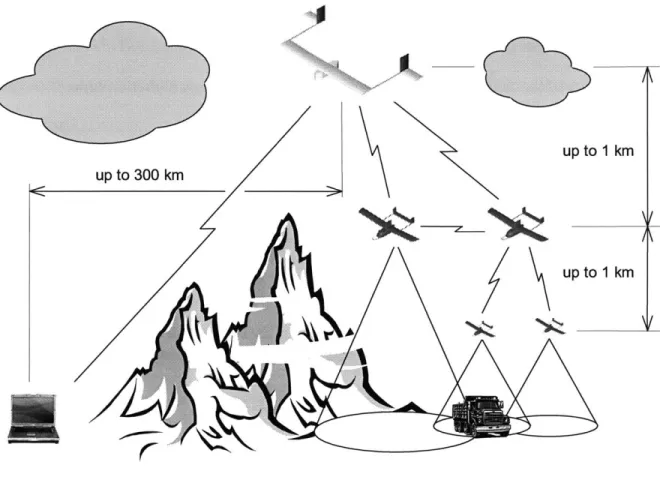
The general concept of the PCUAV system is depicted in Figure 1-1. The system includes a medium-size UAV (3 to 4 meters wingspan) called "parent vehicle", two smaller UAVs (up to 1 meter wingspan) called "mini-vehicles", and may include a number of micro-UAVs (MAV), ground rovers, and ground sensors. The parent vehicle provides transportation capability to deliver the whole system of vehicles to a mission site and long-range communication capability to enable data exchange between the mission site and a distant ground station. During the cruise to the mission site, the mini-vehicles are attached to the fuselage of the parent vehicle, while micro-mini-vehicles and ground sensors are contained inside payload delivery vehicles (PDV) inside the cargo bay of the parent vehicle. Upon arrival to the mission site, the mini-vehicles are deployed and begin to loiter above the mission site according to their personal flight schedules to achieve their part of the mission objectives. Micro-vehicles and ground sensors are then deployed and delivered to low altitude or the ground by payload delivery vehicles. All
micro vehicles, PDVs, and ground sensors are considered expendable, while mini-vehicles, after the completion of their missions, reintegrate with the parent vehicle and return with the parent vehicle to the launch site. Detailed review of the rendezvous and reintegration techniques utilized by the parent and the mini vehicles can be found in [1] and [2].
up to 1 km
up to 1 km
N
'I
Figure 1-1: PCUAV concept
Once deployed, the whole system can be viewed as a three-tier system, the micro vehicles and ground sensors being the first tier, the mini-vehicles being the second tier,
and the parent vehicle being the third tier of the system. The main objective of micro-UAVs is to provide up-close visual surveillance of different objects of interest on the ground. The advantage of using micro-UAVs is their ability to approach ground objects to provide visual information not obtainable from higher altitude UAVs, but, at the same time, they are very limited in communication range. Therefore, the presence of the second tier of the system is essential for their successful operation. Mini vehicles, that constitute the second tier, have two main roles in the system: they provide visual surveillance from medium altitudes and provide communication relay between vehicles and sensors of the first tier and the parent vehicle that loiters at a higher altitude.
Due to its multi-vehicle and multi-tier nature, the PCUAV system is capable of providing surveillance capabilities unattainable with any single-vehicle surveillance system.
1.3 MDTPP Project
After the completion of the PCUAV project in 2002, a second project was jointly initiated by the Draper Laboratory and the Department of Aeronautics and Astronautics at MIT. The project was given a name of MIT/Draper Technology Partnership Project (MDTPP).
In part as an extension of capabilities of the PCUAV project, the MDTPP project is focused on accurate deployment and operation of a distributed ground sensor network from a UAV of Predator class. The sensor network can include large numbers of stationary and mobile ground nodes to provide surveillance capability at a remote site. One part of the project is the investigation of the possibilities of cooperation between unmanned ground and air vehicles to enhance aggregate surveillance capability.
1.4 Thesis Overview
This thesis summarizes the results of the design and development of avionics systems for unmanned air and ground vehicles used in the PCUAV and MDTPP projects, whose primary goal is to provide visual surveillance capability in a cooperative multi-vehicle system.
The thesis consists of two main parts: Chapter 2 describes the design and implementation of avionics systems used in the PCUAV project, and Chapter 3 describes the design and implementation of avionics systems used in the MDTPP project.
First, Chapter 2 describes avionics system used onboard the mini vehicles of the
PCUAV system for visual surveillance and communication relay between the vehicles of
the first tier of the PCUAV system and the parent vehicle. Then the avionics system of a first tier vehicle simulator is described, followed by the discussion of experimental results obtained during a series of flight tests in which both the mini vehicle and the first tier vehicle simulator are used for cooperative visual surveillance.
Chapter 3 begins with the detailed review of the objectives of the MDTPP project and the role of mobile ground nodes in the distributed ground sensor network. Design and implementation of a testbed ground rover that simulates a mobile ground node is then described, followed by a discussion of different types of cooperative action between mobile ground nodes and air vehicles that are relevant to the MDTPP project, which include communication relay and visual coverage of mobile ground nodes from air vehicles. Next, a testbed aircraft and an integrated camera platform built for use onboard the aircraft are described, including the results of a test of the integrated camera platform in flight conditions. After that a detailed design of the avionics system for the testbed
aircraft is discussed whose main objectives are to enable cooperative action between the aircraft and the testbed ground rover, and to provide general-purpose visual surveillance capability. Chapter 3 concludes with a conceptual design of a hybrid system that combines the advantages of small UAVs and small UGVs in a single system.
Chapter 2
Cooperative Surveillance in the PCUAV
System
In this chapter a typical PCUAV surveillance mission is analyzed to derive the requirements for the design of the avionics system for a mini vehicle, whose mission objectives are visual surveillance and communication relay. Mini vehicle avionics system design and implementation are then discussed. Results of flight tests with both a single video source and two video sources are discussed.
2.1 Mission Analysis
In a typical PCUAV surveillance mission, mini vehicles, that constitute the second tier of the PCUAV system, have two main roles: providing visual surveillance from medium altitudes (up to 1 km) and providing communication relay between the first tier of the system and the parent vehicle, that loiters at a higher altitude.
Specific requirements for a video subsystem include collecting high quality visual information about regions of interest on the ground from a small, relatively unstable air vehicle in the presence of high frequency vehicle vibrations induced by the vehicle propulsion device. To enable geolocation of the observed ground objects from the
obtained visual information, the avionics system should be capable of measuring vehicle attitude and position with respect to a global coordinate frame.
The communication subsystem should be capable of providing a transparent communication interface to enable data exchange between the vehicles/sensors of the first tier and the parent vehicle.
In a multi-vehicle surveillance system, such as the PCUAV system, one important capability that should be enabled is the ease of access by operators to visual information from any of the vehicles, which becomes an additional requirement for the design of the communication subsystem.
2.2
Mini Vehicle Avionics System
As a solution to the problem of providing visual surveillance capability from a relatively unstable air vehicle in the presence of vehicle vibrations, a video subsystem was designed to provide a sequence of still digital images rather than a continuous video stream. The quality of a continuous video stream would suffer in this case because of vehicle instabilities, a streaming video picture would look shaking, and it would be difficult for an operator to follow rapidly changing details in the field of view. Still digital images, taken sequentially at discrete moments of time, are free from these limitations, and give the operator some time to pay attention to different details in every image. Assuming two mini vehicles in the PCUAV system, the frame rate of the sequence of still digital images was chosen to be one frame per second per mini vehicle.
The most reasonable choice of communication medium to meet the stated communication subsystem requirements is a wireless computer network based on Internet Protocol (IP). In an IP network, every vehicle is assigned a unique IP-address. Visual
information in digital format can be easily routed to reach any destination point or multiple points in the network, which allows any number of operators to get access to visual data from any of the vehicles in the system. IP network also allows an operator to remotely log into any vehicle's computer for command/control while maintaining
security of the connection if necessary.
A combination of digital video and digital communications allows realization of
high video quality at the ground station. A specific feature of this design solution, as was mentioned above, is the use of a sequence of still digital images, which makes the use of Transmission Control Protocol (TCP) possible. Usually, to transmit a continuous video stream via an IP network a fast protocol, such as User Datagram Protocol (UDP), is used. However, the UDP protocol, though fast, is not reliable. The TCP protocol is slower, but provides reliable communications, with guaranteed delivery of every packet. The reliability of the TCP protocol is achieved via the use of an acknowledgement mechanism: the delivery of every packet is acknowledged from the receiver, signaling that a next packet can be sent; if a packet's delivery was not acknowledged, the packet will be sent again. This mechanism ensures the delivery of every packet but creates an additional communication overhead, compared to the UDP protocol, which does not use the acknowledgement mechanism. As the frame rate in this design solution is not high, using the TCP protocol is appropriate and avoids the loss of visual information.
For practical implementation, IEEE 802.1 lb compliant wireless local area network (WLAN) communication devices were used in the avionics system, because these devices are commercially available and allow the creation of a wireless computer network at a reasonable price, while simulating full communication functionality of the objective system. TCP/IP was used as the communication protocol for both
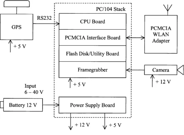
command/control and image return. The mini vehicle avionics architecture is shown in Figure 2-1.
The central part of the avionics system is a PC/104 computer stack that includes
CPU board, utility board with the usual set of PC computer interfaces (including floppy
drive interface and IDE interface) and a storage device (IDE flash disk), framegrabber board, PCMCIA interface board, and power supply board that provides power to the computer stack as well as to other electronic components in the system. Using a flash disk, rather than a mechanical hard drive, is essential in the presence of high frequency vibrations and noise induced by a propulsion device, such as a piston engine. It was found during ground tests of the system that mechanical hard drives often fail in such conditions.
PC/104 Stack CPU Board
GPS
I PCMCIA Interface Board
+ 5
Flash Disk/Utility Board Framegrabber Input + 5 V
6-40V
Battery 12 V Power Supply Board . . .... .... .---... ..
PCMCIA WLAN
Adapter
+ 12V
A Global Positioning System (GPS) receiver is included in the system in order to
measure GPS coordinates of the points from which images are taken, which, in combination with the vehicle attitude measurements, provide a set of information that can be used to geolocate observed ground objects. In this work, it is assumed that the vehicle attitude information is available from the inertial sensors of the flight control subsystem (mini-vehicle flight control is not a part of this thesis, more details on mini-vehicle flight control can be found in [1] and [2]).
Cisco Aironet PC4500 WLAN PCMCIA cards (pc-cards) in combination with
2.2 dB antennas are used for communications in both the avionics system and the laptop
ground station. Aironet pc-cards are based on the Harris Semiconductor's PRISM digital communication chipset, and, among all the considered WLAN pc-cards, they allowed for the longest communication range. These pc-cards performed extremely well and allowed communication range of the order of 1 kilometer to be achieved between the flying airplane and the ground station.
An analog NTSC video-camera provides an analog video stream at 30 frames per second (fps), at a resolution of 640x480 pixels. For many surveillance purposes, black and white (B&W) images have sufficiently high quality. B&W images with 255 levels of gray, 8 bits per pixel (bpp) encoding, are used in this design solution. The main reason for using B&W images is to reduce the required communication bandwidth. Given the limitations of a power source onboard a small air vehicle, minimizing the required data rate is essential in order to increase communication range. Compared with color images, using B&W images significantly reduces the required communication bandwidth. For comparison, a B&W image with 8 bpp has three times smaller size than a color image of the same resolution with common Red/Green/Blue (RGB) color scheme with 24 bpp (one
byte for each color). It should be noted that solving the problem of increased range by pure increase of antenna gain is impractical in this case, because increasing antenna gain leads to the increased directivity of the antenna, whereas for this type of application directivity of antennas should be as low as possible.
The video output of the camera is connected to the framegrabber board, which captures still digital images at discrete moments of time, with a frame rate of 0.5 frame per second (fps), or one frame every two seconds. The images are then compressed using a JPEG algorithm. JPEG compression ratios of up to 15:1 produced image compression with no visible loss of image quality. Higher compression ratios resulted in visible image quality degradation.
The compression ratio of 15:1 was therefore chosen as the operational compression ratio used in the system. Compressed images are transmitted over WLAN link to the laptop ground station and shown in real time on the screen of the ground station.
The assembled computer stack is shown in Figure 2-2. The computer stack is enclosed inside an aluminum box that serves two purposes: protect the computer stack in case of airplane crash and shield electromagnetic radiation from inside the stack, as it was found that some electronic components, in particular GPS antenna and R/C receiver, are very sensitive to electromagnetic interference from the computer. When installed inside the airplane, the computer box is enclosed inside vibration isolation medium.
The Linux operating system was chosen for both the avionics computer and the laptop ground station. Linux is a Unix-like operating system that can be used on PC platforms and has all important Unix features including true multi-tasking and direct
2.3 First Tier Vehicle Simulator
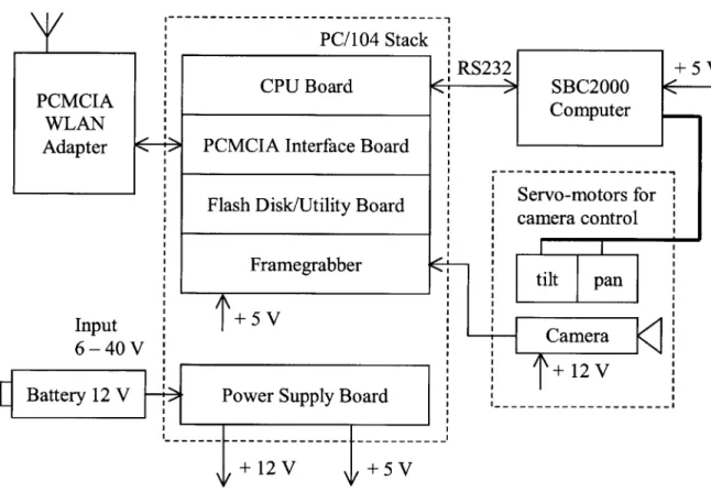
The purpose of the first tier vehicle simulator, also referred to as ground video system, is to simulate visual surveillance and communication capabilities of any of the vehicles of the first tier of the PCUAV system. The architecture of the simulator is shown in Figure
2-3. PCMCIA WLAN Adapter PC/104 Stack RS232 + 5 V CPU Board
>
SBC2000 Computer_PCMCIA Interface Board
Flash Disk/Utility Board
camera control
Framegrabber
+ 5 V
Camera + 12 V Power Supply Board
---
t---Figure 2-3: First tier vehicle simulator architecture
The architecture is similar to that of the mini vehicle, except that the GPS receiver is not included. An additional component is a single-board SBC2000 computer that communicates with the main computer via an RS232 serial port and controls two servo-motors used for pan and tilt motion of the camera. An operator has the ability to control
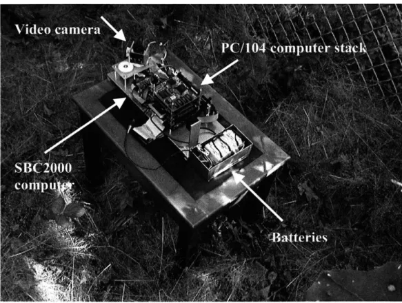
the motion of the camera remotely to point the camera in different directions using video information from the camera as feedback. All communications between the simulator and the operator are done via the mini vehicle to validate the mini vehicle's communication relay capability. Figure 2-4 shows the simulator positioned in a forest during one of the flight tests.
2.4
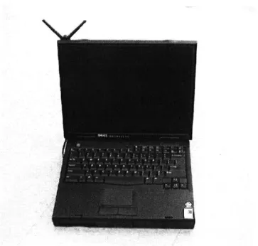
Laptop Ground Station
A Dell Inspiron 7500 laptop computer, shown in Figure 2-5, was used as a ground station. A communication antenna can be seen attached at the top left corner of the computer screen. The antenna is connected to a WLAN communication pc-card installed inside one of the computer's pc-slots. The same kind of antenna is used in the avionics system onboard the mini vehicle and in the first tier vehicle simulator. The antenna has 2.2 dB gain and directivity pattern very close to omni-directional. It is essential for this type of application that communication antennas be as close to omni-directional as possible so as to enable communications between all vehicles in the system, for any orientation of the vehicles.
Figure 2-5: Laptop ground station
user interfaces (GUI) have been developed for viewing real time images arriving at the ground station from different vehicles.
2.5
Software Architecture
A number of software modules have been developed that can be used in different combinations depending on what flight test they are being used for. The software architecture for a flight test with a single video source onboard the mini vehicle is shown in Figure 2-6.
Mini vehicle IP: 192.168.1.8
Image
--...
L-
JPEG capture compression Analog NTSC video-camera Server 1 SequenceFI
of still digitalFIi
images ... @ 0.5 fps F-Laptop IP: 192.168.1.6 Client 1 GUIshowing images Hard drive
Mini vehicle IP: 192.168.1.8
Image
I--
.. JPEGcapture compression Analog NTSC video-camera Server 1 Server 2 Server 3
FII
FLI
WLANClient 1 Client 2 Client 3
Hard drive
GUI GUI Operator camera showing images contrl
control input Laptop IP: 192.168.1.6 .... _ .. ___.. .. _ . .. _ _. _ ._--- -- --- -- ----Client 4 Client 5 Camera JPEG motion compression control A Image capture Analog NTSC pan/tilt video-camera
Ground video system IP: 192.168.1.7
L ..- _ .. . _ . ._- .... . . . .. . ... _- _ .. _ ... _- _ ... _ ...
Figure 2-7: Software architecture for two video sources with camera control and
The system operates as follows. Digital images are captured from an analog video stream, compressed using a JPEG algorithm, and sent to the server 1 program. Server 1 maintains a communication link with client 1 in the laptop and sends compressed images to client 1. Client 1 stores the received images in the laptop's hard drive, while the GUI displays the arriving images in real time on the screen of the laptop.
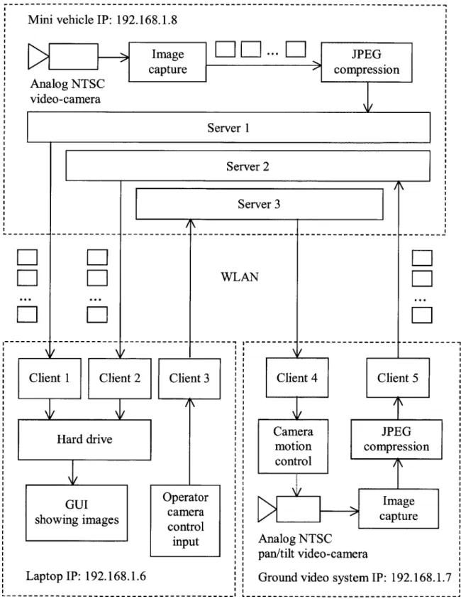
Figure 2-7 shows the software architecture for a flight test with one video source onboard the mini vehicle, one video source in the ground video system (first tier vehicle simulator), with remote control of the pan/tilt video-camera in the ground video system from the laptop ground station, and with all communication traffic retransmitted via the mini vehicle. The architecture includes multiple server/client groups in order to enable concurrent execution of communication tasks. Multiple ports can be defined at the same IP interface, which allows several communication programs to share the same IP address while using different port numbers. The pair of server 1 and client 1 in this architecture performs the same tasks as in the previous architecture: sending visual information collected from the mini vehicle to the ground station. Servers 2 and 3 in the mini vehicle are responsible for retransmission of communication traffic between the first tier vehicle simulator and the ground station: images from the simulator are retransmitted by server 2 to the ground station, while camera motion commands are retransmitted by server 3 from the ground station to the simulator. The video subsystem used in the simulator is similar to that used in the mini vehicle, and its operation is programmed in a similar set of software modules. The GUI used in the laptop in this architecture is different from the one used in the previous architecture as it simultaneously displays images arriving from two vehicles.
2.6 Flight Tests
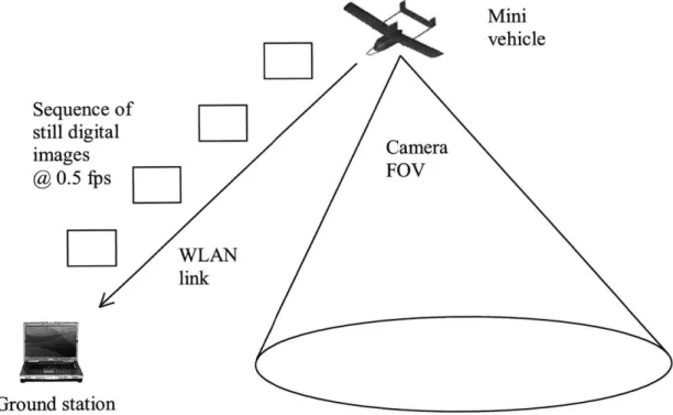
A series of flight tests were conducted to validate the designed avionics systems. The first
flight test investigated the scenario of a single mini vehicle with single video source installed onboard the vehicle. This scenario is depicted in Figure 2-8.
D
Sequence of still digital images @ 0.5fps[
Ground stationz
Mini vehicleEl'
FOV WLAN linkFigure 2-8: First flight test scenario
As a testbed for surveillance flights, a remotely controlled model of the mini vehicle was used. The airplane was flown by a pilot along an arbitrary trajectory, while the onboard avionics system was collecting visual information and sending it over a WLAN
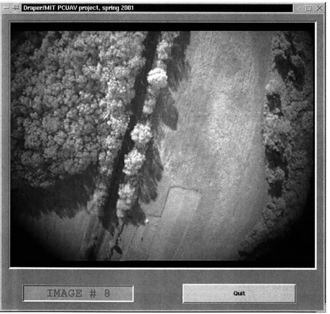
communication link down to the laptop ground station. The arriving images were displayed in real time in a graphical user interface (GUI) on the screen of the ground station. A snapshot of the GUI showing one of the images from the first flight test is
shown in Figure 2-9. The system performed very well during the flight test. Several series of high quality images from the airplane have been recorded. At no point during flight, for any orientation of the vehicle, was the communication link lost or the link quality degradation observed.
Draper/MIT PCUAV project, Spritg 2001
The second flight test had the goal of testing the communication relay capability of the mini vehicle in combination with the first tier vehicle simulator performing visual surveillance on the ground. The scenario of the second flight test is depicted in Figure 2-10. The mini vehicle provided retransmission of all communication traffic between the first tier vehicle simulator (ground video system) and the laptop ground station. Two-way communication traffic included video images from the ground video system sent to the ground station and camera motion commands from the operator of the ground station sent to the ground video system. Thus the operator could remotely control the motion of the camera by issuing commands from the laptop and using visual information from the camera as a feedback.
Mini vehicle
Sequence of
still digital WLAN
images link @ 0.5 fps LJ
LIII
Images Camera motion commandsLIII
LIII
Ground station Ground video system
pan left pan right
Ground station tilt up >
keyboard---tilt down >
Ground video system
Figure 2-11: Camera motion control from laptop
In order to issue camera motion commands from laptop four keys on the laptop keyboard were used, as shown in Figure 2-11. The motion of the camera can be decomposed into four simple motions: pan left, pan right, tilt up, and tilt down, which provides a reasonable correlation with four "arrow" keys on the keyboard. The camera performs one of the four simple motions for as long as the corresponding key is being pressed, and stops when the key is released. Two of the four simple motions (one pan and one tilt) can be used at the same time. The same type of GUI was used for viewing arriving images in the laptop as during the first flight test.
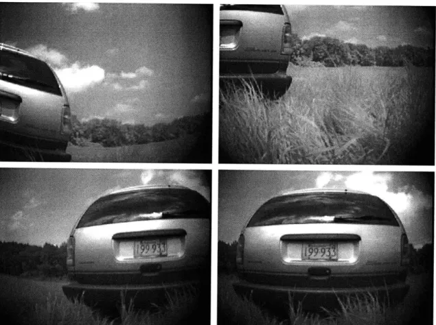
The ground video system was placed next to a van to simulate a situation in which a vehicle of the first tier approaches an object of interest on the ground for visual inspection. Sample images recorded during the second flight test are shown in Figure 2-12. Changes in the content of the images can be seen due to the camera rotation. All systems performed very well during the flight test, and several series of high quality
images from the ground video system have been recorded. At no point during flight, for any orientation of the mini vehicle, was the communication link lost or was the link quality degradation observed.
The scenario of the third flight test is depicted in Figure 2-13. Sequence of still digital images
@
lfps
5
Ground station Images fromground video system
L
Images from mini vehicleFigure 2-13: Third flight test scenario
The purpose of the third flight test was to validate all capabilities of the mini vehicle together, including visual surveillance and communication relay in combination with the first tier vehicle simulator performing visual surveillance on the ground. This scenario closely resembles a typical PCUAV mission scenario, except that in a real mission all
communications between the tier of the mini vehicles and the ground station are done via the parent vehicle in order to achieve much longer communication range. The first tier vehicle simulator was placed on the bank of a river next to a bridge across the river, while the remotely controlled mini vehicle with the avionics system onboard was flying above in circles taking images of the area from the air. All communications between the first tier vehicle simulator and the laptop ground station were done via the flying mini vehicle in the same way as it was done during the second flight test. In addition, visual information from the mini vehicle was transmitted down to the ground station in the same communication link. The graphical user interface written for this flight test is capable of displaying real time images arriving from both vehicles. A snapshot of the GUI showing some of the images recorded during this flight test is shown in Figure 2-14. Two consecutive images from the ground video system are displayed to allow for some history of situation development to be viewed. During the flight test, all systems performed very well, and several series of high quality images from both vehicles have been recorded. At no point during flight, for any orientation of the mini vehicle, was the communication link lost or was the link quality degradation observed.
The summary of the performed flight tests is as follows. The avionics systems designed for the mini vehicle and the first tier vehicle simulator met their requirements and provided the expected visual surveillance and communications capabilities. Their performance was validated in conditions close to operational conditions of a typical
2.7
Chapter Summary and Conclusions
In this chapter, results of the design and development of avionics systems for vehicles in the PCUAV system, whose primary mission objective is to provide visual surveillance capability, were presented.
In Section 2.1, a typical PCUAV surveillance mission was analyzed to derive the requirements for video and communication subsystems of the mini vehicle.
The design of the mini vehicle's avionics hardware was presented in Section 2.2. As a solution to the problem of providing visual surveillance capability from a small relatively unstable air vehicle in the presence of vibrations, the system was designed to provide a sequence of still digital images, taken sequentially at discrete moments of time, rather than a continuous video stream. Monochromatic video in combination with JPEG image compression were used to minimize the required communication bandwidth, which is essential in order to maximize communication range given the limitations of a power source onboard a small air vehicle. The communication capability required of the mini vehicle was defined as providing data relay between the vehicles of the first and the third tiers of the PCUAV system while enabling ease of access by operator(s) to visual data from any of the vehicles. As a solution to the communication problem, a wireless computer network was chosen. For practical implementation, an IEEE 802.1 lb compliant
WLAN ad-hoc network was used for both command/control and image return. In order to
achieve high video quality on the ground station, the TCP/IP communication protocol was used. TCP/IP protocol provides reliable communications with guaranteed delivery of all packets and allows to avoid the loss of visual information.
Section 2.3 presented the design of the avionics system used in the first tier vehicle simulator. The approach used in the design of video and communication
subsystems of the first tier vehicle simulator is similar to that used in the mini vehicle's avionics system.
The laptop ground station was described in Section 2.4.
Section 2.5 presented the design of software architectures used in all vehicles. The software was implemented as a set of modules that can be used in different combinations depending on what types of flight tests they are used for. A server/client approach was used for communications, and multiple server/client groups were used to enable concurrent execution of communication tasks. All software was implemented in C under the Linux operating system. Graphical user interfaces were implemented in Tcl/Tk. The Linux operating system was chosen for use in all vehicles and the ground station. As a Unix-like operating system, Linux has all of the important Unix features including true multi-tasking and direct support of IP protocol.
Flight tests conducted in order to validate the designed avionics systems were presented in Section 2.6. Three main types of the conducted flight test were as follows.
The first flight test had the goal of testing the visual surveillance capability of the mini vehicle. The first flight test scenario involved the mini vehicle flying along arbitrary trajectories while the onboard avionics system was collecting visual data and transmitting it down to the laptop ground station via a WLAN communication link. Arriving images were displayed in real time on the screen of the laptop and saved to the laptop's hard disk.
The goal of the second flight test was to test the communication relay capability of the mini vehicle in combination with the first tier vehicle simulator performing visual
surveillance on the ground. During the second flight test, the mini vehicle flew in roughly circular trajectories above the mission site while the onboard avionics system was doing retransmission of two-way communication traffic between the first tier vehicle simulator and the laptop ground station: video images from the simulator to the ground station and camera motion commands from the ground station to the simulator. The ground station operator had the ability to remotely control the motion of the camera in the first tier vehicle simulator while using visual information from the camera as a feedback.
The third flight test had the goal of testing the combined visual surveillance and communication capability of both the mini vehicle and the first tier vehicle simulator in conditions close to operational conditions of a typical PCUAV surveillance mission. Two video sources were used during the third flight test: one onboard the flying mini vehicle and one in the first tier vehicle simulator on the ground. All communications between the first tier vehicle simulator and the ground station were done via the flying mini vehicle, including camera motion commands and image return. Visual information from both video sources was simultaneously displayed in real time on the screen of the ground station.
Experimental results collected during the flight tests indicate that the designed avionics systems met their requirements and provided the expected visual surveillance and communication capabilities. Several series of high quality images were recorded. The communication range between the flying mini vehicle and the ground station of the order of one kilometer was achieved. At no point during flight was the communication link lost or was the link quality degradation observed, for any orientation of the mini vehicle.
The performed work described in this chapter was a part of a broader effort by a number of people. Other team members investigated other aspects of the PCUAV system,
including vehicle design, vehicle flight control, rendezvous and reintegration techniques. More details on the results of this work can be found in [1], [2], [3], and [4]. This collected effort altogether demonstrated the potential of the PCUAV concept and the advantages that a cooperative multi-vehicle system can provide for unmanned surveillance missions.
Chapter 3
Cooperative Surveillance in the MDTPP
System
In this chapter the main goals of the MDTPP project are reviewed and a typical MDTPP surveillance mission is analyzed to define the scope of operational capabilities of mobile ground nodes in the distributed ground sensor network. Different types of cooperative action between mobile ground nodes and air vehicles are analyzed that can help to enhance the overall system surveillance capability. Design and implementation of avionics systems intended for use onboard UAVs and ground rovers, whose mission objective is to provide cooperative visual surveillance at a remote site, are discussed; as well as the results from field tests.
3.1 MDTPP Goals and Mission Analysis
The MDTPP project is focused on accurate deployment and operation of a distributed ground sensor network from a UAV of Predator class. The sensor network can include a large number of stationary and mobile ground nodes to provide up-close surveillance capability over some area on the ground from a large stand-off distance. The node deployment strategy and node locations on the ground are calculated before the mission, given the availability of a map of the intended mission area. The MDTPP system is
designed to provide surveillance capability not only in areas directly observable and directly accessible from an aircraft, but also in partially or fully occluded areas including forested areas, urban areas, areas covered by low thick clouds or covered by different types of overhead concealment. Ground sensors are delivered from the UAV to specified locations on the ground by guided payload delivery vehicles. After the deployment, a wireless computer network is established between all nodes.
The rationale for using mobile ground nodes in the distributed ground sensor network is as follows. First, locations of all objects of interest on the ground may not be exactly known before the mission, thus hampering precision sensor placement in close proximity to objects of interest. Second, new objects of interest may be discovered from the sensory information obtained at the mission site after the deployment of the system. To address these issues, mobile ground nodes can be used to approach objects of interest to examine them from small distances and from different aspects. Mobile ground nodes can be particularly useful in urban areas. Sensory range of a stationary ground sensor will be limited in an urban area by the direct visibility range between the sensor and the surrounding buildings. Thus, the use of a stationary sensor will be limited to the particular area of its deployment, whereas mobile ground nodes can move between buildings to cover different areas. Another type of environment in which the use of mobile ground nodes can be advantageous is forested areas or similar areas where direct deployment of sensors from an aircraft may not be possible. Mobile ground nodes can penetrate such areas after being deployed in their vicinity.
Given the objectives of a typical MDTPP mission, the mobile ground nodes should be remotely operated, but they should also possess a partial degree of autonomy for such tasks as obstacle avoidance. Communications with mobile ground nodes should
be done either via nearby stationary ground nodes or via the UAV loitering above the mission site.
3.2 Ground Vehicle and Air Vehicle Cooperation in
the MDTPP System
After the deployment of the distributed ground sensor network, the UAV that delivered the system to the mission site loiters above the mission site. The UAV can be used for different purposes in this scenario. First, the UAV can provide long-range communication relay capability to enable data exchange between the deployed system and distant operators. Second, the UAV can be equipped with a sensor platform to provide surveillance capability from high or medium altitudes. In addition, the UAV can provide additional services such as visual coverage of multiple mobile ground nodes. The reasons for doing this are described below.
Remote operation of a ground vehicle may not be an easy task when the ground vehicle cannot be directly seen by its operator. If the ground vehicle is equipped with forward-looking camera(s), as in the case of a vehicle used for visual surveillance, visual information from the camera(s) can be used for both surveillance purposes and for remote operation. However, even looking at a real-time video from the vehicle's forward-looking camera(s), it is still not a very easy task, especially in an unknown mission environment. Additional visual coverage of the ground vehicle from an air vehicle would allow the operator to see both the ground vehicle and some amount of terrain surrounding it, thus making the remote operation of the ground vehicle much easier. Also, ground vehicles are not very good at detecting obstacles below the ground level, such as depressions and holes in the ground, using their forward-looking cameras. As described in [5], it was
found that additional visual coverage from a point above a ground vehicle facilitates detection of such obstacles. Authors obtained promising results studying the use of dedicated unmanned air vehicles, such as small helicopters, for convoying unmanned ground vehicles to provide visual coverage of the terrain lying ahead of the ground vehicles to facilitate obstacle detection by the ground vehicles. Within the context of the MDTPP system, there is more interest in studying the use of a large fixed-wing UAV for this purpose because, after transporting and deploying its various nodes, the UAV is available to provide visual coverage of the mobile ground nodes.
In the following sections, the design and implementation of avionics systems for a
UAV and a ground rover, that are parts of the MDTPP system, are discussed. The ground
rover serves as a simulator of a mobile ground node providing up-close visual surveillance capability, and the UAV serves as a simulator of the system delivery vehicle. The UAV and the rover are designed to perform visual surveillance missions cooperatively. The investigated types of cooperation between the UAV and the ground rover include communication relay and visual coverage of the ground rover from the
UAV to facilitate remote operation of the rover and obstacle detection for the rover.
3.3 Testbed Ground Rover
The testbed ground rover described in this section was designed and built to simulate a mobile ground node of the MDTPP system. The rover's avionics architecture is shown in Figure 3-1.
The central part of the avionics architecture is a PC/104 computer stack that includes the following boards: CPU board, utility board with hard drive and a usual set of computer interfaces including a floppy drive interface and IDE interface, PCMCIA
interface board, framegrabber board, and power supply board that provides power to the computer stack as well as to other electronic components in the system. A GPS receiver is included in the system to be used for autonomous visual tracking of the rover from the
UAV, as will be described later in this chapter. The rover is equipped with an analog NTSC video camera with pan and tilt capability. The control of the camera motion is
done by a single board SBC2000 computer which communicates with the main computer via an RS232 serial port. Video output of the camera is input to the framegrabber board that captures still digital images from the continuous video stream, which are then compressed using a JPEG algorithm. Visual surveillance capability is implemented in the rover in the same way as in the mini vehicle of the PCUAV system: to produce a sequence of monochromatic, still, digital images taken at discrete moments of time and compressed by a JPEG algorithm. This is done for the same reason as for the mini vehicle: as the rover simulates a small ground vehicle deployable from an airplane, its onboard power resources are very limited, and therefore in order to maximize communication range it is essential to minimize the required communication bandwidth (for more details see Appendix B). For communications with the rover, an IEEE 802.1 lb compliant PCMCIA wireless LAN (WLAN) adapter is used that is connected to the
PCMCIA interface board of the main computer. Remote control of the rover can be done
either via the WLAN adapter or via an R/C receiver, which was included in the rover to allow for additional flexibility during experimentation.
PC/104 Stack + 5 V Servo-motors for camera motion tilt Camera +12V ---WLAN/ R/C Control speed Selector GND 3 -steer speed 5 < )
Figure 3-1: Testbed ground rover avionics architecture PCMCIA
WLAN
Motion control part of the rover includes a hardware speed controller, that controls
DC motors and a steering servo-motor, both of which can be controlled either from the
R/C receiver or from the SBC2000 computer. When remote control of the rover is done over WLAN, motion commands are sent from the WLAN adapter to the main computer, which sends them to the SBC2000 computer, and the SBC2000 computer generates pulse width modulated (PWM) command signals for the steering servo-motor and for the speed controller. The PWM signals generated by the computer are identical to those generated
by the R/C receiver. A WLAN/ R/C control selector is included in the rover avionics,
allowing the operator to choose whether the rover should be controlled from the
R/C receiver or from the onboard computer.
The testbed ground rover is shown in Figure 3-2.
In order to simulate realistic mission conditions, (i.e. the rover being a part of the distributed ground sensor network), during all field tests WLAN communications are used for all purposes, and the remote control of the rover via the R/C receiver is only kept as a backup and safety feature. When the remote control of the rover is done over
WLAN, the control can be done either from a laptop ground station with its graphical
user interface (described later in this chapter) or from a modified R/C console connected to the laptop ground station. The modified R/C console together with the laptop ground station is shown in Figure 3-3.
Figure 3-3: Laptop ground station with modified R/C console
The R/C console has two control sticks. The right stick is used to control the speed and steering of the rover, while the left stick can be used simultaneously to control pan and tilt motion of the camera onboard the rover. In order to be able to use the R/C console together with the laptop, the console was modified as shown in Figure 3-4. A single
board SBC2000 computer was installed in a box on the back side of the console. The computer measures the pulse width of every channel of the console, converts measured data into commands and sends these commands via serial port to the laptop. In this way the sticks of the console are used for the control while all communications are done via
WLAN from the laptop.
Figure 3-4: Modified R/C console
A graphical user interface (GUI) has been written to be used in the laptop ground station.
The GUI is used to view information obtained from the rover's camera in real time and can also be used to control the motion of the rover. The GUI is shown in Figure 3-5.
Main fields in the GUI include a window displaying real time images arriving from the rover, image counter, GPS coordinates monitor, "software joystick", and a control mode selector that allows the user to choose whether the control of the motion of the rover should be done from the R/C console or from the GUI. As this GUI is relatively computationally intensive, interpreted languages such as Tcl/Tk would be too slow for it, and therefore it was implemented in C++/Qt. The figure shows a snapshot of the GUI displaying one of the images obtained from the rover's camera during one of the field tests.
Figure 3-6: "Software joystick"
The "Software joystick", used to control the motion of the rover from the GUI, is
shown in Figure 3-6. It allows to control the motion of the rover in one move of mouse.
mode, cursor coordinates are interpreted by the GUI as rover speed and steering commands for as long as the cursor stays within the "software joystick" tracking area. Motion of the cursor in vertical direction corresponds to speed control, and motion in horizontal direction corresponds to steering control. Yellow areas correspond to zero values of speed and steering angle.
The remote operation of the rover over WLAN can be done either directly from the laptop ground station or with retransmission via the UAV. Diagram illustrating the remote control of the rover via the UAV is shown in Figure 3-7. In this diagram, the control of the rover from the modified R/C console is assumed.
The output of the console is a sequence of pulse width modulated (PWM) signals with the amplitude of 10 Volts and the period of about 20 milliseconds. Each pulse represents a separate channel. The pulse width of every channel is measured by the
SBC2000 computer installed on the back side of the console. The output voltage of the
console is divided by a factor of two in order to lower its amplitude to the level of 5 Volts acceptable by the SBC2000 computer. The measured values of all channels are converted into commands inside the SBC2000 computer and sent via an RS232 serial port to the laptop ground station. From the laptop, the commands are sent to the airplane that retransmits them to the rover. Once received by the rover's PC/104 computer, the commands are sent to the SBC2000 computer that generates PWM control signals for the steering servo-motor, speed controller, and the servo-motors used for pan and tilt motion of the rover's camera.
Airplane IP: 192.168.1.8 4 Server Laptop IP: 192.168.1. 2 buffer SBC-2000 1 computer DI +5V GND DO-tilt spe pan R/C console
Figure 3-7: Testbed ground rover remote control with retransmission via aircraft
Image return from the rover can also be done either directly from the rover to the laptop ground station or with retransmission via the airplane. Both image return and the remote control of the rover can be done at the same time via the same WLAN
WLAN
6 Rover IP: 192.168.1.7
3 PC/104 computer
--
>Client
15--- Client 2 let2 - buffer-bfe
RS 232 PWVM Speed SBC-2000 7 comute controller cmue T~-220 mS +10V Stermgtilt pan ed servo- ( motor steer Camera Servo-motors for camera motion ._ -_.... _.. - - - -- - - --~~~ - - - - - - - - - - - - - - - - - - - - -
-communication link. Diagram illustrating image return from the rover with retransmission via aircraft is shown in Figure 3-8.
Airplane IP: 192.168.1.8
Server
L --- I
LII
Sequence ofLIE
L_]
still digitalFN1
images @ 0.5 fps Rover IP: 192.168.1.7 Client1 JPEG compression Hard drive Image GUI C capture < showing images Analog NTSCLaptop IP: 192.168.1.6 video-camera - - - -- - - - - - - -- -- - - - - - - - - - - - - - - - - - - - - - -
3.4 Testbed Aircraft
The testbed aircraft described in this section is used to simulate the MDTPP system delivery vehicle. The primary goal of the design of avionics system for the testbed aircraft is to enable cooperative action between the aircraft and the testbed ground rover including communication relay and visual coverage of the rover from the aircraft. The mission scenario involving this type of cooperative action is illustrated in Figure 3-9.
Figure 3-9: Mission scenario with rover/aircraft cooperation
Images
...- GPS data
Rover/camera motion commands
The communication capability of the aircraft in this mission scenario includes retransmission of all types off traffic between the rover and the rest of the distributed system or ground operators. In order to provide visual coverage of the rover, the aircraft is equipped with two video cameras, both with pan/tilt/zoom capability, one with high zoom ratio and the other with low zoom ratio. Visual coverage of the rover is intended to be done by both cameras simultaneously. The high zoom camera will provide up-close views of the rover with some amount of terrain around it at a high level of detail.
Figure 3-10: Testbed aircraft
The low zoom camera is included to complement visual information obtained from the high zoom camera by covering a larger part of the mission site necessary for global navigation of the rover. Two camera pointing modes will be used. A coarse pointing mode will be used for initial acquisition of the rover and will be based on differential
GPS (DGPS) information obtained from both vehicles. After the initial acquisition of the
rover is done, an accurate tracking mode will be engaged based on pixel tracking that will be using information obtained from the analysis of images from the high zoom camera.
The testbed aircraft is shown in Figure 3-10. The aircraft is remotely controlled, has about four meters wingspan, and a payload capacity of about 100 pounds.
3.5
Integrated Camera Platform
The high zoom camera is shown in Figure 3-11. The figure shows the camera installed on a laboratory stand during laboratory tests.