Publisher’s version / Version de l'éditeur:
Semiconductor Science and Technology, 25, 4, pp. 1-4, 2010-02-16
READ THESE TERMS AND CONDITIONS CAREFULLY BEFORE USING THIS WEBSITE.
https://nrc-publications.canada.ca/eng/copyright
Vous avez des questions? Nous pouvons vous aider. Pour communiquer directement avec un auteur, consultez la première page de la revue dans laquelle son article a été publié afin de trouver ses coordonnées. Si vous n’arrivez pas à les repérer, communiquez avec nous à [email protected].
Questions? Contact the NRC Publications Archive team at
[email protected]. If you wish to email the authors directly, please see the first page of the publication for their contact information.
NRC Publications Archive
Archives des publications du CNRC
This publication could be one of several versions: author’s original, accepted manuscript or the publisher’s version. / La version de cette publication peut être l’une des suivantes : la version prépublication de l’auteur, la version acceptée du manuscrit ou la version de l’éditeur.
For the publisher’s version, please access the DOI link below./ Pour consulter la version de l’éditeur, utilisez le lien DOI ci-dessous.
https://doi.org/10.1088/0268-1242/25/4/045001
Access and use of this website and the material on it are subject to the Terms and Conditions set forth at
Polarization properties of InAs/InGaAsP/InP quantum dot stacks
Roy-Guay, D.; Poole, P. J.; Raymond, S.
https://publications-cnrc.canada.ca/fra/droits
L’accès à ce site Web et l’utilisation de son contenu sont assujettis aux conditions présentées dans le site LISEZ CES CONDITIONS ATTENTIVEMENT AVANT D’UTILISER CE SITE WEB.
NRC Publications Record / Notice d'Archives des publications de CNRC:
https://nrc-publications.canada.ca/eng/view/object/?id=625ab5d8-a3fe-4895-9cc3-82af4c997193 https://publications-cnrc.canada.ca/fra/voir/objet/?id=625ab5d8-a3fe-4895-9cc3-82af4c997193Polarization properties of InAs/InGaAsP/InP quantum dot stacks
This article has been downloaded from IOPscience. Please scroll down to see the full text article. 2010 Semicond. Sci. Technol. 25 045001
(http://iopscience.iop.org/0268-1242/25/4/045001)
Download details:
IP Address: 132.246.26.77
The article was downloaded on 15/03/2011 at 18:52
Please note that terms and conditions apply.
View the table of contents for this issue, or go to the journal homepage for more Home Search Collections Journals About Contact us My IOPscience
IOP PUBLISHING SEMICONDUCTORSCIENCE ANDTECHNOLOGY Semicond. Sci. Technol. 25 (2010) 045001 (4pp) doi:10.1088/0268-1242/25/4/045001
Polarization properties of
InAs
/InGaAsP/InP quantum dot stacks
D Roy-Guay
1, P J Poole and S Raymond
Institute for Microstructural Sciences, National Research Council of Canada, Ottawa, ON, K1A 0R6, USA
E-mail:[email protected]
Received 19 November 2009, in final form 14 January 2010 Published 16 February 2010
Online atstacks.iop.org/SST/25/045001 Abstract
Surface and edge emission polarization properties of samples containing four
InAs/InGaAsP/InP quantum dot layers with a stacking period from 30 nm down to 5.1 nm are investigated. Closely stacked layers show decreasing (constant) edge emission degree of polarization for emission perpendicular to the short dot (long dot) axis. Increase of the surface emission degree of polarization with decreasing period suggests an elongation of the
wavefunction as dot period decreases. Use of a miscut substrate eliminates this surface emission polarization dependence, which could lead to edge polarization-independent applications.
(Some figures in this article are in colour only in the electronic version)
1. Introduction
Polarization-independent devices are of critical importance in fiber-based telecommunications in order to avoid signal distortion. Using strain bandgap engineering of quantum wells (QW) operating in the 1.3–1.5 µm range, it was shown that the heavy-hole (HH) and light-hole (LH) characters of QW hole states can be balanced in order to reach polarization-independent functionality of planar propagation devices [1, 2]. Recently, InAs/InP quantum dot (QD) lasers operating in the telecommunications wavelength range showed promising properties such as low threshold [3], high external efficiency [4], high bandwidth [5], multiwavelength emission [6] and passive mode-locking with sub-300 fs pulse duration [7,8]. Demonstration of polarization insensitive quantum dot devices, such as lasers, VCSELS and semiconductor optical amplifiers (SOAs), remains a challenge as self-assembled QDs are based on strain-driven growth, leaving little play for strain bandgap engineering such as tensile-strained layers used for polarization control in QWs [9]. Moreover, one has to take into account the QD shape asymmetry as InAs QDs grown on InP tend to be elongated. To this day, only a few methods have been suggested to obtain polarization insensitive InAs/InP QD devices, such as vertical cavity surface emitting lasers 1 Present address: University of Ottawa, 550 Cumberland St., Ottawa, ON, K1N 6N5, USA.
(VCSELs) [10, 11], composition-modulated capping layers [12], stacks of many QD layers [13,14] and columnar QDs [15].
In this paper, we develop strategies to achieve polarization insensitive devices for both planar (photons traveling parallel to QD layer plane) and surface (photons traveling perpendicular to QD layer plane) InAs/(InGaAsP)/InP QD devices. For planar propagation applications, we show that varying the stacking period can be used to control the edge emission degree of polarization (DOP). For surface propagation applications, we show that an off-axis substrate can be used to obtain QDs with near perfect cylindrical symmetry and polarization-independent surface emission.
2. Experimental details
All samples used for this study consist of a stack of four self-assembled InAs QD layers embedded into a 1.15Q quaternary core of InGaAsP lattice matched to InP, acting as the waveguiding core of a laser structure. Each QD layer includes a GaP underlayer (1 ML) in order to reduce inhomogeneous broadening due to stacking [4, 16] and provide a smooth surface for dot formation [17]. A double capping technique was used in order to provide a narrow QD height distribution. More details on the growth of the samples can be found in [4]. For planar propagation studies, a series of four samples 0268-1242/10/045001+04$30.00 1 © 2010 IOP Publishing Ltd Printed in the UK
Semicond. Sci. Technol. 25 (2010) 045001 D Roy-Guay et al were grown with dot periodicity of 30 nm, 17 nm, 9.1 nm and
5.1 nm. The samples probed are roughly 3 mm × 3 mm cleaved from a 2 inch wafer. Care was taken so that the QD density between the samples is similar. Cross-section TEM pictures of InAs/InGaAsP/InP QD stack show truncated lens-shaped dots aligned in the vertical direction. Plan view SEM and TEM of surface QDs reveals elongation of the QDs along the [¯1 1 0] direction [18]. For surface propagation studies, a stack of four layers with a period of 17 nm was also grown on a 2◦miscut
InP substrate with the normal axis tilted toward the [¯1 1 0] direction. For both planar and surface propagation studies, samples were investigated via room temperature polarization-dependent PL in which the second harmonic 532 nm line of a N d : Y V O4 laser was used as the excitation source.
The laser beam was impinging at 45◦ (90◦) on the surface of
the samples for surface (planar) measurements, and the laser excitation power was kept low, ∼4 W cm2 with a 200 µm
spot size, such that only QD ground state transitions are obtained. Different detection geometries were used to gain full information on the polarization state. To account for QD anisotropy, planar propagation measurements are classified into two categories: photons emitted perpendicular to the short axis (SA) or to the long axis (LA) of the QDs. The other detection case is the straightforward surface propagation where photons are emitted normal to the sample surface. The emitted light was collected and collimated using a high numerical aperture microscope objective and a standard plano-convex lens for planar and surface propagation respectively. For the planar configuration, as the excitation beam is close to the cleaved facet facing collection, most of the light analyzed is not waveguided, leaving the polarization properties unaffected by the waveguiding core. The captured light was analyzed with a half-waveplate in front of a fixed polarizer and the transmitted signal was fed to the input port of a Bruker V80 FTIR spectrometer with a CaF2 beamsplitter and an extended InGaAs detector.
3. Results and discussion
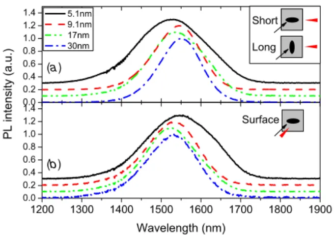
Figure 1 shows the spectrum of the multilayer samples as obtained without polarization analysis for (a) edge emission and (b) surface emission. Note that carriers are injected non-resonantly in the QDs, as the excitation energy is higher than the barrier material bandgap. Due to numerous relaxation events taking place between the carrier excitation and the emission, the polarization information related to the excitation source is lost. Therefore, the results presented are independent of the N d : Y V O4 vertical polarization state. The edge
emission spectra obtained for the LA and SA geometry are the same once normalized (only SA shown here). All samples show peak emission around 1550 nm with some variations within growth reproducibility. The main difference between the samples lies in the significantly wider linewidth of the 5.1 nm period sample. This can be explained either by the QDs progressive enlargement from one layer to the next due to strain propagation [19,20], or by coupling between the QD layers. This ambiguity supports the need for polarization measurements, sensitive to coupling and QD shape.
(a)
(b)
Figure 1.Short-axis (SA) edge emission (a) and surface emission (b) spectra for different stacking periods. LA emission is the same as SA. Inset: excitation and detection configuration, arrows representing impinging laser and red cones the emitted light.
Figure2shows the emission polarization dependence for the samples with varying stack period. In panel (a), the results for the SA geometry are shown, where 0◦ (90◦) designate light
polarization along the short axis (growth axis) of the QDs. One can see that as the layers are brought closer, the degree of polarization (DOP), defined as
DOP = Imax− Imin Imax+ Imin
, (1)
decreases from 80% to 40%. Neglecting changes in LH– HH mixing, the DOP is representative of the wavefunction symmetry, where elongation of the wavefunction in one direction will cause the photons to be polarized in the same direction. 8k·p calculations on InAs/GaAs QDs have already proven that the LH–HH wavefunction proportion changes mostly for dot periods below 5 nm, so for the 30 nm to 5 nm period range the HH–LH splitting remains high [21]. For the samples under study, even in the SA geometry the aspect ratio (QD width/thickness) is very high (∼25 nm/∼4 nm), hence the almost perfect TE polarization of the uncoupled layers (single layer and 30 nm period). A significant decrease in the DOP is obtained mainly for the 5.1 nm period sample, suggesting that electronic coupling causes the wavefunction to become more symmetric. One might think that the same argument should apply for the LA measurement geometry; however, no change in DOP was observed in that case (figure2(c)). The answer to this puzzle is revealed by the polarization dependence of the surface emission, shown in figure2(b). Results show that QDs are anisotropic, elongated along [¯1 1 0] with an aspect ratio of ∼1.5 [22] and that layer period reduction results in an increase of surface DOP, from 15% to 40%. This suggests an effective QD wavefunction elongation in the plane as dot period distance reduces, from aspect ratio ∼1.5 to ∼2. Therefore, in the LA geometry, the decrease in the wavefunction aspect ratio due to vertical coupling as the stacking period is reduced is offset by an effective elongation of the QDs, thus resulting in an unchanged DOP.
The above results highlight the importance of obtaining cylindrically symmetric QDs, as the shape anisotropy is
Semicond. Sci. Technol. 25 (2010) 045001 D Roy-Guay et al
(a)
(b)
(c)
Figure 2.Polarization PL polar plots of the GS emission in (a) SA measurement geometry and (b) surface measurement geometry. (c) Summary of the change in the degree of polarization in function of the dot period for PL in the LA, SA and surface geometry. Open symbols represent single-layer measurements, shown for comparison.
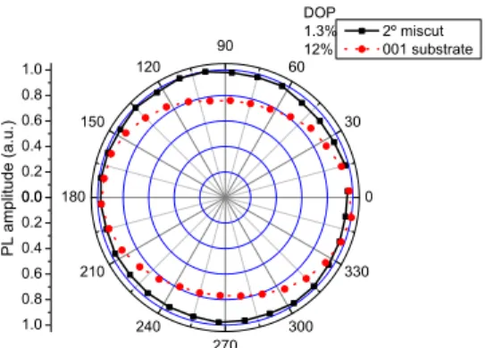
Figure 3.Change in top DOP from 12% to 1% with the use of a 2◦
miscut substrate.
detrimental to both planar and surface propagating devices. For surface propagating devices, it is obvious that symmetrical QDs would cure the polarization dependence. For planar
devices, the difficulties are highlighted if one considers the example of a ridge QD laser. Best coupling to the ridge modes is achieved by aligning the ridge perpendicular to the elongation of the QDs (LA geometry), in our case in the [1 1 0] direction. However, to achieve polarization insensitivity in ridge QD lasers or SOAs, one would have to use the SA geometry. This was shown to lead to a loss in the TE mode oscillator strength and therefore a loss in device performance [23]. To solve the QD asymmetry, we remark that formation of terraces on miscut substrates of GaAs has already proven higher dot density growth and smaller dot size distribution due to the suppression of adatom diffusion between dots separated by the terraces [24, 25]. We apply this strategy to our QDs grown on InP, where a replica of the four QD layer samples with a stacking period of 17 nm was grown on a 2◦ miscut
substrate. Comparison of the polarization dependence of the surface emission for both samples is shown in figure3. An almost isotropic polarization emission is achieved, where the DOP was reduced from 10% in the (0 0 1) substrate to almost 0% in the miscut substrate, indicating that terraces eliminate the natural elongation of QDs along [¯1 1 0]. This neutralization of the elongation can potentially eliminate the elongation of the wavefunction with decreasing stacking period, which was detrimental to the control of the polarization properties in the planar geometry.
4. Summary
In conclusion, we showed that reducing the dot period of a QD layer stack elongates the wavefunction of InAs dots in InGaAsP and induces coupling between the layers. Edge emission in the short-axis (SA) geometry shows a reduction of DOP from ∼80% in uncoupled layers down to ∼40% in strongly coupled layers. Conversely, no change in DOP was observed in the LA geometry. Although complete isotropic polarization for planar propagation devices was not achieved, further reducing the stacking period or increasing the number of layers should lead to further improvements. For surface propagation, it was shown that growth of QDs on a miscut substrate eliminates the QD elongation, thereby leading to polarization-independent surface emission. Thus, by careful control of the individual QD geometry, stacking period and number of layers, one could achieve polarization insensitivity for both planar and surface propagating QD devices emitting in the telecommunication wavelength range.
References
[1] Mathur A and Dapkus P D 1992 Appl. Phys. Lett.612845–7
[2] Seiferth F et al 1997 IEEE Photon. Technol. Lett.91340–2
[3] Zhou D et al 2009 Appl. Phys. Lett.94081107
[4] Poole P et al 2009 J. Cryst. Growth3111482–6
[5] Allen C N et al 2006 Appl. Phys. Lett.88113109
[6] Lu Z G et al 2009 Opt. Express1713609–14
[7] Lu Z G et al 2008 Opt. Express1610835–40
[8] Shi L W et al 2007 J. Phys. D: Appl. Phys.40R307–18
[9] Joma M et al 1993 Appl. Phys. Lett.62121–2
[10] Saito H et al 1996 Appl. Phys. Lett.693140–2
[11] Lamy J M et al 2009 Appl. Phys. Lett.95011117
Semicond. Sci. Technol. 25 (2010) 045001 D Roy-Guay et al
[12] Jayavel P et al 2004 Appl. Phys. Lett.841820–2
[13] Yu P et al 1999 Phys. Rev. B6016680–5
[14] Anantathanasarn S et al 2008 Appl. Phys. Lett.92123113
[15] Kawaguchi K et al 2008 Appl. Phys. Lett.93121908
[16] Allen C N et al 2001 Appl. Phys. Lett.792701–3
[17] Tatebayashi J et al 2009 J. Phys. D: Appl. Phys.42073002
[18] Poole P J et al 2001 J. Vac. Sci. Technol. B191467–70
[19] Wasilewski Z R et al 1999 J. Cryst. Growth201–2021131–5
[20] Ouattara L et al 2004 Nanotechnology151701–7
[21] Saito T et al 2005 Physica E26217–21
[22] Sheng W 2006 Appl. Phys. Lett.89173129
[23] Manz Y M et al 2003 Appl. Phys. Lett.83887–9
[24] Evtikhiev V et al 1998 Semiconductors32765–9
[25] Evtikhiev V et al 2002 Semicond. Sci. Technol.17545–50