Publisher’s version / Version de l'éditeur:
Vous avez des questions? Nous pouvons vous aider. Pour communiquer directement avec un auteur, consultez la première page de la revue dans laquelle son article a été publié afin de trouver ses coordonnées. Si vous n’arrivez pas à les repérer, communiquez avec nous à PublicationsArchive-ArchivesPublications@nrc-cnrc.gc.ca.
Questions? Contact the NRC Publications Archive team at
PublicationsArchive-ArchivesPublications@nrc-cnrc.gc.ca. If you wish to email the authors directly, please see the first page of the publication for their contact information.
https://publications-cnrc.canada.ca/fra/droits
L’accès à ce site Web et l’utilisation de son contenu sont assujettis aux conditions présentées dans le site LISEZ CES CONDITIONS ATTENTIVEMENT AVANT D’UTILISER CE SITE WEB.
8th Canadian Marine Hydromechanics and Structures Conference [Proceedings],
2007
READ THESE TERMS AND CONDITIONS CAREFULLY BEFORE USING THIS WEBSITE. https://nrc-publications.canada.ca/eng/copyright
NRC Publications Archive Record / Notice des Archives des publications du CNRC :
https://nrc-publications.canada.ca/eng/view/object/?id=cc00560f-311f-4f1e-88b1-3e3b82cb025e https://publications-cnrc.canada.ca/fra/voir/objet/?id=cc00560f-311f-4f1e-88b1-3e3b82cb025e
Archives des publications du CNRC
This publication could be one of several versions: author’s original, accepted manuscript or the publisher’s version. / La version de cette publication peut être l’une des suivantes : la version prépublication de l’auteur, la version acceptée du manuscrit ou la version de l’éditeur.
Access and use of this website and the material on it are subject to the Terms and Conditions set forth at
Overview of hydrodynamic research effort to derive a new stern design
for the Halifax Class frigates
Overview of Hydrodynamic Research Effort to Derive a
New Stern Design for the HALIFAX Class Frigates
Cumming D.
1, Pallard, R.
1, Thornhill E.
2, Hally, D.
2and Dervin M.
31
Institute for Ocean Technology, National Research Council Canada St. John’s, NL, A1B 3T5, Canada
2
Defence R&D Canada – Atlantic, Department of National Defence, Dartmouth, NS, B2Y 3Z7, Canada
3
Directorate of Maritime Ship Support, Department of National Defence, Dartmouth, NS, B2Y 3Z7, Canada
Email: David.Cumming@nrc-cnrc.gc.ca
A
BSTRACTThe HALIFAX Class frigates comprise a class of 12 warships that will represent Canada’s primary naval defence capability well into the 21st century. Driven by a concern regarding the escalating cost of fuel to operate the HALIFAX Class frigates, the Institute for Ocean Technology (IOT) was contracted by the Department of National Defence (DND) to carry out research, in collaboration with the Defence R&D Canada – Atlantic (DRDC-Atlantic), to develop a viable stern appendage that will reduce the hydrodynamic resistance for a Class-wide blended annual speed profile with secondary benefits such as an increase in forward speed, improved propeller cavitation performance and a reduced stern wave system. This paper provides a detailed description of the hydrodynamic design process adopted to design a suitable appendage.
1. INTRODUCTION
The HALIFAX Class frigates will commence an extensive Frigate Equipment Life Extension (FELEX) program beginning in 2010 that is expected to extend the life expectancy for this Class by at least 15 to 20 years. Research carried out by the U.S. Navy has shown that the addition of a suitable stern appendage can reduce fuel costs from 5 to 10% depending on the operational profile of the ship [1], [2]. The project team was tasked to design a suitable stern appendage for two hull configurations - the existing ship as well as the existing ship with the
stern extended by 2 m. This paper provides a detailed description of the hydrodynamic design process to develop an optimum stern appendage that includes a literature review, extensive physical and numerical modeling, data analysis procedure and some example results.
2. HALIFAX CLASS FRIGATES
The HALIFAX Class frigates are multi-purpose twin screw vessels fitted with inboard turning controllable pitch propellers rotating at the outboard termination of a set of long exposed shafts supported by two sets of ‘A’ brackets. Other appendages include a large centerline rudder, a set of bilge keels and a centerline sonar dome fitted near the bow – see Figure 1 (profile view).
Figure 1: HALIFAX Class Frigate Profile View
3. PRELIMINARY INVESTIGATION
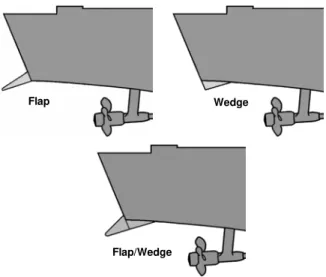
Literature Search: The first step was to perform an extensive literature review to examine the results of previous R & D related to deriving successful monohullstern flap, stern wedge andintegrated stern
wedge-flap appendage design options (Figure 2). An overview of the effort carried out both within Canada as well as by foreign (primarily American) agencies was included. In addition to the extensive body of work described in the open literature, IOT benefited from being granted liberal access to restricted U.S Navy model test reports. Due to the proximity of the trailing edge of the large centerline rudder to the transom, only flaps were considered for the existing hull however all options were viable for the existing hull extended by 2 m.
Flap Wedge
Flap/Wedge
Figure 2: Flap/Wedge Configurations
The project plan was refined based on the information in the available documents.
Numerical Simulations: To further reduce the scope of the physical model tests, DRDC-Atlantic was tasked to perform numerical simulations to assess the influence of a range of stern appendages using the commercial Computational Fluid Dynamics (CFD) software CFX 5.7.11 as well as the potential flow code DCHERIE. CFX uses the finite volume method to discretize the Reynolds-averaged Navier-Stokes (RANS) equations governing fluid motion with options for several turbulence models. Simulations involving a free surface (air/water interface) employ the volume-of-fluid (VOF) interface capturing method. Simulations were run in the steady-state mode with a physical time scale of 0.1 seconds. In general, the default k-ε turbulence model was used
and 150 iterations were performed for each
simulation. Example results of the simulation for a range of flap chord lengths and angles on the existing hull are illustrated in Figure 3.
1
© ANSYS Inc. All rights reserved.
-1.0% 0.0% 1.0% 2.0% 3.0% 4.0% 5.0% 6.0% 0 5 10 15 20 25
Stern Flap Angle [deg]
D e c rea se i n R e si st an c e 1.0% LBP 1.5% LBP 2.0% LBP 2.5% LBP
Figure 3: Example CFD Results
DCHERIE was used to calculate the potential flow around the hull with free surface for all stern appendage options on both the existing ship and existing ship extended by 2 m. DCHERIE is a modified version of the program CHERIE developed by the Bassin d’Essais des Carènes (BEC) in France [3]. It is an implementation of Dawson’s method [4] in which Rankine sources are distributed over both the hull and free surface. In this strategy, the free surface is not satisfied explicitly; it must be satisfied by adjusting the values of the source of the panels on the free surface.
The results from the numerical simulations suggested an optimum flap angle of between 3º and 13º with an optimum flap chord length of between 1.0% and 1.5% of the existing ship length (LBP). The flap should be as wide as possible without causing problems in design, construction and fitting.
4. BARE HULL MODEL TESTS
Model Description: Bare hull model tests were carried out on a 1:13.55 scale representation of the
HALIFAX Class frigate fabricated from glass
reinforced plastic and included significant internal plywood stiffening. All experiments were performed at a full scale draft of 5.34 m level trim – the midpoint between post-FELEX Operational Light and end of life condition. The nominal principal particulars for the existing ship and model are provided in Table 1.
Particular Ship Model
Length (LBP) 124.5 m 9.19 m
Max WL Beam 15.1 m 1.11 m
Draft 5.34 m 0.394 m
Displacement 5238 t 2057 kg
The model design included two stern segment options – one for the existing hull length and one for the existing hull extended by 2 m full scale. The hull was extended by extrapolating the gently upward sloping buttock lines at the stern. It was an important design consideration to be able to change from existing to extended hull length as well as change the various stern appendage options quickly without having to remove the model from under the tow carriage. Eight stern flaps were fabricated - two chord lengths (1% and 1.5% of LBP) and four angles (4, 7, 10, 13 degrees) trailing edge down relative to the horizontal that could be fitted to either the existing or extended hull. In addition, two wedges (1% LBP - 4 and 7 degrees) were available to be used on the extended hull only.
Instrumentation: In addition to acquiring the usual resistance parameters (model speed, tow force, sinkage, trim), additional sensors were added to gain a better insight into the mechanism of how stern appendages worked and also to provide data specifically to validate numerical prediction software. Thus the data acquisition plan included eight flush mounted pressure transducers distributed on the 2 m buttock line, port and starboard, from just forward of the hull segment break to Station 2. To quantify the magnitude of the wave amplitude generated by the model as it traveled down the tank (wave cut), an array of four capacitance type wave probes were fixed at the nominal mid-length of the tank on a cantilever beam extending laterally from the tank wall. Digital video images were taken of the bow and stern wave profile as well as down at the wake. High speed LineScan underwater camera images were acquired to further define the dynamic waterline and wetted surface area using dedicated MATLAB2 software.
Figure 4: Bare Hull Resistance Test
2
© 1994-2007 The MathWorks, Inc.
Test Plan: Ballast was initially moved forward to elevate the transom clear of the water to perform dedicated experiments from Fr = 0.12 to 0.20 to derive the Prohaska Form Factor. Full resistance curves from 3.5 to 31.5 knots full scale were then acquired for the level trim baseline existing and extended hull (no stern appendages fitted). To efficiently determine the optimum stern appendages, six point resistance curves were acquired from 5 to 30 knots full scale in 5 knot increments. Data for eight stern flaps were acquired for the existing hull with full resistance curves evaluated for the three most promising flaps. The test matrix for the extended hull was more complex – six point resistance curves were derived for the three optimum flaps as derived from the existing hull tests, two wedges only, and all integrated wedge/flap combinations – a total of 19 stern appendage variations in all. Full resistance curves were then evaluated for the three most promising appendages. At the request of DRDC-Atlantic, additional experiments were carried out on the extended hull only to examine the relationship between trim angle and resistance as the numerical simulations had predicted a far more sensitive relationship than anticipated. Abbreviated (11 points from 8 to 30 knots full scale) resistance data were acquired for the model with ballast adjusted longitudinally to trim the model nominally 0.5 deg. by the bow, 0.5 deg. by the stern and 1.0 deg. by the stern.
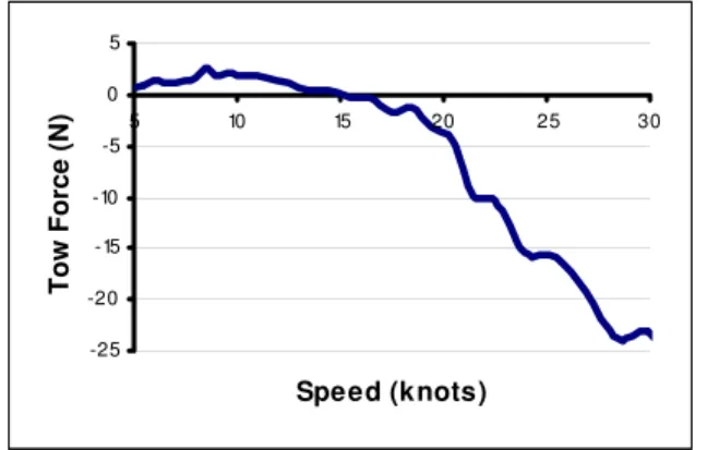
Data Analysis: Generally, the resistance of the model fitted with a stern appendage initially increased relative to the resistance of the baseline hull, at some speed there was a crossover followed by a significant benefit – see Figure 5 results for 1.5% LBP chord length, 4 deg. trailing edge down flap.
-25 -20 -15 -10 -5 0 5 5 10 15 20 25 30 Speed (knots) Tow Force (N)
Figure 5: Relative Tow Force With/Without 1.5% LBP, 4 deg. Flap
To determine the optimum stern appendage, the effective power was first computed using the standard ITTC’78 procedure [5]. The effective power
for the six point curves for each appendage configuration as well as the baseline condition was input to a Ship Endurance/Range Prediction spreadsheet furnished by DND [6] that had been tailored specifically for the HALIFAX Class frigates stern appendage project. This spreadsheet was used to compute annual fuel consumption for the various configurations assuming a blended fleet wide % time at speed profile (Figure 6). The criterion for evaluating a given stern appendage was based on the least fuel consumed for the peace-time % time at speed profile. Fuel consumption was also computed for the war-time % time at speed profile.
Figure 6: HALIFAX % Time at Speed Profile
The optimum stern appendage for both the existing hull and existing hull extended by 2 m full scale was determined to be a flap with a 1.5% LBP chord length and 4 degree angle trailing edge down relative to the horizontal spanning 7.561 m near the turn of the bilge. The estimated reduction in annual fuel consumption relative to the baseline for each hull length (no appendage fitted) is 1.08% for the existing hull and 0.67% for the extended hull based on the peace-time % time at speed profile. Figure 5 infers a speed dependence to the benefit provided by installing a stern flap and this is reflected in the higher estimated reduction in annual fuel consumption for the war-time % time at speed profile – 2.40% for the existing hull and 1.94% for the extended hull.
IOT recorded an increase in pressure under the afterbody of the model as noted by Cusanelli [2]. It was also determined that the resistance was very sensitive to trim angle. Over the speed range investigated during the trim study (8 to 30 knots full scale), there was an average resistance increase of 16.08% for 1 deg. stern down, 7.41% increase for 0.5 deg. stern down and a 5.72% decrease for 0.5 deg. bow down. It was noted that adding a stern flap to
either the existing or extended hull resulted in a minor reduction in both dynamic sinkage and trim.
5. APPENDED HULL MODEL TESTS
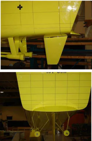
Model Description: All appendages were fitted for the appended hull experiments including two sets of ‘A’ brackets/shaft, 5-bladed inward turning stock warship propellers, a large centerline rudder, a set of bilge keels as well as a centerline sonar dome fitted near the bow. A final version of the faired stern flap was designed and fabricated with a nominal 1.5% LBP (1.8675 m full scale) chord length and 4 degree trailing edge down angle relative to the horizontal capable of being fitted to either the existing hull or the existing hull extended by 2 m full scale (see Figure 7). All propulsion experiments were carried out at the same displacement/trim condition as the bare hull resistance experiments - a full scale draft of 5.34 m level trim.
Figure 7: Final Faired Stern Flap
Custom made shaft torque/thrust dynamometers and large DC motors were procured to enable quality propulsion data to be acquired up to a maximum speed of 29+ knots full scale. Precautions were taken
to prevent RF emitted from the large propulsion motors contaminating the output from various sensors. To further explore the relationship between trim angle and resistance, provision was included in the model design to move a 200 kg ballast weight (nominally 10% of the displacement) longitudinally on a set of rails using a manually operated screw jack
rrangement to induce small trim deviations.
as sing a camera directed down at the model wake.
n at AP and 22.85 cm ll scale stern down at AP.
ixed at the level trim location for all xperiments.
28, and 29 knots full scale for the existing and a
Instrumentation: In addition to acquiring the usual resistance/propulsion parameters (model speed, tow force, sinkage, trim
,
2*thrust/torque/shaft speed), an IOT designed and built dynamometer that incorporated three vertically oriented uni-axial load cells and one longitudinally mounted uni-axial load cell was used to determine loads on the stern segments with and without the stern flap fitted. It was assumed that the difference between loads measured with and without the flap were the loads induced by the presence of the flap. Using dedicated software to analyze the dynamometer data, the following forces and moments were output from the stern balance: vertical force Fz, longitudinal force Fx, moment about the longitudinal axis Mx and moment about the lateral axis My. Digital video images were taken of the bow and stern wave profile as well uTest Plan: Full appended resistance curves from 3.5 to 31.5 knots full scale were acquired for the existing and extended hull – with and without the final faired stern flap fitted. To further investigate the relationship between trim angle and resistance, abbreviated resistance curves (10 to 30 knots full scale) were acquired on the existing hull only for the following different trims: baseline level trim, 9.33 cm full scale stern up at AP, 18.66 cm stern up at AP, 11.43 cm full scale stern dow
fu
To investigate the hydrodynamic mechanism of how stern flaps work, dedicated experiments were carried out to determine the influence of trim angle on flap effectiveness. Thus with the existing hull form only, the trim was iteratively altered by moving the 200 kg ballast weight longitudinally for all forward speeds of the abbreviated resistance curve such that the model without flap fitted assumed the same dynamic trim angle as if the flap was fitted. No effort was made to alter the dynamic sinkage and the location of the gimbal was f
e
The propellers were then fitted and self-propulsion data were acquired for speeds of 6, 10, 14, 18, 22, 26,
extended hull – with and without the final faired stern flap fitted.
Experiments were carried out from 1 to 15 knots full scale astern for the existing and extended hull – with and without the final faired stern flap fitted to assess the structural loads induced by the stern flap during a steady state astern transit.
Crash stop experiments were executed to estimate the loads imposed by the wake induced waves impacting the stern when decelerating from 10, 20 and 30 knots full scale to full astern using nominal deceleration speed profiles derived from full scale trials data. Crash stop experiments were carried out for the existing and extended hull – with and without the final faired stern flap fitted. Since during a crash stop, a transient phenomenon was being investigated and the magnitude of peak loads were important to determine, each run was repeated five times to expose any data variability and obtain a valid estimate of peak loading.
The propellers were fitted during both the astern transit and crash stop experiments however the propulsion system was not engaged.
Data Analysis: The effective power of the appended hull was computed using the standard ITTC’78 procedures [5]. Not surprisingly, there was a significant increase in resistance over the bare hull – almost 35% increase at a speed of 15 knots. Adding a flap to the existing hull resulted in a resistance decrease of 4% to 6% for forward speeds greater than 20 knots full scale. The hull friction resistance penalty incurred due to the increase in wetted surface area from lengthening the ship by 2 m is more than offset by a combination of a decreased wavemaking component due to the increase in waterline length combined with a reduction in transom separation drag since there is less of the transom exposed to the flow on the extended hull for the same level trim condition. Fitting a stern flap to the extended hull provided significant benefits above ~ 13 knots full scale over the existing hull with no flap fitted - an improvement in effective power of 7% to 9% was noted at speeds over 20 knots full scale.
The visually observed stern flap effects on the transom flow are listed as follows:
• The transverse width of the stern wave system was reduced.
• For the hull without flap, the stern waves widen rapidly as they move aft of the transom, whereas, the stern flap causes a ‘neck down’, or reduction in width, prior to the waves becoming wider moving aft.
• The total area of turbulence and whitewater is reduced.
• The transom flow breakaway speed (21 to 24 knots) is slightly reduced by the presence of a stern flap. Cleanly detached flow is indicative of reduced transom drag compared to attached flow.
•
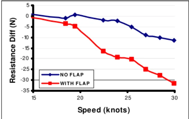
There is a reduction in wave breaking both directly behind the transom and at the edge of the inner stern wave region implying a reduction in energy in the wake.The relationship between resistance and trim angle initially explored during the bare hull experiments was further investigated using the appended model. Experiments were carried out by moving the 200 kg ballast weight longitudinally resulting in a change in trim of nominally ±20 cm at the transom full scale in 10 cm increments. An increase in resistance of 3 to 4% was noted at the nominal average peace-time speed of 15 knots full scale when the draft at the stern was increased – an increase in resistance that trended to zero as the forward speed approached 30 knots full scale. A small increase in resistance at 15 knots was noted for a slight decrease (9.33 cm full scale) in draft at the AP although a positive benefit was noted for this condition above speeds of ~ 18 knots. For a decrease in draft at the AP of 18.7 cm full scale, there was a positive benefit noted throughout the speed range from 10 to 30 knots with a reduction in resistance of ~ 1% noted at 15 knots and a maximum reduction of ~ 3% noted at a forward speed of ~ 24 knots. -35 -30 -25 -20 -15 -10 -5 0 5 15 20 25 30 Speed (knots) R esi stance D iff (N ) N O F L A P WI T H F L A P
Figure 8: Resistance Diff – Flap Induced Trim
A dedicated experiment was carried out to estimate what proportion of the effectiveness of a stern flap is due to the fact that the flap reduces the dynamic trim marginally. The 200 kg ballast weight was moved longitudinally to induce the same nominal dynamic trim change for a given forward speed on the existing hull with no stern flap fitted as if a flap was fitted. The challenge in conducting this experiment is related to iteratively attempting to effect the exact
desired trim angle (maximum trim angle at 30 knots full scale was less than 0.18 deg.). No effort was made to adjust the dynamic sinkage. It was evident from the results that a significant minority of the resistance reduction (~1/3 at the highest speeds) was due to the fact that the flap was marginally reducing the trim by the stern and the magnitude of the resistance is very sensitive to transom immersion. See Figure 8 – upper (blue) line – trim changed/no flap fitted, lower (red) line – flap induced trim change.
Standard propulsion parameters - thrust coefficient (KT), torque coefficient (10KQ) and Skin Friction Correction Coefficient (KFD) - were plotted against Average Advance Coefficient (J) for the given nominal carriage speed. Standard ITTC’78 procedures were used to predict full scale delivered power (PD). The crossover speed for delivered power on the existing ship fitted with flap relative to the ship with no flap was estimated to be 14 knots full scale with a benefit provided by the flap at speeds greater than 22 knots of nominally 7%.
There was an effort to determine whether the forward speed lost due to increasing the ship’s draft (estimated to be some 0.75 knots based on previous ship trials data) to the post-FELEX model test displacement could be recovered by adding a stern flap. Since there is no trials data available for the ship in the post-FELEX displacement condition of 5.34 m level trim condition, an estimated increase in top speed is provided using a crude assumption of maximum available power (and assuming no change in the propeller pitch settings):
• Increase in top speed of existing ship with stern flap fitted over existing ship – no flap fitted was approximately 0.44 knots full scale.
• Increase in top speed of existing ship extended by 2 m full scale (no stern flap fitted) over existing ship – no flap fitted was approximately 0.38 knots full scale.
• Increase in top speed of existing ship extended by 2 m full scale with a stern flap fitted over existing ship – no flap fitted was approximately 0.65 knots. Thus to recover the top speed of the HALIFAX Class frigate lost by increasing the displacement from an existing typical operating displacement to mid way between post-FELEX and end of life, the ship should be extended by 2 m and a stern flap fitted. Even with this expensive modification, the new top speed is estimated to be slightly lower (nominally 0.1 knots) than the top speed of the vessel in its current configuration.
The predicted delivered power was input into the Ship Endurance/Range Prediction spreadsheet furnished by DND [6] for the % time at speed profile for the HALIFAX Class frigate (Figure 6). The estimated reduction in annual fuel consumption was greater than estimated from the bare hull resistance experiments. The reduction in fuel consumption as predicted by the delivered power is 2.33% for the existing hull and 1.47% for the extended hull based on the peace-time % time at speed profile. The estimated reduction in annual fuel consumption for the war-time % time at speed profile – 3.58% for the existing hull and 2.52% for the extended hull. Note that although a fuel consumption reduction of 2.33% was predicted by fitting a flap to the existing ship – a reduction of 2.98% was observed by simply extending the stern by 2 m with no flap fitted while a remarkable 4.41% reduction was estimated over the existing ship/no flap fitted by extending the stern by 2 m and fitting a flap. All predictions assumed 100 days at sea/year.
Reviewing the forces/moments measured on the stern segment induced when the model was being towed astern:
• There is a steadily increasing longitudinal force (Fx) with increasing astern speed augmented by a relatively small increase in mean longitudinal force when the stern flap is added presumably due to the small increase in lateral area exposed to the flow. • There is a relatively small vertical force down (Fz)
on the stern segment with no flap fitted; however fitting a flap with a nominally 4 deg. angle down relative to the horizontal results in a significant increase in downward force as the speed astern increases.
• There is a negligible impact on lateral moment (Mx) for all conditions implying a generally symmetric force distribution across the stern. The addition of a stern flap has little impact on this lateral force distribution.
• Transit astern has the impact of creating a large longitudinal moment (My) bow down presumably due to the flow acting with a center of pressure that varies from approximately 2 to 3 m full scale above the moment origin (base of the transom) on the slope of the transom. The addition of a stern flap reduces this longitudinal moment somewhat as the large vertical force down on the flap induces a counter-moment.
• At the highest astern speed tested (15 knots), there was dynamic run-up for the model with flap fitted to nominally the 8 m waterline across the stern with slightly less run-up for the model without flap fitted.
For each crash stop run, the peak transient forces and moments (Fx, Fz, Mx and My) were evaluated during the constant speed, deceleration and following wave time segments. In all cases, the maximum peaks values were measured during the 30 knot crash stop, with stern flap fitted. There was considerable variation in the magnitude of the peak loading and whether the highest loads occurred as a maximum or minimum peak value, what portion of the crash stop evolution etc.. There was also greater laterally asymmetric loading during a crash stop than was noted during the astern transit experiments.
The stern loading data measured with/without a flap fitted provide a global sense of what maximum loads could be expected on the stern due to the presence of a flap. The flap itself was not instrumented as this would have significantly increased the costs/resources to carry out the experiment; however it is assumed that the difference in loading with/without flap fitted provides a reasonable estimate of global flap loads. Other than the Mx moment, the highest overall loads were incurred during high speed astern transit operations.
6. DISCUSSION
A suitable stern flap has been designed and evaluated for the existing HALIFAX Class frigate as well as the existing ship extended by 2 m full scale. The fuel consumption reductions predicted by fitting the flap would result in significant operating cost savings for the 12 ships over the remainder of their life. Based on the results of U.S. experience [1,2], additional benefits are expected to include: a reduction in loading on the propellers, a reduction in vibration and noise, an increase in propeller cavitation inception speed, a reduction in stern wave energy, a slight increase in forward speed for a given power setting and a cleaner environment due to a reduction in emissions from the ship’s power plant. IOT has recently completed a wake survey that, when the data is input to dedicated cavitation speed prediction software by DRDC-Atlantic staff, is expected to indicate that the cavitation inception speed has not been negatively affected by adding a flap.
Cusanelli’s explanation [2] of how stern flaps work is generally accepted:
“Stern flaps modify the pressure field under the hull afterbody, causing the flow to slow down over an area extending from its position to generally forward of the propellers. Decreased flow velocity causes an increase in pressure, which in turn, reduces resistance due to reduced after-body suction force (form drag).
Wave heights in the near stern wave system, and far field wave energy, are both reduced by the flap, inspiring the credo “less show – more go!” Localized flow around the transom, which represents lost energy through eddy-making, wave breaking, and turbulence, is significantly modified. The flow exit velocity from the flap trailing edge is increased relative to the transom knuckle, leading to a lower speed for clean flow separation, and further reduced resistance.
Vertical forces developed by the flap can affect the trim angle on planing and semi-planing craft, however, trim effects are negligible on displacement hulls.”
The research carried out by IOT and DRDC-Atlantic generally supports these statements. However, although it has been recognized by other researchers that the addition of a stern flap induces a marginal reduction in both dynamic sinkage and trim, it is not clear from the literature whether the significance of the change in sinkage and trim has been fully appreciated. There was a far more sensitive relationship between the draft at the transom and resistance than expected – a relationship that has since been confirmed by dedicated numerical predictions generated by DRDC-Atlantic. All things considered, a modest fuel consumption benefit would have been expected by extending the ship by 2 m. Most of the over 4% improvement is attributed to the fact that the buttock lines for the 2 m transom extension slope gradually upwards such that the transom immersion at the 2 m buttock line is 8.9 cm less full scale for the extended hull at the 5.34 m level trim displacement than for the existing stern resulting in less transom separation drag.
Other test results present no cause for concern. The forces and moments induced by the presence of the flap will have to be reviewed by structural engineers but it is expected that scantlings similar to those used to fit bilge keels can be used to add a flap.
7.
RECOMMENDATIONS
The following recommendations are made based on the results of this effort:
1) To obtain a maximum benefit over the remaining life of the HALIFAX Class frigates, a 2 m stern extension and a 1.5% LBP chord length/4 deg. down stern flap should be added. Although this is an expensive option, the costs can be mitigated if the modification is encompassed by the extensive FELEX refit and the long term benefits are deemed well worth the effort.
2) The feasibility of modifying standard operating procedures to reduce the average trim by the stern should be investigated. Relatively minor changes such as drawing fuel from an aft tank before a forward tank, for example, to reduce the
average draft at the transom by even a few cm can have a positive impact on fuel consumption. 3) Ideally, it would be valuable to evaluate the
benefit provided by a flap by carrying out a sea trial before and after flap installation. It is not recommended in this case, however, since the flap would likely be fitted during the extensive FELEX refit expected to last several months and the trial conditions will be very different post-FELEX – different displacement, clean hull/ propeller and likely different environmental conditions. It would be very difficult to isolate the benefit provided by the stern flap.
A
CKNOWLEDGEMENTSThe authors would like to acknowledge DND for funding this project and the U.S Navy for providing liberal access to stern appendage design related test/trials reports. Enthusiastic support from IOT technical staff for this project was much appreciated.
R
EFERENCES[1]
Cusanelli, D.S.,”Stern Flaps – A Chronicle of Success at Sea (1989-2002)”, Innovations in Marine Transportation, SNAME Northern California Section Joint Section Meeting, Pacific Grove, Calif. May 30-June 2, 2002.[2] Cusanelli, D.S.,”Stern Flap: An Economical Fuel-Saving, Go-Faster, Go-Farther Device for the Commercial Vessel Market”, 7th International Conference on Fast Sea Transportation
(FAST’03), Ischia, Italy.
[3] Stievenard, P.,”CHERIE: Code Hydrodynamic d’Evaluation de la Rèsistance Induite par un Ecoulement”, (Etude No. 2474 Pièce 2), Bassin d’Essais des Carènes, 1996.
[4] Dawson, C.W.,”A Practical Computer Method for Solving Ship-Wave Problems”, Proc. 2nd International Conference on Numerical Ship Hydrodynamics, University of California, Berkley, pp. 30-38, 1977.
[
5] ITTC Recommended Procedure 7.5-02-03-01.4, “1978 ITTC Performance Prediction Method”, 1999.[6]
Dervin, M.F.,”Ship Endurance / Range Prediction”, DND Reference #D-03-002-010/SG-001, (EXCEL3 Workbook), 2005.3