Publisher’s version / Version de l'éditeur:
Vous avez des questions? Nous pouvons vous aider. Pour communiquer directement avec un auteur, consultez la première page de la revue dans laquelle son article a été publié afin de trouver ses coordonnées. Si vous n’arrivez pas à les repérer, communiquez avec nous à [email protected].
Questions? Contact the NRC Publications Archive team at
[email protected]. If you wish to email the authors directly, please see the first page of the publication for their contact information.
https://publications-cnrc.canada.ca/fra/droits
L’accès à ce site Web et l’utilisation de son contenu sont assujettis aux conditions présentées dans le site LISEZ CES CONDITIONS ATTENTIVEMENT AVANT D’UTILISER CE SITE WEB.
Student Report; no. SR-2009-09, 2009-01-01
READ THESE TERMS AND CONDITIONS CAREFULLY BEFORE USING THIS WEBSITE. https://nrc-publications.canada.ca/eng/copyright
NRC Publications Archive Record / Notice des Archives des publications du CNRC :
https://nrc-publications.canada.ca/eng/view/object/?id=5eee4359-53d6-4a55-b886-5f72707fb163 https://publications-cnrc.canada.ca/fra/voir/objet/?id=5eee4359-53d6-4a55-b886-5f72707fb163
NRC Publications Archive
Archives des publications du CNRC
For the publisher’s version, please access the DOI link below./ Pour consulter la version de l’éditeur, utilisez le lien DOI ci-dessous.
https://doi.org/10.4224/18238668
Access and use of this website and the material on it are subject to the Terms and Conditions set forth at Finite Element Analysis of Motorized Adjustable Platform
National Research Council Canada Institute for Ocean Technology Conseil national de recherches Canada Institut des technologies oc ´eaniques
SR-2009-09
Student Report
Finite Element Analysis of Motorized Adjustable Platform.
Rogers, F.
Rogers, F., 2009. Finite Element Analysis of Motorized Adjustable Platform. St. John's, NL : NRC Institute for Ocean Technology. Student Report, SR-2009-09.
SUMMARY
Finite element analysis was performed on Haibing Wang’s design of a motorized adjustable platform. The analysis was done in order to produce stiffness and strength visualizations and also in minimizing weight, materials, and cost. This process was performed using ALGOR, which is a finite element analysis software package.
This report explains the steps followed in performing finite element analysis. First a wire frame was developed of Wang’s design. Then the elements were given properties. Followed by applying the loads and defining the boundary conditions. Finally the program calculated the stresses and natural frequencies needed.
The results presented were the axial stress, the bending stress around both axis and the worst stress. Also the natural frequencies of the structure were examined. From this analysis recommendations were given on what should be changed on the motorized adjustable platform.
TABLE OF CONTENTS
1.0 ORGANIZAION DESCRIPTION……….1
2.0 INTRODUCTION / BACKGROUND………...2
2.1 Statement of the Problem……….…2
2.2 Structure Description………2
3.0 INTRODUCTION TO FINITE ELEMENT ANALYSIS………3
3.1 Finite Element Analysis……….…..3
3.2 Finite Element Analysis Steps………..3
4.0 PROCEDURE………...4
4.1 Model the Structure………..4
4.2 Define each Element Properties………4
4.2.1 Square Structural Tubing………5
4.2.2. Linear Bearings..………6
4.2.3. Ball Screw………..7
4.3 Applying the Loads………7
4.4 Defined Boundary Conditions………...………9
4.5 Calculating the Stresses………..…...9
5.0 CONCLUSION……….………10
6.0 RECOMMENDATIONS……….10
APPENDIX A: Picutres APPENDIX B: Figures REFERENCES
1. Organization Description
The Institute for Ocean Technology (IOT) was established in 1985 to provide technical expertise in support of Canada's ocean technology industries. The Institute's capability is unique to the nation — no other organization offers the combination of knowledge, experience and world-class facilities. IOT conducts ocean engineering research through modeling of ocean environments, predicting and improving the performance of marine systems, and developing innovative technologies that bring benefits to the Canadian marine industry.
IOT has established a worldwide reputation for the excellence of its work, building an impressive record of collaborative and contractual research and a history of solid scientific achievement. It has helped to commercialize vessel prototypes, offshore technologies, underwater systems and more. Ongoing research projects provide the long-term investment in knowledge required for Canada to compete in the international marketplace of the 21st century.
In 2003 the Institute officially opened its Ocean Technology Enterprise Centre, a facility to assist in the growth and development of new ventures in ocean technology. With a Young Entrepreneurs Program and an Ocean Technology Co-Location Program, the centre helps new and established enterprises to develop their concepts and technologies in a supportive environment, with access to IOT facilities and expertise. 1
1
2. Introduction/ Background
2.1. Statement of the Problem
A former work term student, Haibing Wang, recognized the need for a better way of getting from the tow tank carriage deck to the water. As of now, the test technician has to climb up one side of the ladder and down the other side to reach the platform (See Picture 1. in Appendix). The technician also has to reach over the side of the platform in order to reach the water. He does this while holding the test models with both hands. The technician has to repeat this process repeatedly, which gets very frustrating and tiring over time. This increases testing time and total project cost.
Another problem with the existing platform is that it is a fixed platform. When the testing is being run the model can strike the platform and cause serious damage to the model. This will not only affect the results of the tests, but also delay project progress. When the model is damaged, all testing technicians, researchers, and supporting crews have to wait for the model to be fixed. These damages have been seen to exceed over thousands of dollars.
2.2. Structure Description
Wang completed a conceptual design for a Motorized Adjustable Platform (See Fig. 1. in Appendix). His design consisted of a 2.5-ton high lead ball screw jack and a 1.5 hp electric motor with break. The mounting frame would be bolted onto the front of the tow tank carriage. The moving frame would be connected to the mounting frame’s two parallel profile rails at four points. For more information on the structure see Haibing’s report titled, Motorized Adjustable Platform for Tow Tank Carriage.
3. Introduction to Finite Element Analysis
3.1. Finite Element Analysis
Finite Element Analysis is a computer based procedure that can be used to analyze structures and continua. It is a versatile numerical method that is widely applied to solve problems covering almost the whole spectrum of engineering analysis. Common applications include static, dynamic, and thermal behavior of physical systems, and their components. Advances in computer hardware have made it easier and very efficient to use finite element software for the solution of complex engineering problems on personal computers.
The results obtained with a finite element analysis are rarely “exact”. Nevertheless, a very accurate solution can be obtained if a proper finite element model, based on principles of finite element analysis, is used.2
3.2. Finite Element Analysis Steps
1. Model the Structure:This step the structure is divided into finite elements. This is the most crucial step in determining the solution accuracy of the problem. If the model is not designed exactly like the structure the results will be off.
2. Defining each Elements Properties:
Here the user must define the element properties and select types of finite elements that are the most suitable to model the physical structure.
3. Applying the Loads:
Externally applied concentrated or uniform forces, moments, and ground moments are provided at this step.
4. User Defined Boundary Conditions:
The support conditions must be provided. Which means several nodal displacements must be set to known values.
5. Calculating Needed Stresses:
At the users discretion, the programs can calculate stresses, reactions or any needed information.2
4. Procedure
4.1. Model the Structure
To begin finite element analysis, a skeletal wire frame drawing of the structure is made. The centerline axis was drawn through the centroids of each member of the frame. Next the centerline of the ball screw was used to show where it was in the skeletal drawing. Finally the linear bearings were taken into consideration. Since the linear bearings are complex mechanisms to model, they were represented by a flexible link. A flexible link is a beam designed to be tall and thin, meaning it is weak in only one axis of rotation. Drawing the rollers as a single element flex link, will show us how much normal force the linear bearings will have to be able to withhold. Fig.2. shows the final skeletal drawing.
4.2. Define each Element Properties
The next step after making the skeletal model of the structure was to load this drawing into ALGOR. ALOGR is a general-purpose multiphysics finite element analysis software package. The first thing to do then was to assign each element with its physical properties.
2
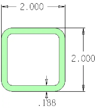
4.2.1 Square Structural Tubing
The Square Structural Tubing members were represented as beam element. Beam element was chose because it will produce an axial force and will show bending moments due to joint stiffness. The dimensions of the tubing are 2 inch height and width and 0.188 inch thickness. This is shown in Fig. 3. The material modulus was 1020 steel and had an area of 1.36 in2. The moment of inertia for square structural tubing was calculated to be 0.754 in4.
Fig. 3. Square Structural Tubing
Area = Outside Area – Inside Area A= (D2)o – (d2)I
(2in 2in) – (1.624in 1.624in)= 1.363 in3
Moment of Inertia=
Moment of Inertia of outside square – Moment of Inertia of inside square
(1/12 2in (2in) 3)- (1/12 1.624in (1.624in) 3) = 0.7537 in4
4.2.2. Linear Bearings
The elements for the linear bearings were represented as beam elements made of 1020 steel. To calculate the cross sectional dimensions to represent the linear bearings, the following steps were taken:
Find k (stiffness) of the ball screw, k ball screw = EA/ l
Modulus of Elasticity (E)= 29 X103 ksi or 29008000 lbf/ in2 Area (A)= 0.7854 in2
Length (l)= 70.205 in k ball screw = 324429.9 lbf/ in
To represent the rollers, by permitting free movement in the z direction, a stiffness of 100 times less than the ball screw was required.
k roller = (324429.9/ 100)/ 4 = 811.1 lbf/in
Note: The reason it is also divided by four is because there are four linear bearings.
Once the k of the roller was found we could find the moment of inertia, I= (kl3)/ 3E
I= ((811.1 lbf/in)(3.167in) 3 )/(329008000 lbf/in2) I= 2.961 X10⁻⁴
With this moment of inertia, the dimensions for the linear bearings can be found using the following equation,
-After substituting different b values into this equation and finding maximum area, the following was found:
b=0.5 in
I= 1/12 a b3
2.961 X10-4 = 1/12 a(0.5) 3 -solving for a
a= 0.5 in
Maximum area= (0.5 in)(0.5 in)= 0.25 in2
-These dimensions were chosen because they yielded the highest stiffness.
Fig. 4. Flexible link
4.2.3. Ball Screw
The ball screw was also defined as a beam element. It was represented as a round shaft made of 1020 steel and had an area of 0.7854 in2. The moment of inertia for the ball screw was calculated to be 0.05 in4
4.3. Applying the Loads
The load to be applied came from “National Building Code of Canada 2005”. The adjustable platform was defined as a footbridge. This meant that it had a minimum specified load of 4.8 kPa.
First convert to PSI or lbs/in2: 4.8 kPa = 0.6962 PSI or lbs/in2
The Area of the platform was 1896.54 in2 -with this the load could be found, 1896.54 in2 0.6962 lbs/in2
= 1320.37 lbs
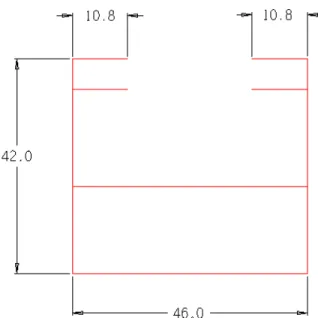
Next thing that was needed was the parameter of the platform supports where the load would be applied,
Fig. 5. Platform Support Parameter
Parameter= 219.2 in
From this the distributed load was found, Distributed Load= 1320.37 lbs/ 219.2 in = 6.02 lbs/in
-This distributed load was then applied to the platform supports in the wire frame.
4.4. Defined Boundary Conditions
The boundary conditions are what fixes the structure in space and constrains motion. For the adjustable platform, this is where the mounting structure will be bolted onto the tow tank carriage. The boundary conditions are the red circles on the wire frame in Fig. 6. in the appendix. The conditions were set that at these points with pin connections, there would be no movement in the x, y or z directions, but rotation of the joints were allowed.
4.5. Calculating the Stresses
Once ALGOR processed the structure with the load applied the results were generated. The results presented were the axial stress, the bending stress around both axis and the worst stress with was all three combined. The natural frequencies of the structure were also examined at in the results.
The axial stress showed a maximum force at the rollers of 703.95 lb. This stress is well below the ability of what the linear bearings can hold. The highest force in the square structural tubing was 1738.4 lb. The ball screw showed the lowest force in the axial stress test, with only 224.2 lb.
From looking at the worst stress it showed high forces in the rollers at 6787.75 lb. The top two linear bearings experienced a tension of this magnitude. While the bottom two experienced the same magnitude but in compression. The rollers will not feel the bending forces that were show here. This is because the bending stresses generated in the flex links are not representative of the actual bearings. The linear bearings are free to move axially and could therefore not generate any bending moments. When in actual fact the rollers only experience a normal force.
The results of the vibrational analysis shows that the first five modes of natural vibration were as follows: 0.37954 Hz, 0.402689 Hz, 0.473655 Hz, 0.494148 Hz and 0.931965 Hz. At these frequencies the structure would shake, twist and rock in different ways. This is not a good thing because it puts extra stresses on the structure. Ideally the frequencies should be above 10 Hz to prevent harmonic vibrations.
5. Conclusion
Finite Element Analysis was performed on Haibing Wang’s conceptual design of a Motorized Adjustable Platform in order to highlight any problems with his design The main conclusions from the analysis are:
1) From these results of the stress analysis, it was noticed that the mounting frame had stresses in it that were well below the acceptable limits.
11
2) Results of the natural frequency analysis shows that the natural frequencies were to low.
6. Recommendations
1) The square structural tubing should be made of thinner tubing. This would minimize the weight and the structure and also cut down on the cost.
2) Extra support should be added to stiffen the moving frame. As well some of the supports in the mounting frame could be removed.
7. Appendix
7.1. Pictures
7.2. Figures
Fig. 1. Motorized Adjustable Platform
Fig. 2. Wire frame
Fig. 4. Flexible link
Fig. 5. Platform support parameter
Fig. 6. Wire frame with defined elements, load, and boundary conditions
6
8. References
1. http://iot-ito.nrc-cnrc.gc.ca/about_e.html
2. “Motorized Adjustable Platform for Tow Tank Carriage” by Haibing Wang 3. “Finite Element Modeling in Engineering Practice” by Constantine C. Spyrakos