Automated Motion Planning for Robotic Assembly
of Discrete Architectural Structures
by
Yijiang Huang
B.S. Mathematics,
University of Science and Technology of China (2016)
Submitted to the Department of Architecture
in partial fulfillment of the requirements for the degree of
Master of Science in Building Technology
at the
MASSACHUSETTS INSTITUTE OF TECHNOLOGY
June 2018
©Yijiang Huang, 2018. All rights reserved.
The author hereby grants to MIT permission to reproduce and to
distribute publicly paper and electronic copies of this thesis document
in whole or in part in any medium now known or hereafter created.
Author . . . .
Department of Architecture
May 24, 2018
Certified by. . . .
Caitlin T. Mueller
Associate Professor of Architecture
and Civil and Environmental Engineering
Thesis Supervisor
Accepted by . . . .
Sheila Kennedy
Professor of Architecture,
Chair of the Department Committee on Graduate Students
Automated Motion Planning for Robotic Assembly of
Discrete Architectural Structures
by
Yijiang Huang
Submitted to the Department of Architecture on May 24, 2018, in partial fulfillment of the
requirements for the degree of
Master of Science in Building Technology
Abstract
Architectural robotics has proven a promising technique for assembling non-standard configurations of building components at the scale of the built environment, com-plementing the earlier revolution in generative digital design. However, despite the advantages of dexterity and precision, the time investment in solving the construc-tion sequence and associated robotic moconstruc-tion grows increasingly with the topological complexity of the target design. This gap between parametric design and robotic fabrication congests the overall digital design/production process and often confines designers to geometries with standard topology.
In the goal of filling this gap, this research presents a new robotic assembly plan-ning framework called Choreo, which eliminates human-intervention for parts that are typically arduous and tedious in architectural robotics projects. Specifically, Choreo takes discrete spatial structure as input, and then assembly sequence, end effector pose, joint configuration, and transition trajectory are all generated auto-matically. Choreo embodies novelties in both algorithm design and software imple-mentation. Algorithm-wise, a three-layer hierarchical assembly planning framework is proposed, to gradually narrow down the computational complexity along the deep and branched search tree emerging in this combined task and motion planning prob-lem. Implementation-wise, Choreo’s system architecture is designed to be modu-larized and adaptable, with the emphasis on being hardware-agnostic and forging a smooth integration into existing digital design-build workflow. Case studies on fab-rication results of robotic extrusion (also called spatial 3D printing) are presented to demonstrate Choreo’s power on efficiently generating feasible robotic instructions for assembling shapes with non-standard topology and across the scales.
Thesis Supervisor: Caitlin T. Mueller Title: Associate Professor of Architecture and Civil and Environmental Engineering
“Le vent se lève!...”
Acknowledgments
First of all, I would like to express my thanks to my advisor, Caitlin Mueller, for her generosity, encouragement, and support throughout my application, research, and my life at MIT. She showed me many important facets of academia, and taught me to always do research and teaching with a big picture in mind, and most importantly with curiosity, enthusiasm, and joy. The work presented in this thesis originated from the intellectual freedom and flexibility that she gave me. I am excited and honored to continue exploring my interest in computational geometry and robotic planning with her as a Ph.D. student in the next few years.
I would like to thank all of my friends and colleagues at MIT, past and present, for making this place such a open-minded and warm place for research and living. I especially wish to thank my Building Technology family for their love and intellectual support; Caelan Garrett at MIT CSAIL for his patience and passion on many pro-ductive discussions since the very beginning of this research; Prof. Michel Goemans at MIT Mathematics and Prof. Brian Williams at MIT CSAIL for their brilliant teaching and research discussions, from which I was exposed to many ingredients of this thesis; my students at 4.S48 Design for Robotic Assembly for their passion, tal-ent and creativity that showed me the joy of teaching, and their endurance on their first-time TA; Justin Lavellee, Jen O’Brien, and Chris Stewart for their patience and help on supporting the physical making involved in this studies; Duncan Kincaid and his colleagues at CRON for their efforts on maintaining the computing and plotting machines; MIT’s soccer community for always being there and ready to play when I get stuck in my research.
I want to express my gratitude to my fiancée Stella Zhujing Zhang, for her love, caring and faith in my abilities. She was always present even when I was deeply lost in my research with my unblinking gaze at the screen or unrestful pacing in front of the white board. Her purity, gentleness and love towards nature and humanity shines a special beam of light on my life and my work. I wish that we can continue to push the boundary of knowledge together forever. Finally, it is hard to adequately express
my gratitude and thanks to my parents for giving me the resources, support and love to pursue my dream.
Contents
1 Introduction 11
1.1 Background . . . 11
1.1.1 Overview . . . 11
1.1.2 Scope and assumptions . . . 12
1.1.3 Challenges . . . 13
1.2 Related work . . . 13
1.2.1 Robotic assembly for architecture . . . 14
1.2.2 Classic assembly planning . . . 15
1.2.3 Computer graphics . . . 18
1.2.4 Manipulation planning . . . 21
1.2.5 Task and motion planning . . . 24
1.3 Thesis outline . . . 28
2 Methodology 29 2.1 Conceptual overview . . . 29
2.2 Model input . . . 33
2.3 Sequence planning module . . . 33
2.3.1 Problem formulation . . . 34
2.3.2 Solving the CSP . . . 40
2.4 Motion planning module . . . 43
2.4.1 Semi-constrained Cartesian planning . . . 44
2.4.2 Retraction planning . . . 51
2.5 Post processing module . . . 52
2.5.1 Synthesis of hardware IO commands and trajectories . . . 53
2.5.2 Application-oriented path modification . . . 54
2.5.3 High-level base plan for online robotic control systems . . . . 55
2.6 Implementation . . . 55
2.6.1 System architecture overview . . . 56
2.6.2 Assembly problem setup . . . 56
2.6.3 Sequence planning . . . 58
2.6.4 Motion planning . . . 58
2.6.5 Simulation . . . 59
2.6.6 Post-processing and fine-tuning . . . 59
2.6.7 Robotic execution . . . 60
3 Case studies 61 3.1 3D Voronoi . . . 62
3.2 Mars habitat design . . . 64
3.3 Topology optimized simply-supported beam . . . 65
4 Conclusions 67 4.1 Summary of contributions . . . 68
4.2 Potential impact . . . 69
4.3 Limitations and future work . . . 69
Chapter 1
Introduction
1.1 Background
1.1.1 Overview
Architectural robotics has proven a promising technique for assembling nonstandard configurations of building components at the scale of the built environment, comple-menting the earlier revolution in generative digital design. In recent years, the sharp reduction of industrial robotics’ cost has made investment in these advanced manu-facturing machines more accessible than ever, converting the industrial robot into a cost efficient tool to materialize bespoke design [UNESCE, 2005].
However, despite the advantages of the decreasing hardware cost, dexterity, and precision of these multi-axis machines, the time investment in solving the construc-tion sequence and associated robotic moconstruc-tion grows increasingly with the topological complexity of the target design. The level of automation in this design-assemble workflow is still comparably low, due to the technical challenge of finding a feasi-ble assembly sequence and generating trajectories for the multi-axis robots. While transitioning between a digital design model and machine code for a 3-axis gantry machine is easy and direct, for multi-axis robots, gaining fine levels of control and bypassing the complexity of generating collision-free robotic trajectory is much more nuanced and subtle, which requires significant effort. Existing investigations in the
field of architectural robotics often involve manual planning of a path guidance for the robot’s end effector, followed with tedious diagnosis for potential problems in a trial-and-error manner. This slow and convoluted workflow deviates from the initial purpose of having such a digital design-assemble workflow: to forge a smooth and direct transition from digital design to real-world machine materialization; instead, the current process requires a complete re-program for the robot whenever the target geometry has a small change. This technical challenge in the assembly planning and programming of the robots congests the overall digital design / production process and often confines designers to geometries with standard topology with repetitive patterns. In order to close this gap and enable more possibilities for discrete architec-tural robotic assembly, an automated assembly planning system is needed, which calls for a more systematic and explicit computational exploration of assembly constraints and robotic motion planning.
This thesis presents a new algorithmic framework for robotic assembly planning, which embodies an hierarchical algorithm to integrate assembly sequence and motion planning. The planning framework is implemented as a flexible assembly planning tool, called Choreo, that allows users to input unconstrained spatial structures, and harvest automatically generated feasible assembly sequence and robotic trajectories. Case studies are presented to show the computational planning system’s power in enabling automated planning for robotic assembly of complex structures with non-standard topologies, which hasn’t been shown possible before.
1.1.2 Scope and assumptions
Discrete spatial structure’s definition broadly includes all the 3D structures that are consist of individual elements, which are connected to each other via structural joints and behave as a system when load is applied. The assembly planning problem is defined as: given a discrete spatial structure’s design model, the robot needs to be assigned a coordinated sequence of transition and assemble actions, to manipulate raw or sorted individual elements in a specific order to construct the designated design. There are essentially two main classes of robotic assembly applications: (1) spatial
extrusion (also called spatial 3D printing) and (2) spatial positioning (also called pick-and-place). In this thesis, for demonstration purpose, all the algorithmic framework description and case studies use spatial extrusion with a fix-base industrial robot arm as a concrete problem instance. However, the planning framework and the assembly planning tool can be configured to work with spatial positioning and the author is currently working on the implementation to support this.
In this thesis, the computation of the planning is all performed offline before execution. The robot is assumed to work in a deterministic world, which means that it optimistically believe that the environment that it is interacting with will behave exactly as specified in the computed plan. The planning is constrained to be purely geometric that the generated plan does not have a meaningful time parametrization embedded, and thus does not address the dynamics of the system. A fixed-base robot is assumed to be used, and support for mobile or aerial robots is left as future work.
1.1.3 Challenges
The fundamental challenges of assembly planning problems addressed by this thesis is that they requires finding solutions to large-scale problems that inherently depend on constraints at a much finer level of detail. The long planning horizon and intricate 3D configurations of elements involved in the design introduce computational challenges that has not been shown solvable before. Scattered in several different fields, sparate techniques exist for either assembly planning for intricate design without considering the robots, or robot manipulation planning on rather small-scale problems compared to the problems discussed here. The resolution of the problem requires integrating in-sights from all of the existing work to a new comprehensive robotic assembly planning framework.
1.2 Related work
In response to the need for automation and integration described above, this section summarizes previous efforts in the area of automatic assembly. Key research from
five distinct fields, (1) robotic assembly for architecture, (2) mechanical assembly, (3) computer graphics, (4) manipulation planning and (5) task and motion planning is presented, with contributions and drawbacks highlighted. The aim of this section is to demonstrate why an integrated planning system, which combines features from all five of the above fields, is needed for robotic assembly to be fully accessible to architectural designers. In addition, during the composition of this research, the author found that the disconnection between disciplines caused similar ideas emerging in different contexts without referencing or acknowledging each other. The literature review presented here is intended to unify the efforts across a broad range of spectrum and provide future researchers a unified review on the related work in robotic assembly planning.
1.2.1 Robotic assembly for architecture
The exploration of robotic assembly in different architecture-scale application con-texts, such as spatial positioning and extrusion [Gramazio et al., 2014], has focused on the design of application-specific processes and associated hardware systems. In all of these applications, researchers have encountered a similar problem: the generation of feasible robotic trajectories that do not collide with objects in the workspace [Parascho et al., 2017, Eversmann et al., 2017, Sondergaard et al., 2016]. Current solutions to this problem typically involve an intuition-based trial-and-error method. For a robot’s configuration during assembly, designers generate end-effector poses on the assembly geometry to achieve linear end-effector movement. For transition trajectories, de-signers manually generate guiding curves for the end-effector to follow, which hover over the workspace within a safety distance [Sondergaard et al., 2016]. Utilizing in-dustrial robot’s built-in commands like Linear movement (LINE) or Point-To-Point (PTP) [wikipedia KRL, 2018], users rely on the built-in interpolation method to translate end-effector assignment to joint trajectories that are free of collisions, re-spect joint limits, and avoid singularities. As a result, this requires much extra effort to diagnosis the planning failure in a trial-and-error manner. Furthermore, while this manual planning process is possible for design with repetitive topological pattern,
such as spatial lattices with layers in zig-zag pattern [Hack and Lauer, 2014, Helm et al., 2015, BranchTech, 2018], planning the construction sequence and robotic mo-tion is much more nuanced for designs with arbitrary topologies. The algorithmic difficulty of this assembly planning problem is preventing researchers from fully uti-lizing robots for fabrication with complicated geometry, which requires an explicit reasoning of the geometrical relationship between assembly elements and full robotic configuration.
In recent years, there has been some success in tackling this problem using au-tomated motion planning by using a single-query robotic motion planning algorithm [Parascho et al., 2017] or an online control strategy [Giftthaler et al., 2017b,Giftthaler et al., 2017a] to compute transition trajectory between pre-programmed assembly primitives. However, the construction sequence in the existing work was still assigned manually, taking advantage of either the sparse or the repetitive topological nature of the target geometry. Recent progress in the field has lead to sensor-enabled online robotic control [Jeffers, 2016, Giftthaler et al., 2017b, Sandy and Buchli, 2018, Gift-thaler et al., 2017a]. However, a global planning tool, which combines assembly sequence planning and associated robotic motion planning, is still in absence. As pointed out in [Giftthaler et al., 2017b], the combination of an autonomous control scheme with a “higher-level planner” that is “able to negotiate cluttered environment” is a key step to enable robotic assembly systems to safe operate in densely populated workspaces [Eversmann et al., 2017].
1.2.2 Classic assembly planning
There is a large body of work in classic assembly planning, also called mechanical assembly planning, dating back to the 1980s and 1990s with the influential work by Homem de Mello [De Mello and Sanderson, 1990], Wilson [Wilson, 1992], and others [De Fazio and Whitney, 1987,Woltery, 1989]. The focus of this line of research was generating of sequences that allow robots in an industrial assembly line setting to assemble a product based on design CAD files. The primary concerns in this work were to satisfy low-level constraints such as mutual blocking relationship during
assembly, mating constraints, and tolerances, etc. The methods involved focus on the product itself, but the robots that perform the assembly are not considered. This assumption is equivalent to assume that there are several magical hands that are floating in the air and can achieve whatever poses that the assembly needs. In general, this might be a valid assumption for this domain since the environment and assembly robot can be specifically engineered to the task at hand. However, given a specific robotic setup and a set of mechanical parts to be assembled, the robot’s configuration space significantly constrains the reachable end effector poses [Lozano-Pérez, 1983] and thus requires considering the robots and the assembly object simultaneously in the assembly planning (see section 1.2.4).
The key contributions in the area of classic assembly planning include (1) the mathematical formulation of assembly planning problem under certain assumptions (2) the proposal of several compact and efficient representations of intermediate as-sembly states and (3) theoretical characterization of computational hardness of sub-classes of the involved problems. A few key research is highlighted here and inter-ested readers are referred to the survey papers [Jiménez, 2013,Ghandi and Masehian, 2015, Bahubalendruni and Biswal, 2016] and section 2.3.2 of Heger’s thesis [Heger, 2010] for a more detailed and extensive overview of the problems explored and meth-ods used in classic assembly planning approaches.
Common across the literature of classic assembly planning is the approach of planning assembly by disassembly. While early work uses precedence graph to de-termine the relationship between parts, Hommm de Mello and Sanderson first intro-duced AND/OR graph to enrich the encoding of different disassemblies [De Mello and Sanderson, 1990]. This work provided a compact representation of all possible assembly sequences of a given product and it considers a disassembly planning prob-lem that was then executed in reverse. The fully assembled goal configuration of an assembly is maximally constrained and thus the branching factor during disassembly searching is smaller than it would be for the direct assembly planning. Started from an undirected graph of component connections generated from a CAD model of the desired assembly (graph of liaisons [Bourjault, 1984, De Fazio and Whitney, 1987]),
several algorithms has been proposed to check all cutsets of this graph of liasons with feasibility checking, in order to construct an AND/OR graph representing all valid assembly sequences [Röhrdanz et al., 1997, Homem de Mello and Sanderson, 1988, De Mello and Sanderson, 1991]. Notice that AND/OR graph can encodes the general type of assembly where multiple subassemblies are allowed to be assemble in one step (non-monotonic assembly), while the work presented in this thesis is limited to binary, monotonic [Woltery, 1989] assembly where only a single component is added at each step.
To overcome the generate-and-check inefficiency of cutset methods, Wilson in-troduced blocking graphs as a data structure that allowed computation of assembly partitioning in polynomial time based on the geometric feature of the input com-ponents in his seminal Ph.D. thesis [Wilson, 1992]. A directional blocking graph encodes blocking relationship between components for a given direction as directed edges. Connected components of a blocking graph represent removable connected components as a subassembly in the specified direction. Exploiting the fact that blocking relationships change only discretely and remain constant over ranges of po-tential directions, a non-directional block graph (NDBG) is proposed as a graph of directional blocking graphs, which enables a compact encoding of physical constraints and feasible separability of assemblies. Guibas et al. extended this work to allow parts to be moved by multi-step and rotational motions [Guibas et al., 1995].
Given a representation of the relationship between components, finding valid compositions (cutsets) of the assembly into subassembly, also called as assembly de-composition problem, is a difficult computation problem and has been proven to be NP-hard [Kavraki and Kolountzakis, 1995]. Kavraki and Kolountzakis proved that partitioning a planar assembly into two connected sub-assemblies that can be sep-arated is an NP-complete problem. Goldwasser et al. proved that even finding an approximate solution to the decomposition problem is very hard to solve [Goldwasser et al., 1996]. In the problem’s most general case, the assembly-planning problem is PSPACE-hard [Natarajan, 1988]. However, for a special class of the problem (mono-tone, binary assemblies, infinite translations or infinitesimal rigid motions only), there
exists algorithms to solve the problem in polynomial time [Wilson, 1992].
Note that nearly all work in mechanical assembly planning dates back to the 1990s and earlier. This area of research has gone somewhat out of fashion with many problems left unsolved - specifically that of how to integrate the constraints of the assembler, the robots, into the planning scheme as addressed by this thesis. Nevertheless, this line of research laid out the fundamental mathematical framework for describing the mutual blocking and separability of an assembly. Its ideas, methods, and analysis hasn’t been fully explored and should be resurrected and acknowledged with the recent increasing interest in the digital fabrication and assembly.
1.2.3 Computer graphics
Existing assembly-related research in computer graphics can be summarized into two categories: (1) computational design methods with assembly sequence as a physical constraint (2) fabrication techniques that require resolving assembly sequence for input object.
In contrast to classical assembly planning where assembly planning works like a technical assessment tool for arbitrary input mechanical parts, work in the compu-tational assembly design focuses on the generation of interesting objects with the existence of assembly sequence as a constraint. Existing work addresses the problem for objects with specific features, such as 3D polynomino puzzles [Lo et al., 2009], 3D burr puzzles [Xin et al., 2011], voxelized recursive interlocking puzzles [Song et al., 2012], furnitures with interlocking joints [Fu et al., 2015] and planar interlocking pieces [Schwartzburg and Pauly, 2013]. Many of this work uses a constraint graph to represent the physical and separability constraints between components, tries to iden-tify a direct acyclic component in the constraint graph, and uses data structure similar to AND/OR graph to represent assembly sequences. Although addressing very simi-lar problems to the ones discussed in classic assembly planning (section 1.2.2), only a few computer graphics work in assembly-related topic builds on or acknowledges the existing work in classic assembly planning.
assembly instructions, given assembly object geometry, orientations, and optional grouping and ordering constraints on the object’s parts [Agrawala et al., 2003]. Their method integrates visualization cost functions into the existing assembly planning scheme to facilitate the generation of understandable, clear, and concise assembly instructions. Moving towards assembly in an architectural scale, Deuss et al. have studied the physical construction of self-supporting structures with masonry blocks by leveraging external cables to help finding self-supported partially constructed struc-tures [Deuss et al., 2014]. However, they ignores potential collision problems among the cables, which is equivalent to abstracting away the constraints brought by the “assemblers” in the classic assembly planning.
The other line of research invents new hardware systems with assembly sequencing algorithms to enable new fabrication and assembly opportunities. Existing efforts focus on adding more degrees of freedom to the 3D printing technology. Traditional 3D printers have 3 degree of freedom (DoF): the printer’s hotend can move to any point in the gantry workspace but cannot rotate. To avoid collisions between the hotend and the printed part, input object is sliced into layers and printed layer by layer. WirePrint [Mueller et al., 2014] proposes an efficient way to print wireframe meshes, where edges in the mesh are directly extruded in 3D space. Compared to traditional 3D printed objects, WirePrint generates the wireframe of a model by slicing it horizontally and filling each slice with zigzaging filaments. This approach constraints the types of meshes that can be printed. To improve flexibility, Peng et al. introduce a 5-dof printer, which modifies a standard delta 3D printer by adding two rotation axes to the print bed [Peng et al., 2016]. Following up this work, Wu et al. present a printing sequence planning algorithm for this 5-dof printer [Wu et al., 2016]. They separate the consideration of collision constraint and connectivity constraint and use a heuristic constraint removal technique to identify a subgraph in the full constraint graph to balance the existence of feasible extruder orientations and printing sequences. However, there are two main drawbacks of this method: (1) the constraint removal phase has no guarantee on the existence of feasible order that satisfies connectivity constraint, which might lead to unguided backtracking,
especially for spatial trusses that have dense internal structures as considered in this thesis; (2) their algorithm abstracts away the potential kinematics constraint of the machine and is only applicable to the machine that has a rotatable print bed and thus impossible to be extended to extrusion at a larger scale. Recently, Dai et al. extend the degrees of freedom of the print bed by using an industrial robot to hold it, and present two successive shape decomposition algorithms to handle volume-to-surfaces and volume-to-surfaces-to-curves decomposition, while taking into account the support and robotics constraints [Dai et al., 2018].
Huang et al. work on printing sequence planning problem for robotic spatial print-ing [Huang et al., 2016]. Instead of extendprint-ing desktop 3D printer like in [Peng et al., 2016,Wu et al., 2016], they mount a 3D printing extruder on an industrial robot and extrude plastic directly in 3D space. They consider the printing sequence planning problem as a constrained search problem and developed a constrained graph cut algo-rithm to divide the input wireframe into subgroups, which enables a tractable search-ing with backtrack in each subgroups. However, for simplicity, their method only considers collision constraint between robot’s end effector and the partially printed structure and abstracts away the robot’s kinematic constraint. They use an ad-hoc method to generate feasible guiding curve for the robot’s end effector to follow, which results in very slow computation and trajectory with no guarantee on satisfying kine-matics and collision constraint in transition motion. This thesis extends this work to a more general sequence searching algorithm that takes into account robot’s kine-matic constraint using constraint satisfaction encoding (see section 2.3). Empirical comparison to this heuristic planning method used in [Huang et al., 2016] can be found in section 3.1.
Related problems There are other work that is not produced in computer graphics community, but also addresses the assembly sequence planning problem to connect digital design and physical assembly process. In architectural design context, Tai presents a computational design framework to design interlocking wooden frames with consideration of assembly sequence [Tai, 2012]. This work uses non-directional
free graph, a variant of non-directional block graph [Wilson, 1992], to represent the blocking relationship between elements and identified feasible subassemblies by re-cursively finding strong connected component in the graph. It uses genetic algorithm to optimize elements’ placement to satisfy both fabrication constraint and assembly sequence constraint. In the context of 3D printing in bio-engineering, Gelber et al. presented a heuristic backtrack searching algorithm to generate printing sequence to enable micro-scale freeform 3D printing on a purpose-built isomalt 3D printer [Gel-ber et al., 2018a]. They are the first to identify that the joint positioning errors are caused by beam compliance, and include it as a cantilever constraint in the sequence searching process [Gelber et al., 2018a, Gelber et al., 2018b]. This finding influenced the printing direction routing part in the sequence planning module presented in this thesis (see section 2.3.2).
In computer-human interaction (CHI) community, existing work explores new in-terface between human designers and machine fabrication. The assembly sequence planning problem has been one of the major technical barriers that constraints the de-sign space but the resolution of this hard planning problem is usually not the focus of the work in CHI community. Recently, following the seminar work WirePrint [Mueller et al., 2014] and On-the-Print [Peng et al., 2016], Wu et al. explore synthesizing ad-vanced reality (AR) technology and robotic spatial extrusion [Peng et al., 2018]. Readers are referred to [Baudisch and Mueller, 2017] for a recent survey on the fabrication-related work in CHI.
1.2.4 Manipulation planning
Moving into the world of robotics and planning, the focus of the research shifts from design’s end to the robot’s end. The robotic planning community has developed many approaches for motion planning that identify trajectories by searching in the continuous space of robot joint angles. Recent approaches perform this search us-ing either samplus-ing [LaValle, 2006] or optimization [Ratliff et al., 2009, Schulman et al., 2014]. In manipulation planning, the goal is not only to move robot with-out colliding with objects in the environment, as in classical motion planning, but
also to contact, operate, and interact with objects in the world to achieve high-level goal. This problem has been addressed from the earliest days of algorithmic motion planning [Lozano-Pérez, 1981,Lozano-Pérez et al., 1987,Wilfong, 1991]. Alami et al. pioneered the modern treatment of this problem, which involves continuous grasps as well as continuous placements [Alami et al., 1990,Alami et al., 1994]. They introduce manipulation graph that breaks the problem of one robot moving one object in a potentially complex environment into several problems of moving between connected components of the combined configuration space where each component shares the same grasp. A solution is an alternating sequence of transit and transfer paths cor-responding to the robot moving while its hand is empty and the robot moving while holding an object. Siméon et al. expand this work to a more realistic setting that requires multiple regrasps, by using probabilistic roadmaps [Kavraki et al., 1996] to approximate each component of the robot’s configuration space. However, maintain-ing an explicit characterization of the free configuration space can be prohibitively expensive in high-dimensional planning problems.
Stilman and coauthors address a version of manipulation problem called navigation among movable obstacles (NAMO), where the robot must reach a specified location among a field of movable obstacles [Stilman and Kuffner, 2008,Stilman et al., 2007]. In order to solve monotonic NAMO problem instances, where each object can be moved at most once, they plan backwards from the goal and use swept volumes to recursively determine which additional object must be moved recursively. Den Berg et al. [Berg et al., 2009] provide a probabilistically complete algorithm for NAMO. However, the algorithm assumes the ability to fully characterize the connected components of the configuration space of the robot at each planning step, which is computationally prohibitive for robotic configuration space with more than two dimensions.
Hauser and coauthors identify a generalization of manipulation planning as multi-modal motion planning, i.e. planning for systems with multiple modes, represent-ing different sub-manifolds of the configuration space under constraints [Hauser and Latombe, 2010, Hauser and Ng-Thow-Hing, 2011]. The key insight in this approach is that, as in the manipulation graph, one can conceptualize the planning process
as alternating between moving in a single mode, where the constraints are constant, and switching between modes. So the solution requires being able to plan within a single mode and identifying configurations where modes can change, which is in gen-eral specific to the task. Hauser and coauthors provided a probabilistically complete algorithm to solve this type of problem assuming that effective single-mode plan-ners and mode-transition samplers are available. However, this pure uni-directional sampling-based algorithm has trouble solving high-dimensional problem as encoun-tered in architectural robotic assembly problems. In this thesis, an hierarchical plan-ning approach is proposed to efficiently address the assembly planplan-ning problem, which is a specific class of multi-modal motion planning problem, by first solving the assem-bly sequence and then using a purpose-built single-mode planners to obtain robot’s motion.
Barry et al. defined a bidirectional rapidly-exploring random tree (RRT) search of the combined configuration space [Barry et al., 2013]. The individual moves of this algorithm consider complete plans to reach the goal, ensuring the suggested motions have some chance of being on the path to reach the goal. They proposed a two-layer hierarchy planner, where the higher level plans only for the manipulated object without considering the robot, with the objective of identifying relevant mode transitions to guide the full planner. However, this planner was limited to domains with only one movable object and had running times on the order of minutes.
Rearrangement planning is a special instance of pick-and-place planning where all objects have explicit goal poses. These problems are very similar to robotic assembly planning problems addressed in this thesis, where object goal poses are specified in the input design model. Extending Stilman et al.’s work on NAMO [Stilman et al., 2007] to non-monotone problem instances, Krontiris and Bekris provided an algorithm that constructs a probabilistic roadmap (PRM) [Kavraki et al., 1996] in the combined configuration space [Krontiris and Bekris, 2015, Krontiris and Bekris, 2016]. To overcome the inefficiency caused by backtracking search, they propose a faster approximate by performing a topological sort on a constraint graph between objects using minimum removal paths (MCR) [Hauser, 2012, Hauser, 2013]. The use
of the PRM is able to recover completeness for problems that could not be solve by greedy backtrack search planner, but the lack of search guidance forces the planner to explore a large number of arrangements.
Dogar et al. propose an algorithm for multi-robot grasp planning using a con-straint satisfaction problem (CSP) formulation [Dogar et al., 2015]. They use a domain-specific assumptions, regrasps, to remove constraints in the constraint graph, balancing between solvability and number of regrasps performed.
1.2.5 Task and motion planning
While motion planners deal beautifully with geometric constraints in high-dimensional configuration spaces, they cannot work with abstract features of the domain; they can plan how to move the robot’s joints to pick up an object but not to decide the order of tasks to satisfy logistic constraints. Motion planners also have limited ability to deal with partially-specified states. Symbolic planners, on the other hand, show its strength in reasoning over very large sets of discrete states by manipulating partial descriptions. However, these task planners work by enumeration: all possible oper-ations are considered in a state to expand them in a search. In geometric domains, enumeration of possible operations and complete symbolic descriptions of states is difficult or impossible, depending on selected vocabulary and desired resolution.
Recent work in task and motion planning (TAMP) combines discrete task planning and continuous motion planning to simultaneously plan for discrete objectives as well as robot motions. This work aims to enable robots to operate in applications such as cooking, which require discrete choices of which objects to grasp or cook as well as continuous choices of which joint angles and object poses can physically perform each task. A key challenge is that often physical constraints such as collision, kinematic, and visibility constraints can restrict which high-level actions are feasible. The pioneering work Asymov system conducts an interleaved search at the symbolic and geometric levels [Cambon et al., 2009]. Their approach can be viewed as using the task planner as a heuristic to guide the motion planning approach. However, since the task-level planner has no knowledge on the geometry, its value as a heuristic is
limited. Plaku and Hager took a similar approach [Plaku and Hager, 2010].
A natural extension to the classic symbolic planning system paradigm is to intro-duce semantic attachments, where predicates whose truth value is established not via logic assertion but by calling external program that operates on a geometric represen-tation of the state [Dornhege et al., 2012]. A motion planner can serve to implement such a predicate to determine the reachability of one configuration from another. However, the computational expense of calling a motion planner is the major chal-lenge of this approach. This leads to a desire to minimize the considered set of object placements to limit the branching factor of the search, but considering only a sparse number of placements will limit the generality of the planner. Additionally, semantic attachments are ignored during heuristic generation, which leads to a geometrically uninformed symbolic search and may result in considerable inefficiency due to heuris-tic plateaus. Erdem et al. augment a task planner that is based on explicit causal reasoning with the ability to check for the existence of a feasible robot path [Erdem et al., 2011].
Lozano-Pérez and Kaelbling introduce a HPN approach, a regression-based sym-bolic planner uses generators, which perform fast approximate motion planning to select geometric parameters [Kaelbling and Lozano-Pérez, 2011]. Garrett et al. give an algorithm (HBF) for planning hybrid spaces by using approximation of the plan-ning problem to guide the backward generation of successor actions to be considered in the forward search [Garrett et al., 2015]. Both of these two approaches require an inverse model to specify the generators, in order to be compatible with their backward searches.
The FFRob algorithm of Garrett et al. samples a set of object poses and robot configurations and then plans with them using a search algorithm that incorporates geometric constraints in its heuristic [Garrett et al., 2018a]. An iterative version of the algorithm has been proposed to have probabilistically complete guarantee and exponentially convergence. Their recent work generalizes this strategy of iteratively sampling then searching from pick-and-place domains to domains with arbitrary con-ditional samplers [Garrett et al., 2018b].
Pandey et al. and de Silva et al. use hierarchical task networks [Erol et al., 1994] to guide a search over plan skeletons, which are discrete action sequences with un-bound continuous variables, using knowledge about the task decomposition [Pandey et al., 2012, de Silva et al., 2013]. The search over plan skeleton backtracks in the event that is unable to bind the free variables of a skeleton. Lagriffoul et al. proposed a constraint-satisfaction approach to interleaves the symbolic and geometric searches and focus on limiting the amount of geometric backtracking [Lagriffoul et al., 2014]. They generate a set of approximate linear constraints on robot configurations and object poses that allow them to efficiently determine which assignments are feasi-ble and rule out a large amount of useless branches and thus significantly limiting backtracking. For each step in the plan skeleton, they call an RRT to determine a feasibility of the transit motion. Viewed from constraint satisfaction perspective, their approach can be thought of doing backtracking with forward checking of the kinematic constraints and a fixed value ordering. Lozano-Pérez and Kaelbling take a similar approach but leverage constraint satisfaction problem (CSP) operating on dis-cretized variable domains to bind free variables [Lozano-Pérez and Kaelbling, 2014]. The sequence planning module (section 2.3) proposed in this thesis adopts a similar technique by using CSP to bind free geometric variables on a plan skeleton. How-ever, it relaxes the requirement on feasible whole path’s existence and uses black-box feasibility checker to allow flexibility and scalability.
Erdem et al. plan at the task-level using a boolean satisfiability (SAT) solver, initially ignoring geometric constraints, and then attempt to produce motion plans satisfying task-level actions [Erdem et al., 2011]. If an induced motion planning prob-lem is infeasible, the task-level description is updated to indicate motion infeasibility using domain-specific diagnostic interface. Dantam et al. extend this approach by for-mulating task and motion planning problem more generally as a satisfiability modulo theories (SMT) problem [T. Dantam et al., 2016]. They use an incremental constraint solver to add motion constraints to the task-level logical formula when a candidate task plan is found. Their approach adjusts to motion planning failure automatically and allows previously failed motion planning queries to be reconsidered. The
algo-rithms proposed in Erdem et al. [Erdem et al., 2011] and Dantam et al. [T. Dantam et al., 2016] both assume a priori discretization of all continuous values apart from configurations. Srivastava et al. remove this restriction by using symbolic references to continuous parameters [Srivastava et al., 2014]. Lagriffoul and Andres propose to use answer set programming (ASP) [Lifschitz, 2008] to enable a richer failure explana-tion mechanism (culprit detecexplana-tion) at the interface between symbolic and geometric search spaces [Lagriffoul and Andres, 2016]. They use a domain-specific interfaces to bind values for symbolic references and update update the task-level description when none is available. Toussaint and coauthors formulate the binding of geomet-ric variables as a nonlinear constrained optimization problem and use a hierarchy of bounds on the nonlinear program to prune plan skeletons [Toussaint, 2015,Toussaint and Lopes, 2017].
Existing research in TAMP is generally not user-friendly. As many planning prob-lems involve complex relationships defined on a high-dimensional, continuous parame-ter space that requires specialized procedures to sample and evaluate satisfying values, there are very few systems that expose a black-box-like functionality for users to plug in customized samplers to work with their planning domains. Recently, Garrett et al. propose STRIPStream that extends the STRIPS planning language [Fikes and Nilsson, 1971] to support a generic, declarative specification for specialized sampling procedures that are treated as blackboxes, which marks an attempt in the TAMP community to increase the usability of its algorithms [Garrett et al., 2018c].
Related problems Beyond the theoretical approaches described above, there also exists some research in applied robotics relevant to architectural construction. For example, researchers in autonomous robotic assembly have been expanding possibili-ties by incorporating physical constraints into their planning algorithm and designing novel robotic systems [Cortsen et al., 2012, McEvoy et al., 2014]. Other researchers have studied the distributed assembly of structures using robot teams [Komendera, 2014,Yun, 2010]. However, this research usually focuses on assembly sequencing and scheduling problems for purpose-built hardware systems and ignores the geometric
motion planning.
1.3 Thesis outline
In summary, there is a rich literature of work related to robotic assembly for ar-chitecture, ranging from theoretical research in robotic task and motion planning to examples of built work of considerable intricacy. However, the field is neverthe-less lacking an integrated, general-purpose method that can be applied systematically across many project types while also handling the geometric and topological complex-ity of contemporary architectural design. This work addresses this gap by presenting a new assembly planning algorithm framework and a modularized implementation that is adaptable to various assembly applications and hardware setups, and provides an intuitive modeling interface for designers. Chapter 2 presents the assembly plan-ning algorithm, starting from model input (section 2.2), and goes through layers of its planning hierarchy: first sequence planning layer (section 2.3) and then motion planning layer (section 2.4). An engineering module, post processing module, is pre-sented in section 2.5 to increase usability and adaptability of the computed results. Section 2.6 presents the engineering ideas behind the implementation of the assembly planning tool Choreo. Chapter 3 shows three case studies with computation statis-tics and fabrication results to demonstrate Choreo’s efficiency and power. Chapter 4 concludes the thesis and points to directions of future work.
Chapter 2
Methodology
This chapter introduces a new computation framework that can efficiently handle the problem of robotic assembly planning. First, section 2.1 gives a conceptual overview of the entire framework’s hierarchy and introduces its three main modules. Then, detailed problem formulations and associated solution strategies are described for sequence planning module (section 2.3), motion planning module (section 2.4) and post processing module (section 2.5).
2.1 Conceptual overview
In response to the issues addressed in chapter 1, a general robotic assembly planning system should have following capabilities:
1. Can take general discrete structures as input, with minimal possible restriction on the geometry
2. Can generate assembly sequence and associated poses for assembly operation, while satisfying constraints
3. Can solve for collision-free transition trajectory between assembly operations
5. Should provide interface to synthesize generated trajectory and end-effector control commands and possibilities to be integrated into online control system Creating an assembly planning system that meets the above capabilities is a chal-lenge because (1) the computational complexity inherent from assembly planning problem (2) the engineering complexity for creating an interface bridging design to robotic planning.
Assembly planning is technically a subclass of high-dimensional robot manipula-tion problems, or more generally, task and momanipula-tion planning (TAMP) problems (see section 1.2.4 and 1.2.5), which requires planning a coordinated sequence of motions that involve extrusion, picking, placing or manipulating specific type of construction materials, as well as moving through free space. Compared to general manipula-tion planning problems, architectural robotic assembly problems differ from typically studied TAMP problem in three key aspects. First, the discrete horizon of the assem-bly problems is much longer than many TAMP benchmarks [Lagriffoul, 2016], which often only require manipulating a couple of objects. Because each element must be assembled once (monotonic assembly) and the goal object poses are specified by the input design geometry, the assembly horizon is known in advance, compared to gen-eral rearrangement problems where each object is allowed to be moved more than once and thus planning horizon can be infinitely long [Krontiris and Bekris, 2016]. Thus, assembly planning requires identifying an ordering for object manipulation and then fitting this order to a fixed plan skeleton and binding the required geometric pa-rameters. In contrast, problems in TAMP domains generally have unsettled action plans - it is not initially clear which actions are needed and in which order to perform these actions to complete a task.
Second, assembly problems involve physical constraints such as stiffness and sta-bility that are not typically found in TAMP benchmarks. These constraints impact many state variables at once, making them challenging to effectively incorporate in many discrete task planning algorithms. Rather than directly using existing TAMP algorithms, a specialized system is developed in this research that incorporates sev-eral existing ideas but, because of its specialization to assembly planning, can scale
to complex models.
Third, common task specification languages for planning systems, such as planning domain Planning Domain Definition Language (PDDL) [McDermott et al., 1998] are not intuitive for architects and designers. The requirement of specifying task domains, predicates, action’s preconditions and effects departs from the architectural language of shape and geometry, and thus creates a gap between an architect’s geometric model and robotic task specification for planning. This gap in the modeling interface prohibits these algorithms to be easily adapted to architectural robotic assembly applications.
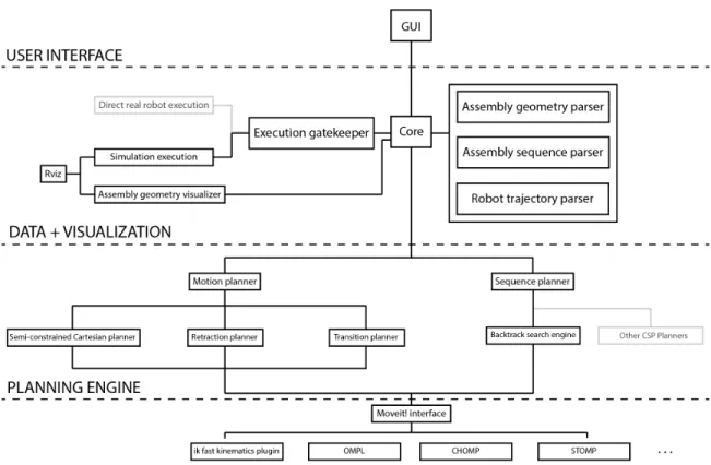
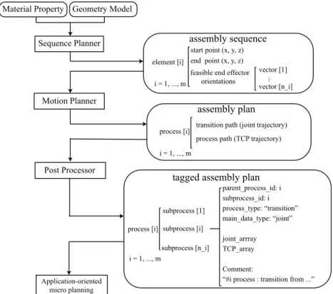
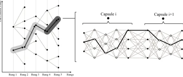
To harness the computational and engineering challenges posed by the assembly planning problem, this thesis proposes a planning framework that uses a hierarchical task and motion planning approach. The proposed planning framework incorporates three key modules as shown in figure 2-1. Instead of searching for a solution con-sidering all parts of the searching tree at once, the proposed approach identifies and breaks the problem into two key sub-problems, sequence planning and motion plan-ning, and isolates the sub-problems. First, the sequence planner (section 2.3) takes a discrete structure as input and outputs the assembly sequence and associated fea-sible end effector directions. The generation of assembly sequence and pruned end effector directions cuts the sequence-dependent ties between the sequence and motion planning subproblems, narrows down the searching space, and thus enables efficient solution searching. Next, with fixed assembly sequence and focused end effector di-rections, the motion planner (section 2.4) finalizes the choice of end effector pose for each assembly and plans for the robot’s entire joint trajectory during and between assemblies. Finally, the post processor (section 2.5) tags the computed trajectory plan with associated assembly information and outputs a complete assembly plan. After the framework is completed, it is possible for the user to insert more fine-tuned detail related to their application and hardware setup through the tagging system added by the post processor.
These modules, along with the framework inputs and outputs, are described in greater detail in the following sections. An example problem of using fixed-base
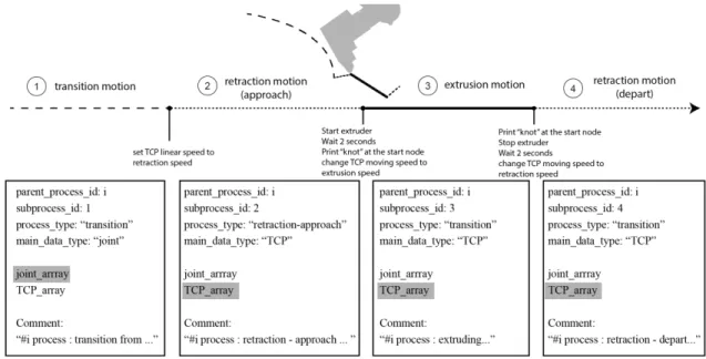
six-assembly sequence
element [i]
start point (x, y, z) end point (x, y, z) feasible end effector orientations vector [1] vector [n_i] i = 1, ..., m ... Sequence Planner Geometry Model Motion Planner Material Property Post Processor Application-oriented micro planning assembly plan
process [i] transition path (joint trajectory) process path (TCP trajectory)
i = 1, ..., m parent_process_id: i subprocess_id: i process_type: “transition” main_data_type: “joint” joint_arrray TCP_array Comment:
“#i process : transition from ...” i = 1, ..., m
tagged assembly plan
process [i]
subprocess [1]
subprocess [n_i] subprocess [i]
Figure 2-1: Overview of the assembly planning framework.
axis robot to spatially extrude a discretized linear frame structure is used to illustrate and exemplify the details of each module, but the system is general and can also apply to other robotic assembly tasks, for example, spatial positioning of discretized surfaces or volumetric elements.
Key assumptions In this thesis, the planning starts with an assembly plan skele-ton, or action sequence, that has a pre-defined repetitive pattern on the actions: for example, pick element 𝑜𝑖 from material rack - move - place element 𝑜𝑖 at position
𝑝𝑖 - move or extrude element 𝑜𝑖 at position 𝑝𝑖 - move. Only one fixed-base robot is
considered to be working on the assembly task, and the relative position between the machine and the assembly object is defined by users. There is no other constraint on the robot - it can has any degrees of freedom and any type of joint (rotational or prismatic). The planner needs to assign a correct order to assign object 𝑜𝑖 to each
action in the plan skeleton, and bind variables to fully specify robot’s configurations during and between assembly steps. The generated plan is purely geometric - it has
no time stamps assigned (so the speed of movement is unspecified) and does not take into account of any rigid body dynamics of the system [Giftthaler et al., 2017a]. The plan is generated completely offline before execution and it assumes the environment is deterministic, where the robot and the assembly will behave as specified in the plan. The robot is not equipped with any sensor ability during execution.
2.2 Model input
The assembly planning framework starts with an input 3D model from a designer. The model type is flexible, but should represent overall geometry, topology, and discretization for robotic assembly. Discretization can be performed by designer intu-ition or through an algorithmic meshing or decomposintu-ition approach; the framework is agnostic to how this step is carried out.
For the discretized linear frame structure, a standard node-member data repre-sentation is used. Nodes are described with 3D spatial coordinates in an indexed list, and linear members are described by their start and end node indices. In this way, the geometry and topology of the structure are efficiently described. Different cross sections and material properties could be assigned referring to specific member’s index.
In addition to the design model, users need to input the robot’s data that in-cludes the geometry of its links, limitation (min-max value) and type (rotational or prismatic) of its joints. Users also need to model and input static collision objects in the work environment, which are assumed to be invariant during the entire planning horizon. Relative position between the robot and the assembly object is set by a 3D translation vector.
2.3 Sequence planning module
In this module, a sequence planner takes any discrete geometry as input and solve for the order of the assembly operation and associated feasible end effector poses.
Globally, the sequence planner computes assignment of objects to each action in the predefined plan skeleton, which requires reasoning on the geometric and physical constraints in this combinatorial search. Locally in each assembly task, the planner resembles a grasp planner that computes all collision-free end effector poses, given all the collision objects in the target assembly stage.
This section first identifies the key constraints arisen in the sequence planning problem and formulates the problem as a Constraint Satisfaction Problem (CSP) (Section 2.3.1). Then, a solving technique is proposed to solve this CSP problem (Section 2.3.2), which embodies two main techniques: (1) user-guided model decom-position (2) backtracking search with 1-level forward checking and value ordering.
2.3.1 Problem formulation
The assembly sequence planning problem requires assigning every assembly action with an element from the model and find the geometric configuration of feasible end effector path1 for each action. Before introducing the sequence planning problem’s
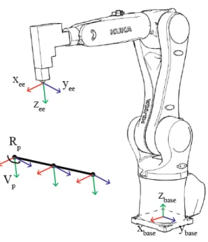
formulation, axis conventions are described in figure 2-2. The end effector frame is positioned at the 3D printing extruder’s tip. An end effector’s pose is defined by such a frame, which can be uniquely determined by (1) frame’s origin, (2) z-axis, and (3) rotation angle around the z-axis. Every trajectory point gets a local frame {𝑝} assigned to define the position and orientation of the end effector in that trajectory point. All of these coordinate frames are described in a common reference frame {𝑏𝑎𝑠𝑒}. In the following discussions, 𝑛 denotes the total number of elements to be assembled in the model.
The input frame model contains a set of linear elements, 𝑂1, . . . , 𝑂𝑛. Each element
specifies a linear trajectory that the end effector’s tip needs to traverse while extruding material. A discretized representation of the linear trajectory is used, which divides the trajectory into a sequence of points under certain discretization resolution. These
1In this thesis, the term path refers to a sequence of end effector poses. In general, a path is a
geometrical description of a robot’s configuration, which can be used to describe joint configuration [Siciliano et al., 2009].
Figure 2-2: End effector’s frame and trajectory point’s frame definition.
points only specify the end effector poses’ origins, which still have an infinite number of possible end effector’s orientation. In order to have a good printing result, the end effector is required to maintain its orientation when printing. Thus, the robot’s path for printing an element is determined by (1) point origins specified by the element’s linear path (2) orientation of the end effector.
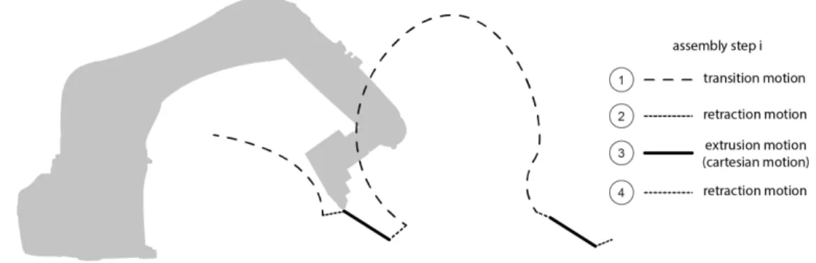
For spatial 3D printing of linear frame structure, only one assembly action type is considered: extrude. The sequence of assembly actions are defined in an alternating pattern: extruder-move-. . . -move-extrude. An important simplification is made to eliminate the move action concatenating adjacent extrude actions, which differs from general plan skeleton that couples the task-level reasoning with full geometric-level reasoning [Lozano-Pérez and Kaelbling, 2014]. In this way, the checking of transition paths’ existence is simplified to kinematics feasibility check and collision check during assembly. This simplification is equivalent to assume that if robot has a collision-free kinematic configuration at the start and the end of each assembly step, transition motion planner (2.4.3) can always find a feasible transition trajectory. This assump-tion can be found in many work in TAMP [Lagriffoul et al., 2014] and is generally valid through all of the performed experiments.
Each action in the predefined assembly plan skeleton is specified with a constraint variable and a set of geometric parameters. A constraint variable is a symbol that names an assembly element. A geometric parameter ranges over a continuous ge-ometric quantity that defines end effector’s pose. To bind these variables, a CSP planner is called to verify if the assembly plan skeleton is satisfiable. The correctness of an assembly plan skeleton is enforced by the constraints, which are expressed as relationships between assembled elements at each assembly step and end effectors’ pose during assembly.
To formulate a problem domain as a discrete constraint satisfaction problem (CSP), it is necessary to specify a set of constraint variables, a discrete domain of values for each variable, and a set of constraints. Constraints are specified by a set of variables to which they apply and a test function that maps an assignment of variable values to true or false [Dechter, 2003].
Constraint variables and geometric variables The CSP is encoded using con-straint variables 𝑂𝑖, 𝑖 = 1, . . . , 𝑛, which represent the assembly element assignment
for 𝑖th assembly action in the assembly action skeleton. Its value domain is 1, . . . , 𝑛, which represents the indices of elements in the input model.
Though not explicitly expressed as constraint variables, the geometric variables are pruned by the CSP solver and used to guide the solver’s search. The pruned geometric domains will be output as a part of the solution. Geometric variables used in this problem are 𝑉𝑖, 𝑖 = 1, . . . , 𝑛, which represent end effector’s direction for 𝑖-th
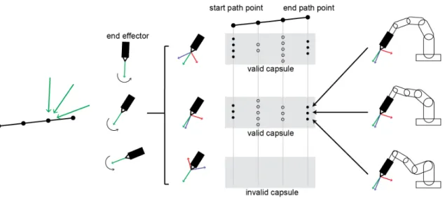
assembly action in the assembly action skeleton. Its value domain is 1, . . . , 𝑚 and represents the indices of directions. The indices of those directions are referencing an ordered list of unit vectors sampled on a semi-sphere. The sampling size 𝑚 is set according to desired discretization granularity. Thus, choice of end effector directions can be described by indices referencing to this shared list.
Notice that an assigned value 𝑣 of 𝑉𝑖 alone cannot uniquely determine the pose of
an end effector. One needs to determine rotation angle 𝑟 around the assigned direc-tion value 𝑣 to determine the end effector’s pose for assembly (see figure 2-2). This
degree of freedom remains undetermined during the entire sequence planning process and its determination is postponed until the motion planning process (Section 3.4). Notice that the domain definition of this rotation angle 𝑟 is application-dependent. While all the assembly task share a continuous rotation angle domain in interval [0, 2𝜋]for spatial extrusion due to the application and end effector’s z-axis symmetric nature, general assembly tasks, for example spatial positioning, might need different rotation angle domain 𝑟𝑖 to be assigned to each assembly element, depending on the
grasp relationship between end effector’s geometry and the target assembly element’s geometry.
Constraints Constraints relate the constraints variables to one another and restrain them to constant quantities. If all the constraints are collectively satisfiable, then an assembly plan skeleton is valid, and the pruned geometric variable domains specify the geometric details for subsequent motion planning. In the spatial printing domain, the following types of constraints are used:
AllDiff(𝑂1, . . . , 𝑂𝑛): Each assembly element is used only once by an assembly
action. No disassembling and reassembling is allowed. Thus all assembly element assignment 𝑂𝑖 ’s value is different.
Connectivity(𝑂1, . . . , 𝑂𝑘), 𝑘 = 1, . . . , 𝑛: At each assembly step, the newly added
element must be connected to existing structure or connected to the ground. Let Boolean matrix 𝐴 ∈ 𝑅𝑚*𝑚 denotes the adjacency matrix of the input spatial truss
design model:
𝐴[𝑖][𝑗] = ⎧ ⎨ ⎩
1, if element 𝑂𝑖 and 𝑂𝑗 share a node;
0, otherwise. And ground connectivity matrix 𝐺 ∈ 𝑅𝑚*1:
𝐺[𝑖] = ⎧ ⎨ ⎩
1, if element 𝑂𝑖 has a grounded node.
Then the connectivity constraint can be expressed as:
FORALL 1 <= 𝑖 <= 𝑚, EXIST 1 <= 𝑗 < 𝑖, 𝐴[𝑂𝑖][𝑂𝑗] = 1 OR 𝐺(𝑂𝑖) = 1
ExistValidEndEffectorPose(𝑆1, . . . , 𝑆𝑘), 𝑘 = 1, . . . , 𝑛: This constraint checks
if there exist a valid end effector pose for each assembly action in the assembly plan skeleton. At each assembly step, existing assembly elements 𝑂1, . . . , 𝑂𝑘−1 are
con-sidered as collision objects. These collision objects will collide with the end effector in some of the poses specified by direction 𝑉𝑖’s value and rotation angle around the
direction. 𝑉𝑖’s domain is pruned by the collision objects, eliminating the values that
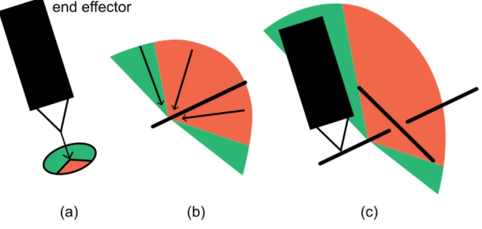
has no valid rotation angle. For spatial printing, a symmetric cone that encloses the end effector is used to avoid explicit check or sample all rotational values around the chosen direction. A graphical demonstration of this geometric pruning is shown in figure 2-3. This constraint can be expressed as:
FORALL 1 ≤ 𝑖 ≤ 𝑛, EXIST 𝑎, 1 ≤ 𝑎 ≤ 𝑚,
(FORALL 1 ≤ 𝑗 < 𝑖, 𝑇 [𝑂𝑖][𝑂𝑗][𝑎] = 1) AND (ExistValidKinematics(𝑎, 𝑂1, . . . , 𝑂𝑖−1, 𝑂𝑠𝑡𝑎𝑡𝑖𝑐))
where the three-dimensional matrix 𝑇 ∈ 𝑅𝑛*𝑛*𝑚:
𝑇 [𝑖][𝑗][𝑎] = ⎧ ⎪ ⎪ ⎪ ⎨ ⎪ ⎪ ⎪ ⎩
1, if printing element 𝑖 with direction 𝑎 does not collide with element 𝑗. 0, otherwise.
and ExistValidKinematics is a function that returns true if there exist one rotation angle around the chosen direction 𝑎 that enables whole-body kinematic solutions for the robot to traverse the path points of the current element, without colliding into already assembled object 𝑂1, . . . , 𝑂𝑖−1 and static world collision objects 𝑂𝑠𝑡𝑎𝑡𝑖𝑐, and
(a) (b) (c) end effector
Figure 2-3: Illustration of the geometric pruning. The existence of already assembled element (the element on the top in (c)) restricts the collision-free end effector pose in current assembly task, which prunes out values in associated end effector rotation angle 𝑅𝑖’s domain in (a) and direction 𝑉𝑖’s domain in (b). The green regions are the
valid region that does not collide with the collision objects.
angle in [0, 2𝜋] around direction 𝑎 and checking the existence of a feasible joint so-lution, until it finds the first soso-lution, and return true immediately or return false if it succeeds the sampling timeout without finding a feasible rotation angle. This function does not guarantee the existence of feasible kinematic solution for all the rotation angles - it is used only to eliminate the case where collision-free end effec-tor poses exist but without associated feasible kinematic solutions. Note that the computation involved in checking the end effector’s collision (FORALL 1 ≤ 𝑗 < 𝑖, 𝑇 [𝑂𝑖][𝑂𝑗][𝑎] = 1) is much lighter than checking the existence of a feasible kinematic
solution, thus might enable faster pruning in the search.
Stiffness(𝑆1, . . . , 𝑆𝑘), 𝑘 = 1, . . . , 𝑛: The stiffness constraint makes sure that the
partial assembly at each assembly step is stiff and the maximal deformation due to gravity (or other constantly presented load) is bounded by a predefined tolerance. In the case of spatial 3D printing, the deformation of all the nodes can be calculated using finite element analysis. The constraint test function returns true if the maximal node deformation is smaller than the tolerance. Otherwise, it returns false.
Stability(𝑆1, . . . , 𝑆𝑘), 𝑘 = 1, . . . , 𝑛: The stability constraint checker returns true
if the gravitational center’s projection on the supporting plane lies in the convex hull of all the grounded nodes, and returns false otherwise. It guarantees that the partially
assembled structure does not tip over as a rigid body.
Notice that for different type of discrete structure’s assembly, masonry vault’s assembly for example, since the mechanics involved is completely different to the one in spatial trusses, a different evaluation scheme for checking stability constraint can be added to check the static equilibrium of the partial assembly structure [Deuss et al., 2014,Livesley, 1992]. Also notice that the stability constraint and stiffness constraint are rarely encountered in classic constraint processing problems. To date, no existing techniques can efficiently evaluate this type of constraint in the CSP framework. The evaluation of the stability constraint commonly induce a large amount of overhead as they will be called many times by the CSP planner. Finding an efficient constraint encoding to accelerate computation speed is currently in the author’s investigation.
2.3.2 Solving the CSP
One key advantage of a CSP formulation is that it reduces our job to picking vari-ables and constraints to represent the problem, and use a generic solver to do the search. It is generally easier to articulate and check constraints for a given assign-ment of the variables than to construct a problem-specific search strategy, which is particularly important for the variety of problems emerging in architectural assembly. However, although in general efficient representations of the variables and constraints are preferred, as they will be called many times by the solver, the ExistValidEndEf-fectorPose, Stiffness and Stability constraints described in the last section is usually significantly non-linear and impossible to find an analytical expression. A simple backtracking search with 1-level forward checking and dynamic variable ordering is proposed in this work as a baseline solver to the assembly sequencing problem. In addition, to limit the computation in a reasonable amount of time, an additional user-guided task decomposition is introduced before running the search algorithm. More in-depth investigation of more efficient formulation of constraints and the use of more advanced CSP solving strategies are left for future research.
User-guided model decomposition Model decomposition involves grouping the discrete input model into several connected components. Taking advantage of user’s intuition on the geometric relationship, the decomposition breaks the whole assembly sequencing problem into several smaller ones, and then searching is confined in each of these small sub-problems, which scales down the size of the search space and leads to more efficient CSP solving in each component.
Existing automatic model decomposition techniques in the literature only demon-strate the ability to handle the decomposition of the surface mesh. Huang et al. developed a constrained graph decomposition method to iteratively decompose an input frame model into connected groups, while guaranteeing the physical stability of the group that is connected to the ground at each graph cut iteration [Huang et al., 2016]. However, this method uses elements’ height and mutual collision relationship as graph cut’s cost heuristic and only performs well with surface mesh. For models with a volumetric geometric feature, such as spatial lattices, it usually fails to scale down the search space in subgroups with evenly distributed element number.
Thus, in order to accelerate the computation for model with a large number of elements, the planning framework offers users the choice to manually group the ele-ments to guide the search in CSP, based on their intuition on the geometric occlusion between the decomposed groups. This process can be easily done on standard 3D modeling software. The resulting decomposition has been proven to be effective in handling the task planning for many geometry instances that have not been shown feasible to be 3D printed by a robot in existing literature (see chapter 3). A more general automatic model decomposition is currently under investigation by the au-thors.
Backtracking search with 1-level forward checking and dynamic variable ordering A backtracking search with dynamic variable ordering is applied to solve the CSP problem (chapter 5.3, [Dechter, 2003]). A domain-dependent heuristic is proposed to assist the variable ordering. Similar to the searching cost used in [Huang et al., 2016], a weighted-sum of three types of costs is used:
![Figure 2-7: Transition planning with different planners: (a) STOMP [Kalakrishnan et al., 2011] (b) CHOMP [Ratliff et al., 2009] (c) RRT* [Karaman and Frazzoli, 2011]](https://thumb-eu.123doks.com/thumbv2/123doknet/14130002.468974/52.918.161.758.526.754/transition-planning-different-planners-kalakrishnan-ratliff-karaman-frazzoli.webp)