Area-Schedule Based Design of High
Pressure Recovery Radial Diffusion Systems
The MIT Faculty has made this article openly available.
Please share
how this access benefits you. Your story matters.
Citation
Gao, Ruhou, Zoltán Spakovszky, Daniel Rusch, and René Hunziker.
“Area-Schedule Based Design of High Pressure Recovery Radial
Diffusion Systems.” Volume 2D: Turbomachinery (June 13, 2016).
As Published
http://dx.doi.org/10.1115/GT2016-57044
Publisher
ASME International
Version
Final published version
Citable link
http://hdl.handle.net/1721.1/116101
Terms of Use
Article is made available in accordance with the publisher's
policy and may be subject to US copyright law. Please refer to the
publisher's site for terms of use.
AREA
-SCHEDULE BASED DESIGN OF
HIGH PRESSURE RECOVERY RADIAL DIFFUSION SYSTEMS
Ruhou Gao, Zoltán Spakovszky
Gas Turbine Laboratory Massachusetts Institute of Technology
Cambridge, MA 02139
Daniel Rusch, René Hunziker
Compressor Development ABB Turbo Systems Ltd.
Baden, Switzerland
ABSTRACT
High-pressure ratio centrifugal compressors require advanced diffusion systems to achieve enhanced efficiencies set by future turbocharger applications. To address the shortcomings of the commonly used channel diffuser and airfoil cascade design perspectives, a streamtube based area-schedule is adopted paying special attention to the diffuser entry region. It is shown that the diffusion in the semi-vaneless-space, controlled chiefly by inlet flow angle and the vane suction side geometry, plays a key role in improving diffuser performance. Removing excess thickness from the suction side eliminates flow overspeed, increases effective diffusion length, and leads to higher pressure recovery at reduced stagnation pressure loss. The pressure side thickness distribution controls the channel area schedule. Thin leading edges ensure smooth flow area transition into the channel and reduce the vane upstream influence, mitigating high-cycle fatigue related mechanical issues.
NOMENCLATURE
A flow area
Ath diffuser total throat area
AR area ratio
𝐶𝑝 pressure recovery coefficient
𝐶𝑝,𝑖 ideal pressure recovery coefficient
𝐶𝑝,𝑡 stagnation pressure loss coefficient CFD Computational Fluid Dynamics HCF High Cycle Fatigue
LE vane leading edge
M Mach number
RANS Reynolds Averaged Navier Stokes SVLS semi-vaneless space
T static temperature 𝑇𝑡 stagnation temperature TE vane trailing edge 𝑉𝜃 tangential velocity 𝑉𝑟 radial velocity VLS vaneless space a semi-major axis b semi-minor axis c vane chord
m location of maximum thickness p static pressure
𝑝𝑡 stagnation pressure ps vane pressure side r radius
s span
ss vane suction side x distance along the chord y+ dimensionless wall distance
α flow angle
ε eccentricity
𝜀𝐷 diffuser effectiveness η efficiency
λ volute inlet swirl parameter
σ standard deviation
INTRODUCTION
The complex nature of the impeller outflow presents multiple challenges for the downstream vaned diffuser. More specifically, the impact of flow angle, Mach number, flow non-uniformity and unsteadiness on diffuser performance was investigated in a companion paper [1]. It was demonstrated through computations and experiment, that diffuser performance in terms of effectiveness, which describes the pressure recovery obtained relative to the maximum possible pressure rise, correlates well with the mixed-out averaged impeller outflow angle. It was also shown that, due to strong mixing processes in the diffuser inlet region, effectiveness is largely independent of the time-averaged spanwise and unsteady pitchwise non-uniformity from the impeller. Based on this, careful consideration must be given in the design process to the diffuser inlet region and, from a practical perspective, simplified, isolated diffuser calculations can be adopted given proper definition of the inflow conditions. This is the focus of the present paper.
Proceedings of ASME Turbo Expo 2016: Turbomachinery Technical Conference and Exposition GT2016 June 13 – 17, 2016, Seoul, South Korea
There are two commonly used design approaches for radial vaned diffusers: the channel diffuser approach and the airfoil (cascade) based approach. Extensive databases in the literature exist for both (see for example [2, 3, 4, 5]) and have been used with success. There is however a lack of first principles based design guidelines which could possibly break new ground in further advancing diffuser performance. The former approach considers the radial vaned diffuser to be similar to a straight-walled channel diffuser. The best design is achieved where a balance is struck between the length-to-width ratio and the area ratio. The challenge is that the vane inlet and exit metal angles are important in impeller and volute matching but are not accounted for. Also, there is a lack of consistency in the definition of diffuser area ratio which is complicated by the geometry of the semi-bounded space in the diffuser entry region, commonly denoted as the semi-vaneless space.
FIGURE 1. Meridional view of centrifugal compressor
An alternative perspective is the airfoil cascade approach which uses a conformal transformation of linear cascade data into the radial plane [6]. While the metal angles are well defined for component matching, estimating stagnation pressure loss becomes a challenging task because the linear cascade data does not account for the increase in area with radius. Put another way, a separation-free linear cascade design might cause severe separation after conformal transformation. To account for this, typically a factor of seven or eight in loss coefficient is recommended when estimating stagnation pressure loss using linear cascade data [4]. Lastly, both channel diffuser and airfoil cascade design approaches neglect the strong mixing and diffusion in the vaneless and the semi-vaneless space which, as will be shown, are key design considerations.
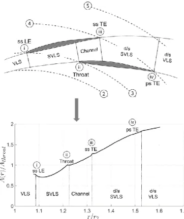
FIGURE 2. Illustration of a typical vaned diffuser and its
subcomponents (top) and flow area distribution as a function of radius (bottom) – note flow acceleration and therefore reduced diffusion in semi-vaneless space (SVLS).
The centrifugal compressor investigated here is a 5.0 pressure ratio, high-speed compressor of advanced design with an impeller blade Mach number of 1.54. As sketched in Fig. 1 the test article consists of an impeller and a vaned diffuser (together called the stage) and a volute. The impeller contains 9 main and 9 splitter blades with backsweep, and the vaned diffuser consists of 17 aerodynamically profiled vanes. In the blade-to-blade domain the vaned diffuser can be divided into the following five subcomponents, as shown in Fig. 2: (1) vaneless space (VLS): unbounded flow path where diffusion is mainly set by endwall contour (pinch) and impeller exit flow angle, (2) semi-vaneless space (SVLS): semi-bounded flow path where diffusion is mainly governed by the vane suction side geometry, (3) channel: diffusion is mainly set by area ratio and length-to-width ratio, following classical channel diffuser guidelines, (4) downstream SVLS: diffusion is mainly set by vane exit angle and vane pressure side, and (5) downstream VLS: diffusion is mainly set by swirl angle and radius ratio.
Given the impeller outflow angle, endwall contour, and profiled vane diffuser geometry1 the area schedule can be
calculated and is shown in Fig. 2 on the bottom. The suction side of the vane near the leading edge, set by the camberline
1 From here on this diffuser geometry will be referred to as the baseline diffuser.
and thickness distribution, decreases the flow area in the SVLS and leads to flow acceleration, reducing diffusion and effective diffuser length and yielding flow separation and reduced pressure recovery.
SCOPE OF PAPER
In the quest of identifying a vane geometry with significantly improved performance, the idea is to adopt a streamtube perspective and to define the vane suction and pressure sides by a carefully scheduled flow area distribution that maximizes diffusion while keeping stagnation pressure loss at a minimum. Special attention is given to the diffuser entry region, with consideration of mixing and high diffusion in the vaneless and semi-vaneless space. The objective is to determine the best area schedule, and therefore vane geometry, given properly averaged impeller exit conditions. More specifically the paper addresses the following research questions:
1. For a given impeller outflow and infinitely thin vanes, what is the ideal diffuser performance and corresponding area schedule?
2. Given this ideal diffusion path, what thickness distribution yields minimum impact on performance while meeting structural requirements?
3. What is the impact of such an improved diffuser design on impeller and volute performance?
The investigation begins with the assumption that zero-thickness vanes yield the best performance. This assumption will be verified later. Further, it will be shown in both computations and full-scale compressor experiments that aft-thickened vanes, defined by a smooth and continuous area schedule with high loading in the semi-vaneless space (see Fig. 3) yield close to a doubling in the ratio of pressure recovery over stagnation pressure loss. A shorter vaneless space, enabled by thin vane leading edges, avoids flow acceleration and improves diffusion in the semi-vaneless space. The closer spaced diffuser vanes increase impeller efficiency by 0.8 percentage points while almost halving the upstream influence. The aim of the paper is to lay out step by step the general process and guidelines by which vaned diffuser performance is improved. Implications on the matching of upstream and downstream components, such as the volute, are also discussed.
TECHNICAL APPROACH
The same impeller and diffuser endwall contour, including pinch, were used throughout this study. All investigations were carried at impeller design speed and the diffuser throat area was maintained for all geometries so as to keep the same flow capacity [7]. Furthermore, the diffuser inlet metal angles were matched to the impeller outflow at zero incidence2.
2 A one-dimensional compressible channel flow model was used in the vaneless space. A detailed description can be found in [9].
FIGURE 3. Aft-thickened vaned diffuser geometry defined by an
ideal area schedule and high loading in the semi-vaneless space.
First, zero-thickness vaned diffusers, so called camberline diffusers were defined and assessed in a parametric study to identify the ideal diffusion path, characterized by diffuser inlet and exit radius ratios and vane turning angle, 𝛼4− 𝛼3. Next,
the vane profile thickness distribution and leading edge geometry were systematically varied to assess their impact on diffuser performance. Finally, the calculations were compared and validated with full-scale compressor experiments.
Three different diffuser designs using the area scheduling approach were assessed in a turbocharger compressor test facility at ABB Turbo Systems Ltd. The stage performance was calculated by a proprietary meanline data reduction scheme. The diffuser subcomponent performance was dissected using an array of pressure taps located on the shroud side endwall.
Steady impeller-diffuser RANS calculations were performed in NUMECA FINE/Turbo using the same setup as in [1]. For a single passage calculation, typical node numbers for the impeller and the diffuser meshes were 1.4 and 0.4 million respectively. The Spalart-Allmaras turbulence model was used with y+ values maintained between 1 and 10. All calculations were performed at standard day +10° C conditions. The flow conditions at diffuser inlet, r21, and exit, r41, were extracted at a
distance of 7.5% and 52% of impeller exit radius respectively. Mixed-out averaged flow conditions were used in the assessment and show good agreement with the time and area averaged flow conditions obtained in the experiments.
Compression system performance was assessed via machine isentropic efficiency. To characterize vaned diffuser
performance, static pressure recovery and total pressure loss coefficients were defined as:
𝐶𝑝= 𝑝5−𝑝2 𝑝𝑡2−𝑝2 , (1) 𝐶𝑝,𝑡= 𝑝𝑡2−𝑝𝑡5 𝑝𝑡2−𝑝2 . (2)
Similar to the lift-to-drag ratio, a unified diffuser performance parameter can be defined as:
𝐶𝑝
𝐶𝑝,𝑡=
𝑝5−𝑝2
𝑝𝑡2−𝑝𝑡5 . (3)
To decouple the impact of diffuser inlet Mach number, it is useful to also define effectiveness, which relates actual diffuser 𝐶𝑝 to the isentropic pressure recovery, 𝐶𝑝,𝑖,
𝜀𝐷 = 𝐶𝑝
𝐶𝑝,𝑖 . (4)
With a little algebra the unified diffuser performance parameter and effectiveness can be related via the diffuser exit Mach number: 𝜀𝐷= [1 + 𝐶𝑝,𝑡 𝐶𝑝 (1 + 𝛾−1 2 𝑀5 2) −𝛾 𝛾−1 ] −1 . (5)
Since 𝑀5= 𝑀5(𝑀2, 𝐴𝑅) , effectiveness is appropriate
when comparing diffusers with the same area ratio. When area ratio is a design parameter, diffusers optimized based on 𝜀𝐷 will
in general yield lower area ratio and higher residual kinetic energy compared to an optimized design based on Cp/Cp,t
because of the effect of density change through the diffuser at higher Mach number.
On the other hand, when comparing diffusers with different area ratios for a fixed diffuser inlet Mach number, the appropriate diffuser performance parameter is Cp/Cp,t.
Depending on the design context, both performance metrics are used in this work.
IDEAL DIFFUSION PATH
A series of candidate zero-thickness diffusers were designed with circular leading and trailing edges, and a thin3
and constant thickness distribution with the aim to establish the link between area ratio and non-dimensional diffusion length. In the vaned diffuser design context, the area ratio is controlled by the turning angle, which is the difference between inlet and outlet metal angles, 𝛼4− 𝛼3. The diffuser exit radius ratio,
𝑟4/𝑟2, mainly characterizes the non-dimensional diffusion
length. The effect of impeller-diffuser spacing on diffuser performance is investigated by varying the diffuser inlet radius
3 In the calculations the thickness-to-chord ratio was 1e-6, effectively removing the effect of thickness distribution on flow area.
ratio, 𝑟3/𝑟2. The impact of these three design parameters on
diffuser area schedule is schematically illustrated in Fig. 4.
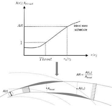
FIGURE 4. For a given impeller geometry and fixed throat area, the
diffuser area schedule is altered via changes in diffuser inlet and outlet radius ratios and turning.
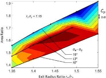
Based on this a total of 43 different geometries were assessed using steady stage calculations. Following the format of a typical Reneau chart the pressure recovery is assessed as a function of area ratio4 and non-dimensional diffusion length in
terms of r4/r2 in Fig. 5.
FIGURE 5. Static pressure recovery 𝐶𝑝 of camberline diffusers with
𝑟3/𝑟2= 1.15. Highest pressure recovery observed for 13° turning.
The lines of constant turning angles (similar to the divergence angle 2𝜃 in a Reneau chart) are also identified. Maximum 𝐶𝑝is
achieved for 1.4 < 𝑟4/𝑟2< 1.5 and 𝐴𝑅 ≈ 1.6 which is lower
than the best AR of 2 and L/W of 8 in a typical Reneau chart. Large increases in flow area and high turning angles at low exit radius ratios can lead to endwall separation reducing the effective flow area and therefore diffusion. In contrast, the stagnation pressure loss coefficient in Fig. 6 increases monotonically with exit radius ratio, as profile loss and the
4 In Figs. 5–7, 10-11 area ratio is defined as A(r
extent of corner separations scale with vane surface area. Without considering the volute the ideal diffuser area schedule is identified by the ratio of the two parameters, Cp/Cpt, in Fig. 7
for 𝑟4/𝑟2≈ 1.4 and 𝐴𝑅 ≈ 1.45.
FIGURE 6. Stagnation pressure loss 𝐶𝑝,𝑡 of camberline diffusers
with 𝑟3/𝑟2= 1.15. Diffusers with short diffusion path and moderate
area ratio yield lowest loss.
FIGURE 7. Performance parameter 𝐶𝑝/𝐶𝑝,𝑡 of camberline diffusers
with 𝑟3/𝑟2= 1.15.
To characterize the effect of inlet radius ratio on diffuser performance, four different diffuser designs with the same optimum turning angle, area ratio, and chord length were assessed. The comparison in Fig. 8 indicates that closer spaced diffusers improve diffuser performance. For typical transonic and high swirl impeller exit conditions the one-dimensional compressible vaneless space flow model [9] suggests a drop in pressure rise upstream of the semi-vaneless space. In agreement with [1] a closer spaced semi-vaneless space increases the diffuser inlet Mach number and therefore improves diffuser pressure recovery. This also enables a more compact stage design where the desired area ratio can be achieved at a lower exit radius ratio and with a smoother area schedule as shown in
Fig. 9. The minimum impeller-diffuser spacing is constrained by mechanical considerations such impeller high-cycle-fatigue (HCF). To facilitate closer spacing of non-zero thickness vanes, the vane upstream influence must be reduced which will be discussed in detail later.
FIGURE 8. Strong dependence of diffuser performance parameter
𝐶𝑝/𝐶𝑝,𝑡 on diffuser inlet radius ratio governed by diffusion in SVLS.
FIGURE 9. A closer spaced semi-vaneless space improves diffusion
and achieves the desired area ratio at lower exit radius ratio. VOLUTE MATCHING
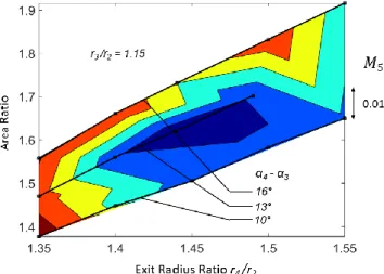
Before considering the effects of vane thickness it is important to characterize the impact of the diffuser exit conditions on volute performance. To achieve a performance improvement on the overall diffusion system level, the diffuser performance charts must be matched to the volute characteristics. Assuming the downstream vaneless space is long enough such that volute is aerodynamically decoupled, a one-dimensional volute model based on diffuser exit conditions can be used to estimate the system level performance. The volute inlet swirl parameter, = v/vr, and the volute inlet
Mach number have the strongest influence on volute performance. The impact of diffuser geometry on these two parameters is depicted in Figs. 10 and 11. The region of minimum Mach number overlaps with the region of maximum 𝐶𝑝 in Fig. 5 and the lowest volute inlet swirl parameter is
observed in the same region, causing a more radial flow into the volute. As suggested by typical one-dimensional volute loss
models [4], a lower volute inlet swirl parameter yields higher radial kinetic energy loss in the volute, decreasing volute performance. For a fixed endwall contour the impact of volute inlet Mach number must therefore be carefully balanced by that of the inlet swirl parameter. While the minimum diffuser exit Mach number is set by diffuser pressure recovery, the system performance can be further improved by profiling the diffuser exit endwall to facilitate a near optimum volute inlet swirl parameter.
FIGURE 10. Exit Mach number of camberline diffusers with 𝑟3/𝑟2=
1.15. Minimum exit Mach number coincides with maximum 𝐶𝑝 in Fig.
5.
FIGURE 11. Mixed-out volute inlet swirl parameter 𝜆 of camberline
diffusers with 𝑟3/𝑟2= 1.15. Lowest exit swirl parameter coincides
with highest 𝐶𝑝 in Fig. 5.
EFFECT OF VANE THICKNESS DISTRIBUTION
Diffuser performance is sensitive to the suction side geometry because of its strong impact on the area schedule in the semi-vaneless space. The pressure side, on the other hand, has no impact on flow area up until the diffuser channel. By adopting the ideal camberline as the suction side of the profiled diffuser with non-zero thickness, the SVLS area schedule can be matched to that of the ideal camberline diffuser. To
investigate the effect of the channel area schedule on diffuser performance, two different diffuser geometries were assessed using steady RANS calculations. The so-called front-thickened diffuser is a profiled diffuser with the suction side adopted from the ideal camberline diffuser and the pressure side formed by adding the thickness distribution of a controlled diffusion airfoil. The thickness distribution of a NACA SC(2)-1006 supercritical airfoil was chosen for this study. In contrast, the aft-thickened diffuser has the same suction side, but the majority of the vane thickness is introduced at higher radii. The thickness distribution of the aft-thickened diffuser was prescribed by a Gaussian distribution
𝐺(𝑥) = 𝑒−12( 𝑥−𝑚
𝜎 ) 2
, (6)
where 𝑚 is the location of maximum thickness, and depends on the leading edge thickness. Profiled diffusers with Gaussian thickness distributions will be referred to as G-series diffusers. Figure 12 compares the thickness distributions and the vane geometries of the front and aft-thickened diffusers.
FIGURE 12. Top: normalized profile thickness distribution, front vs.
aft-thickened vanes – the aft-thickened profile distribution removes thickness in the semi-vaneless space and instead of a thick leading edge thin, elliptical leading edges are used (not shown here). Bottom: front vs. aft-thickened vane geometries – controlled diffusion vs. Gaussian diffusion (G-series).
The area schedule of the front and aft-thickened diffusers are compared to the ideal camberline diffuser in Fig. 13. The area schedules in the semi-vaneless space are nearly identical to that of the ideal camberline diffuser but at diffuser channel inlet, the front-thickened vane experiences a sudden area
reduction due to the thick leading edge. In contrast, the aft-thickened vane yields a smoother area transition.
FIGURE 13. Comparison of area schedule of the front vs.
aft-thickened vanes.
FIGURE 14. Performance parameter 𝐶𝑝/𝐶𝑝,𝑡 of front and
aft-thickened diffuser compared to the baseline and the ideal camberline diffusers.
The performance parameter 𝐶𝑝/𝐶𝑝,𝑡 of both diffusers and
that of the baseline and the ideal camberline diffusers are computed in Fig. 14. In the case of the front-thickened diffuser, peak performance is noticeably shifted towards the choke side because for a constant throat area, thickness near the leading edge effectively increases the inlet metal angle towards the radial direction (and thus the flow angle at minimum stagnation pressure loss). This effect is reduced for the aft-thickened diffuser and compared to the baseline diffuser and the front-thickened diffusers with thick leading edges, the aft-front-thickened diffuser yields characteristics with a distinguished peak. Albeit the undesirable mismatch, there is a marked improvement in performance associated with area scheduling. Eliminating the area reduction in the semi-vaneless space leads to significant performance improvements in both front and aft-thickened diffusers. Furthermore, by smoothly scheduling the flow area into the diffuser channel, the aft-thickened diffuser performance approaches that of the ideal camberline diffuser.
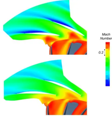
Returning to the ideal diffuser charts, the elimination of the area reduction in the semi-vaneless space in the G-series diffusers yields increased effective diffusion length at a given area ratio. This reduces the corner separation as observed in Fig. 15.
FIGURE 15. Mach number contours at mid-span at design mass flow:
baseline (top) vs. aft-thickened G-series diffuser (bottom).
FIGURE 16. Comparison of diffuser geometries with different leading
edge thicknesses.
EFFECT OF VANE LEADING EDGE SHAPE
To assess the impact of vane leading edge thickness on diffuser performance, three diffusers with comparable overall design parameters ( 𝑟3/𝑟2, 𝑟4/𝑟2 and AR) but different leading
edge shape, with an eccentricity5 of 0.95, was used in all cases.
The leading edges were blended into the main vane section ensuring a continuous first derivative of the metal angle at the blending point. The three leading edge geometries are depicted in Fig. 16.
Since the three diffuser geometries have comparable area ratios, effectiveness is the more appropriate metric for performance comparison as it bookkeeps the changes in diffuser inlet Mach number. As shown in Fig. 17, increased leading edge thickness markedly reduces diffuser effectiveness. From an area schedule perspective, the leading edge thickness is directly linked to the diffuser channel flow area schedule. A thicker leading edge leads to a larger flow area reduction at the channel inlet, which causes flow acceleration and decreased pressure recovery.
Vanes with thinner forward portions might be prone to blade wake-induced vibrations. However, the diffuser vanes considered here are clamped between the two diffuser endwall plates so that the vane natural frequencies are relatively high and the vibrational stress levels low. A detailed FEM analysis is required to further assess this but, based on experience in diffuser mechanical design, it is conceivable hat the forward vane portion can be made substantially thinner than current state of the art.
FIGURE 17. Impact of diffuser leading edge thickness on diffuser
effectiveness. Thicker leading edges lead to more pronounced area reduction at diffuser channel inlet, reducing diffuser effectiveness. EXPERIMENTAL ASSESSMENT
Two different G-series diffusers and the baseline diffuser were assessed experimentally in full-scale compressor tests. The measurements were post-processed using a proprietary mean-line data reduction scheme to calculate conditions through the compressors. The maximum measurement errors, to within 95% confidence levels, are ≤ ±1.0% for flow rate, ≤
5 Eccentricity is defined as 𝜀 = √1 − (𝑏/𝑎)2, where 𝑎 and 𝑏 are the
semi-major and semi-minor axes of the ellipse.
±0.2% for total pressure ratio, and ≤ ±0.5% for efficiency. The design parameters are summarized in Tab. 1. While the G designation originated from the Gaussian thickness distribution, the number designation is only chronological and has no other significance. The G5 diffuser was designed based on comparable overall design parameters ( 𝑟3/𝑟2, 𝑟4/𝑟2 and AR)
but different leading edge radii. The G7 diffuser was designed to assess the effect of higher inlet radius ratio and shorter downstream vaneless space on diffuser performance. The same volute at 𝑟5/𝑟2= 1.63 was used for all diffusers tested.
TABLE 1. Design parameters of experimentally tested diffusers
Design r3 /r2 r4/r2 AR rLE /c r5/r2 r5/r4
Baseline 1.15 1.40 1.52 N/A 1.63 1.16 G5 1.15 1.44 1.44 0.008 1.63 1.13 G7 1.225 1.50 1.44 0.008 1.63 1.08
FIGURE 18. Illustration of common diffuser measurement plate
instrumentation used to assess diffuser subcomponent performance.
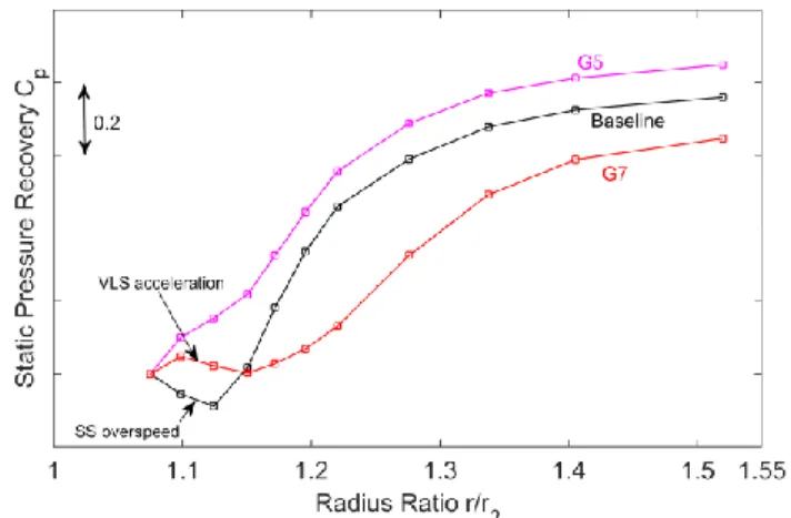
FIGURE 19. Measured diffuser channel static pressure rise for
baseline, G5, and G7 diffusers. The SVLS of the G5 diffuser provides 12% improvement of overall pressure recovery relative to the baseline diffuser.
Figure 18 illustrates the fixed static pressure tap array overlaid with the three different test diffusers. The pressure is pitchwise averaged at diffuser inlet, vane leading edge radius, throat, and vane trailing edge radius (stations 21, 3, 3t, and 4 respectively). The mid-channel pressure recovery is measured by pressure taps located on the channel centerline from station 21 to 41. The diffuser exit conditions for the G7 diffuser cannot be accurately assessed because the pressure at the diffuser exit radius cannot be pitchwise averaged. Hence, only the mid-channel pressure recovery characteristic is shown for G7. The diffuser static pressure recovery along the diffusion path is shown in Fig. 19. The same trend is observed as predicted by the area schedule plots. The flow area reduction in the semi-vaneless space of the baseline diffuser accelerates the flow. Similarly, the area reduction in the vaneless space of the G7 diffuser generates high profile loss with little diffusion. As more kinetic energy is dissipated in the vaneless space, the diffuser inlet Mach number decreases yielding less pressure recovery. The smooth diffusion path, combined with a higher diffuser inlet Mach number, improves the pressure recovery of the G5 diffuser compared to the baseline diffuser.
Since the baseline and the G-series diffusers have different area ratios, the diffuser performance parameter 𝐶𝑝/𝐶𝑝,𝑡 is used
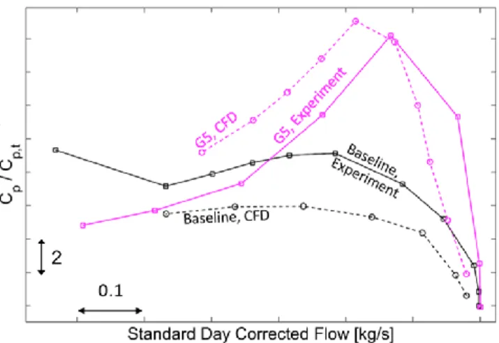
to compare diffuser performance. The trends of the mixed-out averaged calculations in Fig. 20 show good agreement with the experimental results and the G5 diffuser demonstrates a 1.8 fold improvement in 𝐶𝑝/𝐶𝑝,𝑡 relative to the baseline case.
FIGURE 20. Comparison of baseline vs. G5 diffuser performance
parameter 𝐶𝑝/𝐶𝑝,𝑡: the baseline RANS calculation over-predicts
separation and therefore under-predicts 𝐶𝑝/𝐶𝑝,𝑡.
The thin leading edge of the G5 diffuser impacts the range of improved diffuser performance. The performance drops back to baseline levels at off-design conditions. This is in agreement with the impeller exit pitchwise unsteady incidence variation observed in [1]. However, the surge margin is maintained, and a better overall performance is achieved.
In summary, for matched inlet flow angles 6 profile
thickness inevitably causes the diffuser area schedule to deviate from ideal. To avoid undesirable flow area reduction, the idea behind the aft-thickened G-series diffuser is to shift the thickness to higher radii such that maximum diffusion can be achieved in the semi-vaneless space.
DIFFUSION SYSTEM COMPONENT INTERACTION
In addition to mechanical challenges, strong pitchwise static pressure variation at impeller exit can lead to decreased impeller performance [8]. The pitchwise static pressure variation due to vane upstream influence can be defined as
𝑝(𝜃) ̅̅̅̅̅̅̅−𝑝̿̿̿̿̿21
𝑝𝑡,21
̿̿̿̿̿̿̿−𝑝̿̿̿̿̿21 , (7)
where 𝑝̿̿̿̿ and 𝑝21 ̿̿̿̿̿̿ are time and pitchwise averaged static and 𝑡,21
total pressures at station 21, and 𝑝(𝜃)̅̅̅̅̅̅ is the time averaged local static pressure.
FIGURE 21. Pitchwise static pressure variation near baseline diffuser
inlet. Pressure tap locations are marked by black circles. Linear interpolation used for missing pressure tap (marked by red dot).
FIGURE 22. Pitchwise static pressure variation near G5 diffuser inlet.
6 The diffuser inlet metal angles were matched to the impeller outflow at zero incidence which, as will be shown, occurs at lower corrected flow than peak diffuser performance. This leads to a mismatch between impeller and diffuser and can be corrected in a second design iteration.
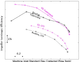
The vane upstream pressure variations were extracted from the stage RANS calculations and compared with the experimental results. The measurements are assumed periodic and are therefore repeated. The calculations for the baseline diffuser agree well with the experimental results in Fig. 21. For the G5 diffuser in Fig. 22 the peak-to-peak pressure variation is reduced by 42% at best diffuser efficiency. The reduced upstream influence can be attributed to the leading edge shape/thickness, as the thin leading edges in the G5 diffuser cause the detached bow shock in front of the vanes in the baseline diffuser to become attached oblique shocks. The reduced upstream influence mitigates impeller exit pressure non-uniformity, and thus improves impeller efficiency. Fig. 23 compares impeller efficiency between the baseline design and G5 diffuser. The mixed-out averaged calculation agrees in trend with the experimental data. As vane upstream influence attenuates, the impeller efficiency improves by 0.8 percentage points at the design condition relative to the baseline diffuser.
FIGURE 23. The G5 diffuser yields a 0.8% point improvement in
impeller efficiency relative to the baseline diffuser at design condition.
FIGURE 24. The G5 diffuser achieves a 0.74% point improvement in
stage efficiency relative to the baseline diffuser at design condition.
From a stage performance perspective the G5 diffuser achieves a 0.74% point improvement at design conditions relative to the baseline diffuser in Fig. 24. The measured efficiency improvement is less than that computed, which is suggested to be due to the over-predicted separation in the baseline diffuser calculations. This over-prediction is well documented in the literature [8, 9]. Fig. 25 illustrates the changes in diffusion system isentropic efficiency (including volute) compared to the stage efficiency. In addition to the impeller-diffuser mismatch, the volute contributes significantly to the loss relative to the stage only (dashed lines). The G5 diffuser has a shorter downstream vaneless space which, combined with a higher diffuser exit Mach number, is thought to negatively impact volute performance [9].
FIGURE 25. Stage efficiency compared to diffusion system efficiency
(volute included) at design condition: the higher exit Mach number of the G5 diffuser increases volute stagnation pressure loss.
FIGURE 26. Work coefficient and system total pressure ratio at
design condition.
To summarize, Fig. 26 illustrates the impact of the volute mismatch on the overall characteristics. The work coefficient is improved due to the reduced vane upstream influence while the overall pressure ratio remains about the same as the G5 diffuser performance benefits are neutralized by the increased volute
loss. Time and cost did not permit further experiments with a better matched volute. This is left for future work.
SUMMARY AND CONCLUSIONS
Both computations and experiments demonstrate that a smooth diffusion path, which avoids area reductions and discontinuities, is critical for improved diffuser performance. More specifically, the semi-vaneless space is the diffuser subcomponent that offers the highest potential for performance improvements by mitigating flow overspeed, reducing profile loss, and increasing effective diffusion length.
Based on the zero-thickness camberline diffuser study the ideal diffuser performance is set by diffuser area ratio and effective non-dimensional diffusion length, governed by the inlet and exit radius ratios and the flow turning angle. A large increase in flow area can lead to flow separation and reduce pressure recovery. Closer spaced diffuser vanes increase the inlet Mach number and therefore pressure recovery.
Adopting the ideal camberline as the suction side of the profiled diffuser ensures high pressure recovery at low stagnation pressure loss in the semi-vaneless space. Thin leading edges enable smooth flow area transition into the diffuser channel and reduce vane upstream influence, yielding higher channel pressure recovery as well as improved impeller efficiency.
The volute performance is hypothesized to be sensitive to both volute inlet swirl parameter and Mach number. A lower volute inlet Mach number is desirable and to achieve performance improvements on the overall diffusion system level, the volute needs to be carefully matched.
The area schedule based G-series diffusers demonstrate improved channel pressure recovery especially in the semi-vaneless space, where unwanted flow accelerations seen in the baseline diffuser are transformed into continuous diffusion. A 1.8 fold improvement in diffuser performance parameter 𝑪𝒑/𝑪𝒑,𝒕 was achieved. In addition, a 0.8% point increase in
impeller isentropic efficiency due to reduced vane upstream influence and a 0.74% point increase in stage efficiency were demonstrated.
ACKNOWLEDGMENTS
The authors would like to thank Professor Nick Cumpsty for the stimulating discussions and the anonymous reviewers for their useful and constructive comments. Their suggestions have improved the paper greatly. This research was funded by ABB Turbo System Ltd, which is gratefully acknowledged.
REFERENCES
[1] Everitt, J., Spakovskzy, Z., Rusch, D., and Schiffmann, J., "The role of impeller outflow conditions on the performance and stability of airfoil vaned radial diffusers," Paper GT2016-56168 in Proceedings of ASME Turbo Expo, Seoul, South Korea, 2016.
[2] Reneau, L., Johnston, J., and Kline, S., Performance and Design of Straight, Two-dimensional Diffusers, Stanford, California: Thermosciences Division, Dept. of Mechanical Engineering, Stanford University, 1964.
[3] Japikse, D., and Baines, N., Diffuser Design Technology, Norwich, VT: Concepts ETI, 1998.
[4] Japikse, D., Centrifugal Compressor Design and Performance, Wilder, VT: Concepts ETI, 1996.
[5] Horlock, J. H., Axial Flow Compressors, Fluid Mechanics and Thermodynamics, London: Butterworths Scientific Publications, 1958.
[6] Faulders, C., An aerodynamic investigation of vaned diffusers for centrifugal compressors, Tech. rep., MIT Gas Turbine Laboratory, Cambridge, Massachusetts, 1954. [7] Casey, M., and Rusch, D., "The matching of a vaned
diffuser with a radial compressor impeller and its effect on the stage performance," J. of Turbomach., vol. 136, 2014. [8] Murray, N., Effects of impeller-diffuser interaction on
centrifugal compressor performance, Master’s thesis, Massachusetts Institute of Technology, Department of Aeronautics and Astronautics, 2003.
[9] Gao, R., Area-schedule based design of high pressure recovery radial diffusion systems, Master’s thesis, Massachusetts Institute of Technology, Department of Aeronautics and Astronautics, 2015.