±Author to whom all correspondence should be addressed.
JO U R N A L O F M A T E R IA L S S C I E N C E : M A T E R I A L S I N ME D I C IN E 8 ( 19 9 7 ) 68 3 — 69 0
Surface activation of polyetheretherketone
(PEEK) and formation of calcium phosphate
coatings by precipitation
S. - W . H A *±, M . K I R C H * , F . B I R C H L E R * , K . - L . E CK E R T * , J . M A Y E R * ,
E . W I N T E R M A N T E L * , C . S I T T I Gt, I. PFUND-KLINGENFUSSt, M. TEXTORt, N . D . S P E N C E R°, M . G U E C HE V A°, H. V O N M O N T°
*
Chair of Biocompatible Materials Science and Engineering, Department of Materials,
ETH Zu¨rich, Wagistr. 23, 8952 Schlieren, Switzerland
t
Laboratory of Surface Science and Technology, Department of Materials,
ETH Zu¨rich, 8092 Zu¨rich, Switzerland
°
Swiss Federal Laboratories for Materials Testing and Research (EMPA), 8600 Du¨bendorf,
Switzerland
Plasma activation of polyetheretherketone (PEEK) surfaces and the influence on coating formation in a supersaturated calcium phosphate solution was investigated in this study. It was observed that plasma treatment in a N2/O2plasma had a significant effect on the wettability of the PEEK surface. The contact angle decreased from 85° to 25° after plasma treatment. Cell culture testing with osteoblastic cell lines showed plasma activation not to be disadvantageous to cell viability. X-ray photoelectron spectroscopy (XPS) analysis was performed to characterize the chemical composition of the PEEK surfaces. It was observed that the O1sintensity increased with plasma activation time. At the C1speak the appearance of a shoulder at higher binding energies was observed. Coating of PEEK was performed in a supersaturated calcium phosphate solution. Coating thicknesses of up to 50lm were achieved after 24 days of immersion. Plasma activation followed by nucleation in a highly saturated hydroxyapatite solution had a positive effect on the growth rate of the layer on PEEK. Chemical analysis revealed that the coating consists of a carbonate-containing calcium phosphate.
1. Introduction
Polyetheretherketone (PEEK) is a high-molecular-weight aromatic thermoplast, which is characterized by high chemical and thermal stability combined with good strength, stiffness, toughness and fatigue proper-ties. It is known to be extremely resistant to hydrolysis and radiation [1]. Highly advantageous for medical applications is the fact that PEEK can be processed without the need for any additives, which may be released upon biological contact and adversely affect the implant site. The mechanical properties of PEEK can be enhanced by fibre reinforcement. Through op-timal alignment of the reinforcing fibres, anisotropic mechanical properties can be achieved, which may be advantageous for load bearing applications in bone [2, 3]. Due to the above mentioned properties, pure and carbon fibre-reinforced PEEK is used in a wide range of applications in the automotive, aerospace, electronics and chemical processing industries. In
medicine, carbon fibre-reinforced PEEK is being in-creasingly investigated for medical instruments, dental applications [4], hip joint endoprostheses [5, 6] and fracture fixation plates [7]. Investigations of com-posite materials for the development of orthopaedic implants were originated by observations of bone loss around metallic fracture fixation plates [8] and hip joint prostheses [9]. This bone loss was attributed to stress shielding due to the mismatch in modulus of elasticity and stiffness between metallic implant and bone. For non-cemented hip stems, the development of a strong interface between implant surface and bone is required. Hydroxyapatite (HA) coated metallic hip joint prostheses have been investigated in animal and human clinical studies. Because synthetically prod-uced HA is similar to the inorganic component of bone it is considered to be osteoconductive. Direct bone attachment on plasma sprayed HA coatings was observed in several in vivo studies [10—12]. However,
683
due to the high temperatures that occur in the plasma spraying process and the high mechanical impact of the spray particles, plasma spraying on thermoplastic composites can deteriorate the properties of the com-posite substrate and, therefore, needs to be further optimized [13].
In this study, a biomimetic method of coating PEEK with hydroxyapatite was used. Coating was performed in a supersaturated calcium phosphate solution. Substrate pretreatment by plasma activation and its influence on coating formation rate was in-vestigated. Preliminary cell culture testing with osteo-blast-like cells was performed to determine the effect of the plasma modification and calcium phosphate coating of PEEK on cell viability.
2. Materials and methods
2.1. Surface modification
Injection-moulded samples of PEEK (ICI VictrexT) were cut into pieces with dimensions 20]20]4 mm. Rough surfaces were produced by sandblasting. After sandblasting the samples were cleaned in acetone and ethanol in an ultrasonic bath and dried at room tem-perature. Surface roughness values were obtained using a Hommel profilometer (T1000). Five measure-ments were performed on each sample. To achieve polished surfaces the specimens were abraded on 2400 silicon carbide paper prior to polishing on 1lm dia-mond laps. After polishing, the specimens were de-greased with acetone, cleaned with ethanol in an ultrasonic bath and dried at room temperature. Surface activation was performed in a N2/O2-low pressure plasma chamber (Harrick Plasma Cleaner/ Sterilizer PDC 32G) at a pressure of 10—20 Pa. The plasma was generated by a radio-frequency generator (10 MHz, 100 W). Contact angle measurements were performed by the sessile drop technique using an op-tical microscope fitted with a goniometer ocular (Erma Optical Ltd, Japan). The specimens were placed in a metal cell with glass windows. The cell was filled with water to provide a saturated atmosphere. A cold light source was chosen to avoid evaporation of the water drops. Water drops were deposited from a glass syringe onto the polished surfaces and the contact angle was measured after a defined period of time, in order to allow the establishment of equilib-rium. Averages of at least three measurements were taken. The influence of exposure to air was determined using specimens that were plasma treated for 600 s. Chemical changes in the PEEK surface due to plasma treatment were characterized by X-ray photoelectron spectroscopy (XPS). The specimens were plasma ac-tivated for 1 and 10 min, respectively, and transferred into the instrument after exposure to air for 2 h. The XPS spectra were recorded with a Specs SAGE 100 system using unmonchromatized MgKa radiation
at 300 W (12 kV). Instrumental vacuum was
2.5]10~6 Pa. Measurements were made at a take-off angle of 90° with respect to the sample surface. To avoid undesirable side-reactions no ion etching was performed on the PEEK surface before analysis. Survey scans over a binding energy range of 0 to
1000 eV were taken for each sample with a constant detector pass energy of 50 eV followed by high resolu-tion spectra with a detector pass energy of 14 eV for C14, O14 and N14. The curves were integrated using a baseline calculated with the Shirley model. Oxygen-to-carbon ratios of the plasma treated surfaces were calculated by using the following sensitivity factors: 0.624 for O14 and 0.225 for C14 [14].
2.2. Coating process and characterization
Nucleation was performed in polypropylene bottles for 7 days in 25 ml of a suspension of hydroxyapatite (HA) powder (Heyl, Berlin) in distilled water. The samples were placed on the sediment of HA-powder. After nucleation the specimens were gently rinsed with distilled water and dried at room temperature. The supersaturated calcium phosphate solution was prepared as follows: 100 mM Tris(hydroxymethyl) aminomethane (Tris) and 35 mM hydrochloric acid (HCl) were diluted in distilled water and subsequently 0.62 mMH3PO4 and 1 mM Ca(OH)2 were added to the buffer. The coating process was performed at pH 8 and 37 °C for 24 days. To achieve nearly constant composition conditions the solutions were exchanged every day. Calcium and phosphate ion concentrations in the solutions were measured after immersion by inductively coupled plasma atomic emission spectro-scopy (ICP—AES), using an Applied Research Labor-atories 3580B ICP-AES ‘‘Minitorch’’ spectrometer. The morphology of the coatings was analysed by scanning electron microscopy (SEM, Hitachi S2500C). Energy-dispersive X-ray analysis (EDX, Noran Instruments, Inc.) was performed at 25 kV in order to determine the chemical composition of the coating. Fourier-transform infrared (FTIR) spectroscopic analysis (Perkin Elmer System 2000) was performed on the scraped-off coatings in transmission mode using the KBr technique.
2.3. Cell culture tests
Cell culture tests were carried out with the osteogenic cell line MC3T3E1. Cells were cultured in modified Eagle’s medium (MEM) alpha medium (Gibco), con-taining 5% fetal bovine serum (FBS, Gibco) and 0.5% gentamicin (Gibco) at 37 °C, 5% CO2 and 95% rela-tive humidity. For experiments the cells were har-vested by trypsinization. Cell seeding was performed with 30 000—50 000 cells per specimen on the following samples: PEEK polished, PEEK polished and plasma treated in N2/O2 plasma for 10 min, PEEK sandblas-ted and coasandblas-ted with calcium phosphate in SBF for 3 weeks after 7 days of nucleation. All specimens were heat-sterilized at 180 °C for 3 h before cell seeding. Incubation was performed in 24-well plates at 37 °C, 5% CO2, 95% relative humidity for 48 h. Cell viability was tested with neutral red (NR-) and MTT-assay (3-(4,5-dimethylthiazol-2-yl)-2,5-diphenyl-tetra-zoliumbromide). The replication rate of the cells was estimated by measuring the integration of BrdU into the DNA. Polystyrene was used as a control.
Figure 2 Influence of exposure to air on contact angle after 10 min of plasma treatment.
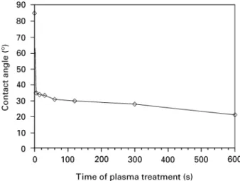
Figure 1 Water-contact angles, measured on polished PEEK sur-faces after plasma treatment. The contact angles were determined 1 min after contact between water drop and PEEK surface.
2.4. Thiazolylblue tetrazoliumbromide (MTT) assay
In the MTT assay the reduction of the water-soluble yellow MTT tetrazolium salt to the blue water-insoluble MTT-formazan by the mitochondrial enzyme succinic dehydrogenase was assessed. To each well of the 24-well plates 100ll of phosphate-buffered saline (PBS) containing 5 mg/ml MTT (Fluka Chemie AG, Switzerland) were added and the plates incubated for 2 h at 37 °C, 5% CO2. After incubation the cells were fixed for 5 min with Karnovski solution (4% parafor-maldehyde and 5% glutaraldehyde in PBS) and then rinsed twice with PBS. The MTT-formazan was ex-tracted by adding 1 ml of a solution consisting of 90% ethanol and 10% 50 mM 4-(2-hydroxyethyl)-piperazine-1-ethane sulphonic acid (HEPES)/NaCl (Fluka). One hundred microlitres of the solutions were transferred to microwell plates (Nunc) and the opticaldensity (OD) of the solution measured spectrometrically at 560 nm using a multiwell reader (Rainbow, SLT, Austria).
2.5. Neutral red (NR) assay
The neutral red assay is based on the accumulation of the red dye in the lysosomes of intact viable cells. The assay was performed by adding 200ll of 3.5 mM 3- amino-m-dimethylamino-2-methyl-phenazine-hydro-chloride (NR, Sigma) in PBS to each well of the 24-well plates. Incubation and fixation of the cells were performed as described for the MTT assay. The chromophore was solubilized by adding 1 ml iso-propanol containing 0.4% conc. HCl (v/v). Analog-ously to the MTT assay, the OD of the solution was measured at 540 nm.
2.6. BrdU-enzyme-linked immunosorbent assay (ELISA)
BrdU-ELISA test was performed with a 5-Bromo-2 @-deoxyuridine Labelling and Detection Kit III (Boehringer Mannheim Biochemica). BrdU-labelling was performed by adding 40ll of 5-bromo-2@-deoxy-uridine to each well. The plates were incubating for at least 5 h at 37 °C. After incubation, washing was per-formed with 800—1000ll PBS containing 10% FBS. The cells were then fixed with 800ll of fixation me-dium (70% ethanol, 0.5MHCl) at !20 °C for 30 min. Four hundred microlitres of nucleases were added to each well and the plates were incubated at 37 °C for 30 min. After the addition of 400ll anti-BrdU-POD (peroxidase) antibody to each well the plates were incubated at 37 °C for another 30 min. Washing with a special washing buffer (included in the Detection Kit III) was performed subsequently and 400ll peroxidase substrate ABTST (2,2@-Azino-bis(3-ethylbenzthiazoline-6-sulfonic acid)) were added to each well. The concen-tration of the coloured reaction product was analysed by measuring the OD at 405 nm, as described above.
3. Results and discussion
3.1. Plasma activation
Surface activation in the plasma resulted in a chemical change of the PEEK surface. The contact angle,
mea-sured 1 min after exposure to air, decreased from an initial value of 85° to 25° after 600 s of plasma treat-ment (Fig. 1). Influence of air exposure was investi-gated with samples that were activated for 10 min. The following dependence of contact angle on the expo-sure time to air was observed (Fig. 2): after 30 s the contact angle was measured to be 13° and increased within a few minutes to a value of 30 to 35°. The contact angle remained stable at 35° up to 4 h of exposure to air (Fig. 2). In accordance with our obser-vations, it was shown [15, 16] that the contact angle for plasma-treated PEEK surfaces reached a plateau at about 35—45° after exposure to air and then re-mained stable for several weeks. The initial rise in the contact angle with increasing exposure time to air can be considered as being due either to adsorbates or to polar low-molecular-weight fragments that were pro-duced during plasma activation which then rapidly reoriented away from the surface of the material [15, 17].
The XPS spectra are referenced to the binding energy of the aromatic C—H bond at 284.7 eV. In the survey XPS-spectrum of the untreated PEEK surface, the C1s peak was the most intense one. The integral intensity of the oxygen peak increased with activation time while the intensity of the C-peak remained nearly constant after 10 min of plasma treatment (Fig. 3a).
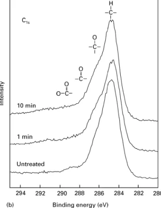
Figure 3 XPS survey: (a) C14; (b) and O14; (c) spectra of untreated and plasma-treated PEEK surfaces.
The shoulder at the high-binding energy side of the main, aromatic C14 peak was attributed to carbon atoms bonded with oxygen, i.e. C—O and C"O. After plasma treatment an augmentation of this shoulder was observed indicating an increase of the number of carbon atoms bound to oxygen (Fig. 3b). The detailed spectrum of the oxygen peak showed a strong increase of the O14 intensity (Fig. 3c). The form of the oxygen peak changed significantly after plasma treatment. After plasma activation the peak became more sym-metrical and the proportion of bonds contributing to the O14 intensity at higher binding energies, such as
phenolic, alcoholic, carboxylic and peroxy groups, increased. Based on these observations it is suggested that, in addition to the surface being cleansed of ad-ventitious hydrocarbon molecules, additional oxygen functionalities were produced on the PEEK surface because of plasma activation. This is in accordance with other investigations of the plasma treatment of PEEK [15, 16, 18]. Additionally, Pawson et al. [19] have observed the production of low-molecular-weight fragments such as phenols and more highly oxidized carbon functionalities after plasma oxidation of PEEK. In this study, uptake of nitrogen was not observed after plasma activation of PEEK; in fact, after 10 min plasma treatment all traces of the N14 peak (at 400 eV) had disappeared.
The C/O ratio of the untreated polymer has been calculated to be 4.80. From the stoichiometry of the PEEK repeat unit a C/O ratio of 6.33 was expected. Since organic materials undergo oxidative degrada-tion reacdegrada-tions in the presence of oxygen, numerous oxidation products can be formed. Heat, metal cata-lysts or irradation can assist these oxidation processes. In the manufacturing process of an end product, poly-mers can be subjected to one or more processing steps in the melt, i.e. injection moulding, extrusion or film moulding. In these processes the polymer melt is ex-posed to heat and mechanical shear forces which can lead to thermomechanical degradation due to chain scission and alkyl radical formation [20, 21]. Oxygen that is dissolved in the polymer reacts with the alkyl radicals forming peroxy radicals, ROO., leading to hydroperoxides and new alkyl radicals. Several prod-ucts have been identified after thermo-oxidative degra-dation of polymers, such as peracids, ketones, carbon
TA B LE I Calculated C/O ratio of untreated and plasma activated PEEK surfaces and correlation with measured water contact angle
Plasma activation C/O ratio Contact
time (min) angle (°)
0 4.80 85
1 3.04 31
10 2.86 21
Figure 4 Cell vitality on untreated and plasma-treated (10 min) PEEK surfaces (n"6). ( ) MTT; ( ) NR.
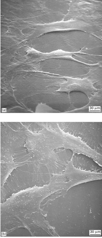
Figure 5 Scanning electron micrographs of osteoblast-like cells evenly spread on untreated (a) and plasma-treated (10 min) (b) PEEK surfaces.
acids and esters [22]. It is therefore suggested that the low C/O ratio of the untreated PEEK substrate, observed in this study, originates from the thermo-oxidative degradation during the injection moulding process. However, oxidative and thermo-mechanical degradation of PEEK under processing conditions is in need of further investigation. After 10 min of plasma activation, the C/O ratio decreased from an initial value of 4.80 to 2.86 (Table I), indicat-ing an increased oxidation of the PEEK surface. Cell viability testing with MTT and NR assays showed that there is no effect of plasma activation on cell viability (Fig. 4). Cells were evenly spread on both
untreated and plasma treated PEEK surfaces
(Fig. 5a, b).
3.2. Coating characterization
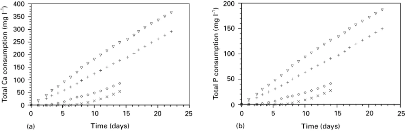
Coatings of a thickness of up to 50lm were obtained after 24 days by precipitation in the supersaturated calcium phosphate solution. The build-up of the coating was as follows: a nucleation layer was formed on the PEEK surface with a spherulite-like shape (Fig. 6a). On this layer, crystallites with a rosette-like shape crystallized and grew (Fig. 6b). EDX analysis of the precipitated coatings revealed the Ca and P to be the only components of the coating (Fig. 7). The deposition of Ca and P onto the PEEK substrates continued at a constant rate (Fig. 8a—d). ICP—AES analysis showed the influence of the nucleation pro-cess and the plasma treatment on the consumption of calcium, which can be directly correlated to the growth of the coating. Fig. 8a shows the influence of
nucleation and plasma activation on the growth rate of the calcium phosphate layer. Plasma activation slightly increased the consumption rate of Ca and P. However, significant increase of the consumption rate was noted at the nucleated substrates. Calcium phos-phate formation on non-nucleated surfaces was re-tarded. The incubation time of calcium and phosphate deposition could be shortened by plasma treatment (Fig. 8a, b).
R! (arithmetic mean deviation of the surface profile) values of sandblasted surfaces were measured to be 3.75$0.91lm, compared to the polished speci-mens with R!"0.05$0.03 lm. Surprisingly, surface
Figure 6 Scanning electron micrographs of nucleation layer on the PEEK surfaces with a thickness of about 10lm and a spherulite-like shape (a). On the nucleation layer, crystallites with a rosette-like morphology were formed (b).
Figure 7 Energy dispersive X-ray spectrum of the precipitated coat-ing on PEEK.
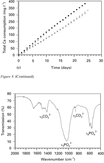
Figure 8 Influence of plasma activation and subsequent nucleation on the total Ca (a) and P (b) consumption for coating formation on polished surfaces. (£) 7 days nucleation, with plasma activation; (#) 7 days nucleation, no activation; (e) no nucleation, with plasma activation; (]) no nucleation, no activation. Influence of sandblasting and plasma activation on the total Ca (c) and P (d) consumption for coating formation on PEEK surfaces. The substrates were nucleated for 7 days prior to the coating process. (#) polished, no activation; (e) polished, with plasma activation; (]) sandblasted, no activation; (r) sandblasted, with plasma activation.
roughening through sandblasting and the consequent increase of the specific surface area had no significant effect on the deposition rate (Fig. 8c—d). The highest rate of calcium phosphate formation was achieved by a combination of plasma treatment and nucleation.
FTIR analysis revealed m3- and m4-PO4 bands at wavelengths of 1034 cm~1 and 603/565 cm~1, respec-tively (Fig. 9). Peaks appearing at 873 cm~1 and 1400—1460 cm~1 were assigned to m2-CO3 and m3-CO3 bands, respectively, indicating that the coating con-sists of a carbonate-containing calcium phosphate.
The in vitro formation of a carbonate apatite layer on different substrates, such as silica-gel and various polymers, has been reported in the literature [23, 24]. It has also been reported that the formation of a car-bonate-containing apatite layer on implant surfaces is
Figure 8 (Continued).
Figure 9 FTIR analysis of the precipitated coating on PEEK.
Figure 10 Cell vitality testing of coated PEEK surfaces compared with sandblasted PEEK reference and PS control (n"9).
necessary for bone bonding [25, 26]. In our study, preliminary cell viability testing showed an increase in succinic dehydrogenase activity of the osteoblastic cell line on the coated sample as compared to the reference material (Fig. 10). With NR-assay and BrdU-ELISA tests a similar trend was observed. Therefore, it is assumed that the biological performance of PEEK
with respect to bone bonding and the development of a bond implant interface will be positively influenced by the precipitated calcium phosphate coating.
4. Conclusions
Activation of PEEK with N2/O2 plasma led to a sig-nificant reduction of the contact angle, which can be correlated with an increase in the oxygen content at the surface. It therefore appears that additional oxy-gen functionalities have been formed on the PEEK surfaces by plasma treatment, although a sizeable frac-tion of these may have rapidly reoriented themselves away from the surface. The possibility of coating PEEK with calcium phosphate by precipitation was demonstrated in this study. Plasma treatment com-bined with a nucleation process showed the highest rate of coating formation during subsequent calcium phosphate precipitation. A carbonate-containing cal-cium phosphate layer with a thickness of up to 50lm was formed following 24 days of immersion in a cal-cium- and phosphate-saturated solution. Cell viability tests have shown that the newly formed functionalities after plasma treatment had no disadvantageous effect on cytocompatibility. Compared to the reference PEEK material, cell viability on the samples coated with calcium phosphate was significantly increased as measured by the MTT test. It is therefore expected that the calcium phosphate coating on the PEEK surface will influence the bone bonding properties and the development of the bone implant interface. Never-theless, more detailed in vitro studies and clinical rel-evance of the precipitated calcium phosphate coatings have to be further investigated.
References
1. A . S . V A U G H A NandS . J. SU T T ON, Polymer 36 (1995) 1549. 2. D. F . W I L L IA M S,A . Mc N A M A R A andR . M . T U R N E R,
J. Mater. Sci. ¸ett. 6 (1987) 188.
3. E . WI N T E R M A N T E LandJ . MA Y E R, in ‘‘Encyclopedia of biomaterials and bioengineering’’, Part B, Vol. 1, edited by D. L. Wise, D. J. Trantolo, D. E. Altobelli, M. J. Yaszemski, J. D. Gresser and E. R. Schwartz (M. Dekker Inc., New York, 1995) p. 3—42.
4. A . J . G OL D B E R G, C . J . B U R S T O N E, I . H A N D J I N I -KO L A O UandJ . J A N C A R, J. Biomed. Mater. Res. 28 (1994) 167.
5. K. B . K WA R T E N GandC . ST A R K, Sampe Quart. 22 (1990) 10. 6. M. W I D M E R, J . I SL E R, T . C A L L E N B A C H, M . F R O® H -L I C H, D . M E IE R, J . M A Y E R, E . WI N T E R M A N T E L, P . T S C H A N Z,H . L U®T H I,K . M A Z E N A U E RandL . K L O S -T E R M A N N, Oberfla¨chen ¼erkstoffe 5 (1995) 34. 7. K. A . J OC KI S C H, S . A . B R O WN, T . W . B A U E R and K. M E R R I T T, J. Biomed. Mater. Res. 26 (1992) 133. 8. T . T E R J E S E NandK . A P A L S E T, J. Orthop. Res. 6 (1988) 293. 9. C . A . E N G HandJ . D . B O B Y N, Clin. Orthop. Rel. Res. 231
(1988) 7.
10. H. O G U C H I,K . I S H I K A W A,K . M IZ O U E,K . SE T Oand G. E G U C H I, Biomaterials 16 (1995) 33.
11. G. T . G E E S I NK, Clin. Orthop. Rel. Res. 261 (1990) 39. 12. J . F . O SB O R N, in ‘‘Biomaterials degradation’’, edited by
M. A. Barbosa (Elsevier Science Publishers B.V., Amsterdam, 1991) p. 185.
13. S. - W . H A,J . MA Y E R,B . K O C H Iand E . WI N T E R M A N -T E L, J. Mater. Sci. Mater. Med. 5 (1994) 481.
14. S. E V A N S, R . G . P R I T C H A R D and J . M . T H O M A S, J. Electr. Spectrosc. Rel. Phenom. 14 (1978) 341.
15. W. J . B R E N N A N,W . J . F E A S T,H . S . M U N R OandS . A . WA L K E R, Polymer 32 (1991) 1527.
16. H. S . M U N R OandD . I . M C B R I A R, J. Coatings ¹echnol. 60 (1988) 41.
17. D. B R I G G S andM . P . S E A H, ‘‘Practical surface analysis’’ (John Wiley and Sons, Chichester, 1983) p. 359.
18. A . B A A L M A N N,K . D . V I S SI N G,E . B O R NandA . G R O S S, J. Adhesion 46 (1994) 57.
19. D. J. P A W S O N,A . P . A M E E N,R . D. S H O R T,P . D E N I S O N andF . R . J O NE S, Surf. Interf. Anal. 18 (1992) 13.
20. H. H I N S K E N,S . M O S S,J . R . P A U Q U E TandH . Z WE I F E L, Polym. Degrad. Stabil. 34 (1991) 279.
21. W . O . D R A K E, J . R . P A U Q U E T, R . V . T O D E SC O and H. Z W E I F E L, Angew. Makromolek. Chemie 176/177 (1990) 215.
22. P . G I J S M A NandJ . H E N N E K E N S, Polym. Degrad. Stabil. 42 (1993) 95.
23. P . L I, C . O H T S U K I, T . K O K UB O, K . N A K A N IS H I, N. SO G A,T . N A K A M U R AandT . Y A M A M U R O, J. Mater. Sci. Mater. Med. 4 (1993) 127.
24. T . K O K U B O,M . T A N A H A S H I,T . Y A O,M . M I N O D A,T . MI Y A M O T O, T . N A K A M U R Aand T . Y A M A M U R O, in ‘‘Bioceramics 6’’, edited by P. Ducheyne and D. Christiansen (Butterworth-Heinemann, Ltd, Philadelphia, 1993) p. 327. 25. G. D A C U L S I,R . Z . L E G E R O S,M . H E U G H E B A E R Tand
I. B A R B I E U X, Calcified ¹issue Int. 46 (1990) 20.
26. P . D U C H E Y N E,S . R A D INandL . K I N G, J. Biomed. Mater. Res. 27 (1993) 25.
Received 11 July 1996
and accepted 13 February 1997