An Airbag-Based Crew Impact Attenuation System
for the Orion Crew Exploration Vehicle
by
Sydney Do
Bachelor of Engineering in Aeronautical (Space) Engineering
(Honours Class 1 & University Medal) (2008)
University of Sydney
Submitted to the Department of Aeronautics and Astronautics
in partial fulfillment of the requirements for the degree of
Master of Science in Aeronautics and Astronautics
at the
MASSACHUSETTS INSTITUTE OF TECHNOLOGY
February 2011
© Massachusetts Institute of Technology 2011. All rights reserved.
Author………
Department of Aeronautics and Astronautics
January 27, 2011
Certified by………
Olivier L. de Weck
Associate Professor of Aeronautics and Astronautics
Associate Professor of Engineering Systems
Thesis Supervisor
Accepted by………...
Eytan H. Modiano
Associate Professor of Aeronautics and Astronautics
Chair, Committee on Graduate Students
An Airbag-Based Crew Impact Attenuation System
for the Orion Crew Exploration Vehicle
by
Sydney Do
Submitted to the Department of Aeronautics and Astronautics
on January 27, 2011 in partial fulfillment of the requirements for the degree of Master of Science in Aeronautics and Astronautics
Abstract
It is a well known fact that every capsule-shaped reentry vehicle developed by NASA was initially conceived to land on land, but was ultimately designed to land in water. In all cases, the primary factor contributing to this fundamental shift was related to difficulties with keeping the vehicle to within its mass allocation. In recognizing the recurrence of this scenario during the development of the Orion Crew Exploration Vehicle (CEV), the concept of airbag-based crew impact attenuation was identified as being a potential means for providing a low mass, reconfigurable alternative to the currently baselined pallet-strut design. This thesis presents the development effort undertaken to determine the feasibility of this concept in terms of protecting an astronaut from the impact loads incurred during the nominal 7.62m/s Orion CEV landing on land.
Through the complete development and testing of an analog airbag system and an intermediate technology demonstrator, practical means for system implementation have been developed, and insights into the influence of the system configuration on its overall impact attenuation performance obtained. These findings have culminated in the design and implementation of a full-scale multi airbag system, which has been experimentally shown to be capable of maintaining the risk of injury to the occupant during a 7.85m/s, 0° impact angle land-landing to within the NASA specified limit of 0.5%. In accomplishing this, the airbag-based impact attenuation concept has been proven to be feasible.
Moreover, the obtained test results suggest that by implementing anti-bottoming airbags to prevent direct contact between the system and the landing surface, the system performance during landings with 0° impact angles can be further improved, by at least a factor of two. Additionally, a series of drop tests from the nominal Orion impact angle of 30° indicated that severe injury risk levels would be sustained beyond impact velocities of 5m/s. This is due to the differential stroking of the airbags within the system causing a shearing effect between the occupant seat structure and the spacecraft floor, removing significant stroke from the airbags.
These results combined indicate that with further detailed design in the context of the currently fixed Orion crew cabin design, and the enforcement of a flat impact angle during landing, airbag-based impact attenuation may prove to be the key to finally achieving the elusive goal of capsule-shaped vehicle reentry and land-landing.
Thesis Supervisor: Olivier L. de Weck
Financial support for this research was provided by the NASA Engineering and Safety Center (NESC) and the Constellation University Institutes Project (CUIP) under prime award number NCC3989 and subaward number Z634013
Acknowledgments
This work represents the journey in which I have taken over the past two and a half years of my life, where I have been fortunate enough to learn from the best of the best, and been given the opportunity to make a direct contribution to my lifelong passion of human spaceflight. Through this, I have grown both as an engineer, and as a person – both of which could not have been possible without the support of dozens of people; all of whom I would like to extend my sincerest gratitude. Although there are too many to mention by name, I would like to make a special mention of a few of the people who have so positively impacted my MIT experience. In particular, I would like to thank…
Professor Olivier “Oli” de Weck for agreeing to meet with me on that fateful day in early October 2008, when a starving grad student entered his office with thoughts of “will research for food” running through his mind. Not only did Oli provide me with the opportunity to work on an amazing project, he has also exposed me to a world in which not so long ago, I believed was out of reach. Never in my wildest dreams as a kid growing up in the southwestern suburbs of Sydney did I think that one day I’d be able to experience the exhilaration of zero gravity, or be awestruck by seeing first hand, the amazing things that occur at NASA’s research and spaceflight centers. His guidance and support throughout this adventure has been invaluable, and for this, I am eternally grateful.
Todd Billings, Dave Robertson, and Dick Perdichizzi for their important advice and assistance in all design, construction, data acquisition, and testing performed as part of this project. Without their support (and the numerous free parts and raw materials supplied by them), this project would never have been possible to undertake, let alone complete within our cost constraints.
The numerous undergraduate students from both MIT and PSU who came onboard the project throughout its evolution: Peter Cheung, Alban Cobi, Adrian Dobson, Josh Gafford, Daniel Goodman, Ricardo Robles Jr., Jackson Siu, Jared Trotter, and Jack Weinstein. Even though there were times when it looked like we weren’t going to be able to solve a particular problem or meet a deadline, their hard work, dedication, and creativity kept the project moving along.
Joe Pellicciotti, Tim Brady, Charlie Camarda, Chuck Lawrence, Lisa Jones, Cory Powell, Ed Fasanella, and the other members of the NESC team who provided valuable technical support and equipment for this project.
The many people who have helped make my grad school experience a memorable one. In particular, I would like to thank the “Mates” – Jon Allison, Hemant Chaurasia, Pritesh Mody, Hiten Mulchandani, and Russ Stratton; as well as Indira Deonandan and Howard Yue for their friendship and for providing me with a forum where I could speak Australian slang and be at least partially understood. Additionally, I’d like to thank my Hawaiian peeps – Vivian Diep, Bo Hong, and Riho Hayashi for all the laughs; as well as Angel An for her support and entertainment.
My friends who helped with system fabrication, testing and the proofreading of this thesis: Vishnu Desaraju, Justin Kaderka, Sung Wook Paek and the aforementioned Mr Chaurasia, Mr Mody, and Miss Diep.
The members of the Boston center of the Supreme Master Ching Hai International Association for their support; and for providing me with food which literally kept me alive for the first few months of my stay in Boston.
And finally, to my mother, for her love, and all the sacrifices that she has made for me to pursue my dreams.
Contents
1. Introduction ... 25
1.1 Background and Motivation ... 25
1.2 Objective and Approach ... 30
1.3 Thesis Outline ... 32
2. Literature Review ... 35
2.1 Terrestrial Airbag Systems ... 35
2.1.1 Garment-Based Airbag Systems ... 35
2.1.2 Seat-Based Airbag Systems ... 39
2.1.3 Cabin-Based Airbag Systems ... 42
2.1.4 Summary of Relevant Terrestrial Airbag System Concepts ... 45
2.2 Spacecraft Airbag Systems ... 47
2.2.1 Project Mercury ... 47
2.2.2 Luna 9 and 13 ... 48
2.2.3 Mars Pathfinder and Mars Exploration Rover ... 49
2.2.4 Orion Crew Exploration Vehicle ... 51
2.2.5 ExoMars... 52
2.2.6 Summary of Relevant Spacecraft Airbag System Concepts... 53
2.3 Human Spaceflight Impact Attenuation Systems ... 54
2.3.1 Vostok ... 54
2.3.2 Project Mercury ... 56
2.3.3 Voskhod and Soyuz ... 57
2.3.5 Apollo ... 60
2.3.6 Summary of Relevant Features of Past Human Spacecraft Impact Attenuation Systems ... 62
2.4 Chapter Summary ... 64
3. The Impact Attenuation Problem ... 67
3.1 Airbag Impact Dynamics Modeling ... 67
3.1.1 Thermodynamic Analysis ... 68
3.1.2 The Single Airbag Impact Model Framework ... 75
3.1.3 The Integrated Single Airbag Impact Model ... 85
3.2 Human Injury-Risk Modeling ... 90
3.2.1 The Brinkley Direct Response Index ... 90
3.2.2 Injury-Risk Mitigation ... 93
3.3 Photogrammetric Methods for Impact Analysis ... 96
3.4 Chapter Summary ... 99
4. Analog-Airbag System Development ... 101
4.1 Analog-Airbag System Design ... 101
4.1.1 System Configuration ... 102
4.1.2 Airbag Sizing ... 103
4.1.3 Test Hardware and Infrastructure Design ... 106
4.1.4 Airbags to Beanbags ... 109
4.1.5 Analog-Airbag System Manufacture ... 110
4.2 Analog-Airbag System Drop Test Plan ... 113
4.3 Analog-Airbag System Test Results & Analysis ... 114
4.3.1 Considerations Regarding Measurement Uncertainty ... 117
4.3.2 Typical Results ... 118
4.3.3 Trends with Varying Drop Height ... 123
4.3.4 Summary of Analog-Airbag Test Campaign Findings ... 127
4.4 Chapter Summary ... 128
5. Single Airbag Impact Dynamics Investigation ... 129
5.1.1 System Configuration ... 130
5.1.2 Design of Experiments ... 133
5.1.3 Valve Development ... 139
5.1.4 Airbag Material Testing and Leakproofing ... 150
5.1.5 Pressure Relief Valve Vented Airbag Optimization ... 157
5.1.6 Single Airbag Drop Test Article Manufacture ... 161
5.2 Single Airbag System Drop Test Plan ... 163
5.3 Single Airbag System Test Results & Analysis ... 165
5.3.1 Test Session 1 Results Analysis ... 166
5.3.2 Test Session 2 Results Analysis ... 168
5.4 Single Airbag Impact Model Refinement ... 174
5.5 Design Space Exploration ... 181
5.5.1 Single Objective Optimization ... 182
5.5.2 Multi-Objective Optimization ... 194
5.6 Chapter Summary ... 196
6. Multi-Airbag System Development ... 197
6.1 Multi-Airbag System Modeling ... 197
6.2 Multi-Airbag System Development ... 204
6.2.1 Airbag Configuration Design and Sizing ... 204
6.2.2 Seat Support System Development ... 218
6.2.3 Generation 3.1 Flapper Valve ... 220
6.2.4 Airbag Manufacture ... 222
6.2.5 Multi-Airbag System Integration ... 224
6.3 Multi-Airbag System Drop Test Plan ... 226
6.4 Multi-Airbag System Test Results & Analysis ... 229
6.4.1 Pressure Relief Valve Performance ... 231
6.4.2 Test Session 1 Results Analysis ... 233
6.4.3 Test Session 2 Results Analysis ... 241
6.5 Chapter Summary ... 248
7. Conclusions ... 251
7.1.1 Findings from Preliminary Modeling of the Airbag-Based Impact
Attenuation Problem ... 252
7.1.2 Findings from the Development of the Analog-Airbag System ... 252
7.1.3 Findings from the Single Airbag Impact Dynamics Investigation ... 253
7.1.4 Findings from the Development of the Multi-Airbag System ... 253
7.2 Recommendations for Future Work ... 254
Appendix A. Project Team Members ... 257
Appendix B. Model Newton Iteration Function Derivation ... 259
Appendix C. Mass Comparison between Crew Impact Attenuation Systems ... 263
List of Figures
1-1 The Orion Crew Exploration Vehicle ... 26
1-2 Comparison of Impact Attenuation Systems ... 28
1-3 Original Sketches from NESC Academy Design Course ... 29
1-4 Initial System Concept of Operations ... 30
1-5 Three Level Spiral Model used for this Development Effort ... 31
2-1 Xenith X1TM Football Helmet ... 36
2-2 Marco Simonelli falls off his motorcycle during the 2007 Valencia Grand Prix ... 37
2-3 Mugen Denko Hit-Air Shock Buffering System ... 37
2-4 The Itsumo Safety Life Jacket ... 38
2-5 Suit-Based Airbag Systems marketed by the NIIS and Prop Company ... 39
2-6 Inflatable Seat Concept ... 40
2-7 Inflatable Seat Cushions ... 40
2-8 Amsafe Commerical Aviation Seatbelt Airbag ... 41
2-9 Inflatabelt Concepts developed by BAE Systems ... 42
2-10 Airbag system in a 2007 Model Honda Accord ... 43
2-11 Airbag Applications in Terrestrial Vehicles ... 43
2-12 F-111 Crew Escape Module Airbags ... 44
2-13 Helicopter Out-of-Cabin Airbag Systems... 45
2-14 Mercury Landing Airbag System ... 48
2-15 Luna 9 and 13 Landing Sequence ... 49
2-16 Mars Pathfinder Mission ... 50
2-17 Mars Exploration Rover Mission ... 50
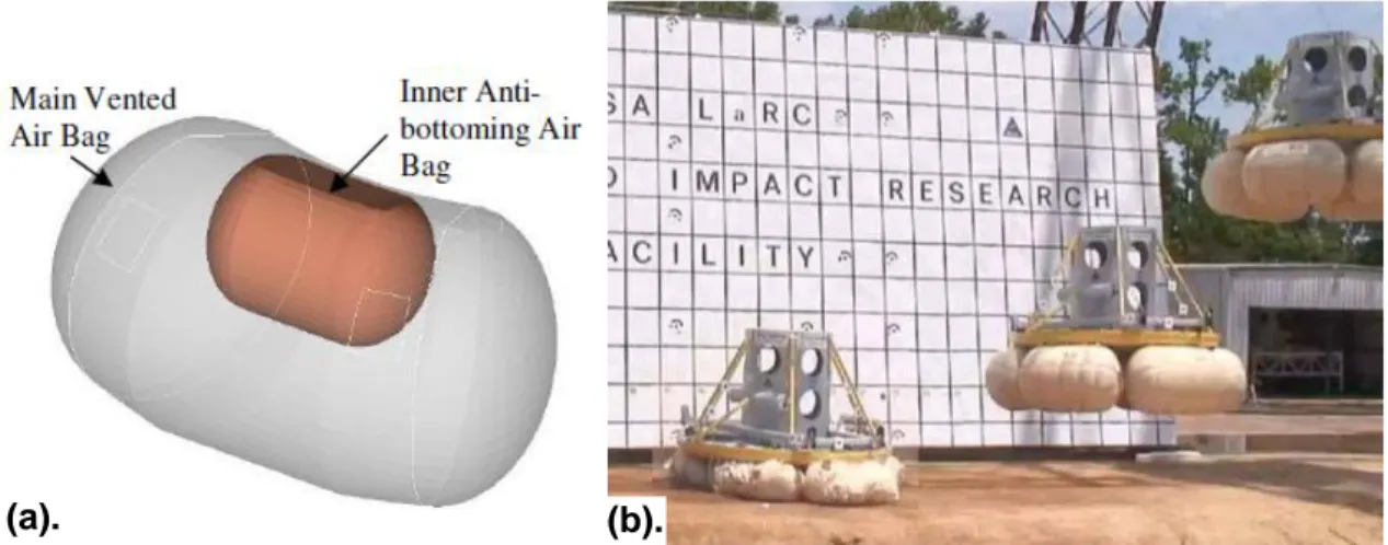
2-19 Orion External Airbag System ... 52
2-20 ExoMars Landing Sequence ... 53
2-21 Drop testing of a prototype of the ExoMars airbag system ... 53
2-22 Vostok Mission ... 55
2-23 A technician works on the Mercury couch ... 56
2-24 Soviet Shock Absorbing Seats ... 57
2-25 Gemini Descent and Landing ... 59
2-26 Ejection Seats used in the Gemini spacecraft ... 59
2-27 Apollo Couch Impact Attenuation System Configuration ... 60
2-28 Detail of Apollo Crew Couch ... 61
3-1 Initial Condition for Thermodynamic Analysis ... 68
3-2 System State Transition ... 71
3-3 System during the Venting Phase ... 73
3-4 Overview of Developed Single Airbag Impact Model ... 75
3-5 Single Airbag Impact Model Initial Condition ... 76
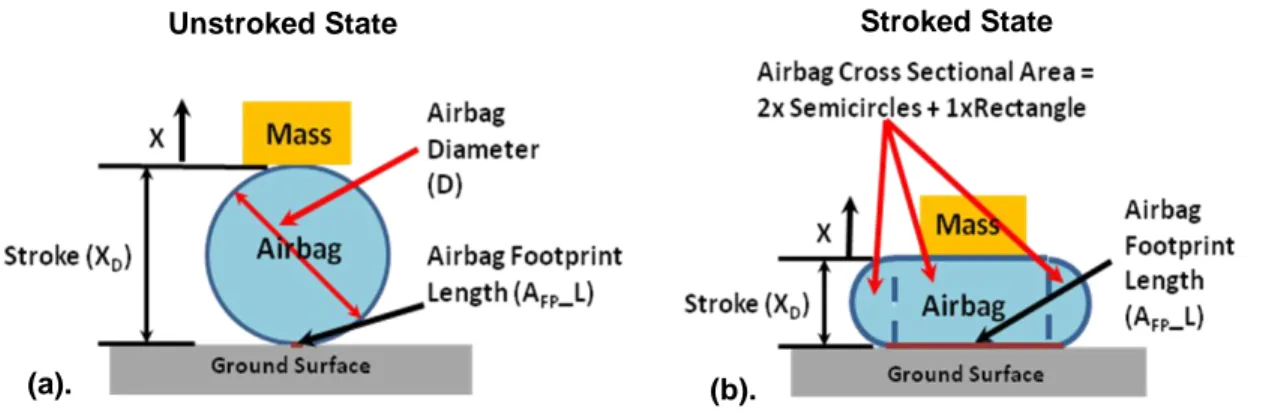
3-6 Shape Function used in Single Airbag Impact Model ... 77
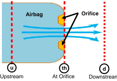
3-7 Upstream and Downstream Pressure as used by the Single Airbag Impact Model ... 81
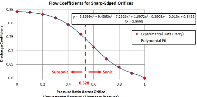
3-8 Data used to Model the Discharge Coefficient ... 85
3-9 Single Airbag Impact Model Functional Flow Block Diagram ... 86
3-10 Brinkley Reference Frame ... 91
3-11 Magnification Effects of the Dynamic Amplification Function ... 95
3-12 Dot Detection Algorithm Functional Flow Block Diagram ... 97
3-13 Line Detection Algorithm Functional Flow Block Diagram ... 98
3-14 Summary of Photogrammetric Analysis Process ... 99
4-1 Baseline Airbag Configuration ... 102
4-2 Predicted Performance for the First Generation Personal Airbag System ... 106
4-3 Test Article and Infrastructure Design Features ... 107
4-4 Detail of Seat Frame Design ... 107
4-5 Drop Test Infrastructure... 108
4-6 Anthropomorphic Test Device used during all Drop Test Campaigns ... 109
4-7 High Strength Polyester Tensile Strength Testing ... 111
4-8 Exploded View of Beanbag Fill Valve Design ... 112
4-10 Integrated First Generation System ... 113
4-11 First Generation System Test Setup... 114
4-12 Typical Dynamic Response Seen During Testing ... 115
4-13 Test Failure from a 5 foot Drop Height ... 116
4-14 Photogrammetrically Obtained Test Results for a 3 foot Drop ... 119
4-15 Dynamic Breakdown of Accelerometer Data obtained from a 3 foot Drop Test ... 120
4-16 Resimulated System Dynamics for a 3 foot Test Drop ... 121
4-17 Injury-Risk Responses for a 3 foot Test Drop ... 122
4-18 X-Direction Acceleration for all Generation 1 System Drop Tests ... 124
4-19 X-Direction Brinkley Index for all Generation 1 System Drop Tests ... 125
4-20 Low Injury-Risk β-Number for all Generation 1 System Drop Tests ... 125
4-21 Impact Velocity for all Generation 1 System Drop Tests ... 126
5-1 Generation 2 Personal Airbag System Configuration ... 130
5-2 Generation 2 Individual Airbag Configuration ... 131
5-3 Tilting of the First Generation System after a 3ft Drop ... 132
5-4 Brinkley Response with fixed x0 and Varying Inflation Pressure ... 134
5-5 Brinkley Response with fixed x0 and Varying Orifice Diameter ... 135
5-6 Brinkley Response with fixed x0 and Burst Acceleration ... 135
5-7 Brinkley Response with fixed x1 and Varying Inflation Pressure ... 136
5-8 Brinkley Response with fixed x1 and Burst Acceleration ... 137
5-9 Brinkley Response with fixed x* and Varying Orifice Diameter ... 138
5-10 Comparison between ValveTech flapper valve and valve developed in-house ... 142
5-11 Flapper Valve Leakage Testing Setup ... 143
5-12 Close up views of leakage of First Generation Flapper Valve ... 143
5-13 Second Generation Flapper Valve ... 146
5-14 Third Generation Flapper Valve ... 147
5-15 Third Generation Flapper Valve Characterization Test Setup ... 148
5-16 Third Generation Flapper Valve Characterization Testing Results ... 148
5-17 Idealized Valve Torsional Spring Model ... 149
5-18 Flapper Valve Mounting Concept... 150
5-19 Vectran Tensile Test Samples... 152
5-20 Vectran Tensile Strength Test Resultsc ... 153
5-22 Liquid Latex Coating Test Setup ... 155
5-23 Leakage Test Result ... 156
5-24 Silicone Paint Applied to Fabric Seam ... 156
5-25 Pressure Relief Valve Vented Airbag Design Space ... 158
5-26 Predicted Brinkley Response for the Single Airbag Test Article ... 159
5-27 Predicted Vertical Displacement Response for the Single Airbag Test Article ... 160
5-28 Final Integrated Single Airbag Drop Test Article Design ... 161
5-29 Single Airbag Drop Test Article ... 162
5-30 Single Airbag Drop Test Article ... 163
5-31 Single Airbag Drop Test Setup ... 164
5-32 Typical Dynamic Observed During all Single Airbag System Drop Tests ... 165
5-33 Single Airbag Drop Test Article Failure at 6 foot Drop Height ... 166
5-34 Single Airbag Drop Test Session 1 Accelerometer Data ... 167
5-35 Single Airbag Drop Test Session 1 Pressure Transducer Data ... 167
5-36 Single Airbag Drop Test Session 1 Pressure Transducer Data ... 168
5-37 Photogrammetric Analysis of High Speed Camera 1 Footage ... 169
5-38 Dynamics Data Extracted from Photogrammetry ... 169
5-39 Accelerometer Data for a 4foot Drop ... 170
5-40 Pressure Transducer Data for a 4foot Drop ... 171
5-41 X-Direction Acceleration for all Single Airbag System Drop Tests ... 172
5-42 X-Direction Brinkley Index for all Single Airbag System Drop Tests ... 173
5-43 Airbag Pressure for all Single Airbag System Drop Tests ... 173
5-44 Comparison between Original Predictions and Experimental Data for a 4 foot Drop175 5-45 Comparison between Refined Predictions and Experimental Data for a 4 foot Drop 176 5-46 Acceleration Response over Varying Payload Mass ... 177
5-47 Brinkley DRI Response over Varying Payload Mass ... 178
5-48 Acceleration Response over Varying Impact Velocity ... 179
5-49 Brinkley DRI Response over Varying Impact Velocity ... 180
5-50 Unscaled SQP Iteration History and Solution ... 186
5-51 Scaled SQP Iteration History and Solution... 188
5-52 Simulated Annealing Iteration History and Solution ... 190
5-53 Comparison of Orifice Opening Area under Different Airbag Geometries ... 191
5-55 Full Factorial Expansion of the Objective Space ... 195
6-1 Baseline Two Degree of Freedom Multi-Airbag Model ... 198
6-2 Multi-Airbag Impact Model Functional Flow Block Diagram ... 203
6-3 Baseline Airbag Configuration for the Multi-Airbag System Design Iteration 1 ... 206
6-4 High Resolution Full Factorial Expansion for the first Multi-Airbag Iteration ... 208
6-5 Baseline Airbag Configuration for the Multi-Airbag System Design Iteration 2 ... 209
6-6 High Resolution Full Factorial Expansion for the Second Multi-Airbag Iteration .... 211
6-7 Second Multi-Airbag System Iteration Objective Space Filtered by Airbag Length . 212 6-8 Baseline Airbag Configuration for the Multi-Airbag System Design Iteration 3 ... 213
6-9 High Resolution Full Factorial Expansion for the Third Multi-Airbag Iteration ... 213
6-10 Third Multi-Airbag System Iteration Objective Space Filtered by Airbag Length .... 214
6-11 Objective Space Filtered by Max Hoop Stress < 540MPa & L = 0.26m or 0.28m .... 215
6-12 Predicted Brinkley DRI for the Nominal 30° Impact Case ... 216
6-13 Predicted System Dynamic for the Nominal 30° Impact Case ... 217
6-14 Predicted Brinkley DRI for the Nominal 0° Impact Case ... 217
6-15 Predicted System Dynamic for the Nominal 0° Impact Case ... 217
6-16 Overarching Multi-Airbag System Concept ... 218
6-17 Original Seat Support System Sketches ... 219
6-18 Seat Support System Sizing ... 219
6-19 Final Manufactured Seat Support Structure ... 220
6-20 Generation 3.1 Pressure Relief Valve Design ... 220
6-21 Generation 3.1 Pressure Relief Valve Leakage Test Setup ... 221
6-22 Manufactured Generation 3.1 Pressure Relief Valve Components ... 222
6-23 Airbag Seam Layering Scheme ... 222
6-24 Airbag Crush-Up Test ... 223
6-25 Integrated Airbag ... 224
6-26 System Hoist Test ... 224
6-27 Center of Gravity Testing ... 225
6-28 Fully Integrated Second Generation Personal Airbag System ... 226
6-29 Drop Test Configuration ... 227
6-30 Multi-Airbag System Drop Test Setup ... 228
6-31 Multi-Airbag System Drop Test Campaign Camera Locations and Views ... 229
6-33 Frame by Frame Breakdown of the 7 foot, 30° Impact Angle Drop ... 230
6-34 Breakdown of the Pressure Relief Valve Performance ... 231
6-35 Pressure Transducer Output for all Test Session 1 Drop Tests ... 232
6-36 Pressure Transducer Output for all Test Session 2 Drop Tests ... 232
6-37 Test Session 1 X-Direction Acceleration Results ... 233
6-38 Test Session 1 X-Direction Brinkley DRI Results ... 234
6-39 Test Session 1 Low Injury-Risk β-Number Results ... 234
6-40 Test 19 Acceleration Response with Anomalous Consecutive Peaks Highlighted .... 236
6-41 Summary of Data Time Synchronization Process ... 237
6-42 Session 1 Test 19 Normalized and Time Synchronized Data Set ... 238
6-43 Session 1 Test 19 - Dynamically Tagged X-Direction Acceleration Response ... 239
6-44 Effects of Drop Height on Bottoming-Out of Multi-Airbag System ... 240
6-45 Potential System Dynamics without Bottoming-Out ... 241
6-46 Test Session 1 X-Direction Acceleration Results ... 242
6-47 Test Session 2 X-Direction Brinkley DRI Results ... 242
6-48 Test Session 2 Low Injury-Risk β-Number Results ... 243
6-49 Session 2 Test 13 Normalized and Time Synchronized Data Set ... 244
6-50 Breakdown of Valve Performance and Obstruction during Session 2 –Test 13... 245
6-51 Session 2 Test 13 - Dynamically Tagged X-Direction Acceleration Response ... 246
List of Tables
2.1 Summary of Reviewed Airbag System Concepts ... 65
3.1 Values Assumed for the Thermodynamic Analysis ... 69
3.2 NASA HSIR specified natural frequencies and damping ratios ... 92
3.3 NASA HSIR Specified Brinkley DRI Limits ... 92
3.4 Brinkley Limits for Moderate and High Risks of Injury ... 93
4.1 Parameter Values Forming the Optimization Space for Each Airbag ... 104
4.2 Airbag Parameter Values for First Generation CIAS Design ... 105
4.3 Time Breakdown of Significant Dynamic Events for a 3ft Drop Test ... 120
4.4 Summary of Photogrammetric Analysis Results for all Drop Tests Performed ... 124
5.1 Baseline Design Vector for a Single Airbag with Burst Valves ... 139
5.2 Venting Mechanism Concepts Presented to the NESC ... 140
5.3 Pressure Relief Valves Offered by McMaster-Carr® ... 141
5.4 Summary of Leakage Tests Conducted during the Sealing Material Investigation.... 144
5.5 Summary of Leakage Tests Conducted during the Sealing Material Investigation.... 145
5.6 Vectran Tensile Strength Testing Results ... 153
5.7 Liquid Latex Coating Test Matrix ... 155
5.8 Final Design Vector for the Single Airbag Drop Test Article ... 159
5.9 Summary of Sensor and Photogrammetric Analysis Results ... 172
5.10 Factors and Levels for the Design of Experiments ... 183
5.11 Orthogonal Array Analysis Results ... 184
5.12 Main Effect of Design Variables determined from Orthogonal Array Analysis ... 184
5.13 Simulated Annealing Tuning Parameters ... 190
6.1 Factors & Levels used for the first iteration of the Multi-Airbag System Design ... 207
6.2 Maximum Hoop Stress Predictions (in MPa) for Design Iteration 1... 207
6.3 Variable Ranges used in the Multi-Airbag System Design Iteration 1 ... 208
6.4 Factors & Levels used for the second iteration of the Multi-Airbag System Design. 210 6.5 Maximum Hoop Stress Predictions (in MPa) for Design Iteration 2... 210
6.6 Final Second Generation Personal Airbag System Configuration ... 216
6.7 Multi-Airbag System Mass Properties ... 225
6.8 Summary of Multi-Airbag System Drop Test Session 1 Results ... 235
Nomenclature
Abbreviations
ASME American Society of Mechanical Engineers
ATD Anthropomorphic Test Device
BFGS Broyden Fletcher Goldfarb Shanno Method of approximating the Hessian
CEV Crew Exploration Vehicle
CG Center of Gravity
CIAS Crew Impact Attenuation System
CM Crew Module
CUIP Constellation University Institutes Project
CxP Constellation Program
DAQ Data Acquisition Unit
DOF Degree of Freedom
DR Direct Response
DRI Direct Response Index
GPS Global Positioning System
HSIR Human-System Integration Requirements ISS International Space Station
LaRC Langley Research Center
LED Light Emitting Diode
LLO Low Lunar Orbit
MIT Massachusetts Institute of Technology
NASA National Aeronautics and Space Administration NESC NASA Engineering and Safety Center
NPT National Pipe Thread
PSU Pennsylvania State University
SA Simulated Annealing
SQP Sequential Quadratic Programming
Roman Symbols
a Acceleration (Earth G’s)
a* Speed of Sound (m/s)
A Area (m2); Dynamic Amplification Function; Orifice Area (m2)
B Approximation to the Hessian
CD Discharge Coefficient CV Control Volume dk Search Direction D Airbag Diameter (m) E Energy Content (kJ) F Force (N)
g Gravitational Acceleration (m/s2); Inequality Constraints
h Height (m); Specific Enthalpy (kJ/kg); Equality Constraints
H Transfer Function
J Objective Function; Moment of Inertia (kg.m2)
k Spring Stiffness (N/m)
ke Specific Kinetic Energy (kJ/kg)
K Kinetic Energy (kJ)
KE Kinetic Energy (kJ)
L Length (m); Lagrangean Function
m Mass (kg); Main Effect
M Mach Number
N Number of Airbags
p Load (N)
p
~ Amplitude
P Pressure (kPa); Probability
q Generalized Coordinate
R Specific Gas Constant (J/kg/K); Spring Arm Length (m); Airbag Radius (m)
t Time Coordinate (s); Thickness (mm)
T Temperature (K); Torque (Nm)
u Vertical Degree of Freedom
U Internal Energy (kJ); Velocity (m/s)
v Random Number
V Volume (m3); Elastic Potential Energy (kJ)
V
Velocity (m/s)w Mass of Gas within Airbag (kg)
W Work (kJ)
x Vertical Displacement Coordinate (m)
X General Spatial Coordinate (m)
XD Airbag Stroke (m)
Greek Symbols
α Search Direction
β Beta Number
γ Ratio of Specific Heats
θ Spring Preload Angle (deg); Pitch Angle Degree of Freedom (deg)
Λ Length of Payload Mass (m)
ξ Damping Ratio ρ Density (kg/m3) σ Stress (Pa) ω Frequency (rad/s)
Subscripts
atm Atmospheric B Boundary bag Airbag burst Burstd Downstream
DIFF Differential
FP Footprint
GAS Airbag Gas
i Iteration Number
I Initial
IN Into System
Load Equivalent Load of Seat Structure
MASS Payload Mass
n Natural
N Normal
OUT Out of System
seam Seam SYS System t Time Increment T Torsion th Orifice u Upstream
x Spatial coordinate in the x-direction
y Spatial coordinate in the y-direction
z Spatial coordinate in the z-direction
Superscripts
Chapter 1
Introduction
Since the start of its development in late 2006, the Orion Crew Exploration Vehicle has experienced several modifications to its operational and design architecture as trade studies have been completed and more knowledge about the system obtained. One prevalent aspect which has been continually revisited throughout the program is the baseline mode in which the vehicle is to land on the Earth’s surface, and consequently the system concept which should be employed to facilitate this landing. This uncertainty has been linked to a combination of a strained mass budget, and difficulties in developing systems capable of protecting astronauts during all possible landing scenarios [1]. This thesis aims to provide further insight into this problem by evaluating the feasibility of implementing an alternative, lightweight, airbag-based impact attenuation system within the cabin of the Orion Crew Module. This work forms one component of a greater study conducted by the NASA Engineering and Safety Center (NESC) team tasked by the Constellation Program (CxP) Office to provide design recommendations for the Orion landing system architecture. Specifically, the results of this work will be used by the NESC to decide whether or not to further pursue the airbag-based impact attenuation system concept.
1.1
Background and Motivation
In early 2004, following the Space Shuttle Columbia accident, President George W. Bush announced the “Vision for Space Exploration” – a United States space policy aimed at returning humans to the Moon by the year 2020 in order to develop the skills, technology, and infrastructure required for sustained human exploration of Mars and other destinations in
the Solar System [2]. Emerging from this was the Constellation Program, a program within NASA aimed at developing and operating the hardware required to realize the Vision.
The first vehicle to be developed under this newly implemented program was the Orion Crew Exploration Vehicle (CEV), an all purpose human transportation system intended to operate to and from the International Space Station (ISS), Low Lunar Orbit (LLO), and eventually Martian orbit. One of the most revisited decisions in the development of this vehicle and its mission architecture was the mode in which it landed on the Earth’s surface at the completion of its mission.
Figure 1-1: The Orion Crew Exploration Vehicle [3]
It is an interesting fact that every capsule-shaped reentry vehicle developed by NASA initially had a specific requirement to land on land. Following detailed study, and accounting for the technical and schedule risks involved, it was deemed in every case that landing on water would be less demanding. With the schedule pressures of the Cold War space race long gone and the desire to develop a sustainable, long-term space transportation program; there was an interest in revisiting the possibility of developing a land-landing capability for Orion from the outset [4, 5]. Consequently, the CxP Office commissioned the NASA Engineering and Safety Center to assess the risks and costs involved in land versus water landings for Orion [4].
In this NESC study, the key advantages of land-landings were found to be related to the recovery and refurbishment of the vehicle. Recovering a vehicle from the sea is inherently more challenging than recovering one from land. This is due to the added difficulty in gaining access to a target moving in a dynamic marine environment, as well as the need to keep the vehicle afloat to prevent it from flooding [4]. These factors combine to add a time sensitivity to water recovery operations, which can be exacerbated in the scenario where a crew member is immobile due to injury or the effects of long-term spaceflight. Contrastingly, land-landings facilitate easier egress and recovery of the vehicle, while also mitigating the risk of it sustaining water damage. This latter attribute has implications on the ease of refurbishment of the spacecraft, which in turn impacts on the life-cycle costs of the program [1]. The disadvantage of employing a land-landing mode, however, is that the increased hardness of the landing surface results in higher accelerations being imparted upon the crew during impact. This hence requires a more complex, and inevitably higher mass system required to attenuate this additional load.
It was of the NESC’s view that the operational and life-cycle benefits of nominal land-landings far offset this additional complexity. This was supported by simulations which indicated that the inclusion of retro-rockets could easily maintain land-landing loads to within safe injury-risk levels, and that there was no major difference in development and post-landing recovery costs between each option [4]. Hence, based on this, the NESC recommended that the Orion CEV adopt a primary land-landing mode. To support this development, the NESC further recommended that a study be conducted to investigate various options for further injury-risk mitigation during land-landings. Here, a specific mention was made to:
“Pursue an alternate approach to the internal astronaut couch attenuation system based on difficult experience with [the] Apollo strut support system. The current CEV design of the astronaut couch and associated couch attenuation system should be revisited” [4]
Since the completion of this assessment however, the overall mass of the system has grown past its allowable mass allocation as its design has matured, prompting the initiation of a weight reduction program in late 2007. One key outcome of this activity was the decision to revert back to a nominal water-landing mode. This was based on the finding that a mass
saving of approximately 1670lb was achievable if this option was employed [1]. Coupled with this decision however, was the need for the vehicle to protect the crew during an event known as the Contingency Land Landing. This scenario occurs in the case of a launch abort or an off-nominal re-entry, where there is a risk of the vehicle being forced to land on land. This is particularly the case during the first 20 seconds of any launch from Kennedy Space Center, as the vehicle passes over the coast of Florida and is subjected to low altitude onshore winds [4].
During the Apollo era, this risk was openly accepted after several failed attempts to develop a system capable of safely protecting astronauts during land-landings. Given the lunar launch window constraints and the high wind environment at Cape Canaveral, it was widely understood that going to the Moon would not have been possible without accepting this risk [4].
With the desire to develop a more robust system and to avoid accepting such risks, the CxP Office again requested the assistance of the NESC. Specifically, the NESC was commissioned to implement its prior recommendation - to explore potential design alternatives to the baseline design of the Orion vehicle’s Crew Impact Attenuation System (CIAS). Serving the same role as the Apollo’s strut support system, the function of the CIAS is to attenuate all impact loads subjected to the crew throughout the mission to within tolerable levels of injury-risk. As can be seen in Figure 1-2, both baseline system designs are based on the same concept – a set of crew seats mounted to a strut-supported pallet.
Figure 1-2: Comparison of Impact Attenuation Systems
(a). Apollo [6] (b). Current Orion CEV Baseline [1]
During a workshop on innovative engineering conducted by the NESC in the summer of 2008, a team of academic and industry experts were tasked to develop ideas to address this issue. One such idea was the personal airbag system.
Inspired from the structure of seeds in nature, this concept involves using an inflated airbag “seat” to protect the occupant during landings of the Orion crew module. Just as seeds protect their embryos from mechanical loads by surrounding them with a layer of endosperm, this concept involves surrounding the astronaut in a personal cushion of air. When crew positioning requirements were factored, this concept evolved into the personal airbag system. This ideation process is shown in Figure 1-3.
In addition to being inherently lightweight, this system has the advantage of being able to be deflated and stowed when not in use, thus providing additional in-cabin volume. Initial estimates have found that these savings equate to a potential 36% reduction in the CIAS mass without the crew, and an increase in 26% of in-orbit habitable volume [7]. From an operational point of view, this latter attribute is particularly beneficial when the spacecraft is in orbit and seats are no longer required. This is demonstrated in the initially defined system concept of operations, depicted in Figure 1-4.
Orion
Descent Personal “Bubbles” Maintain Relative Position of Crew Cross Strapping Adjustable Size Current Crew
Configuration
Personal Airbag Seat Concept
1
2
3
4
5
Figure 1-3: Original Sketches from NESC Academy Innovative Engineering Design Course July 28 - August 1 2008. Note that the Personal “Bubbles” concept in Cell 2 was inspired by the structure of seeds in nature
Hence if this concept can be proven to protect astronauts to within a low-injury risk level during landings, it will not only simultaneously address both of Orion’s mass and land-landing issues; but will also introduce the added benefit of increased on-orbit in-cabin volume through reconfigurability [8], thereby providing an elegant solution to a fifty year old problem. With the increasing development of commercial crew transfer vehicles, such a solution would be of significant interest as the desire for a lightweight land-landing capability continues to grow.
1.2
Objective and Approach
The objective of this thesis is:
To determine the feasibility of implementing an airbag-based crew impact attenuation system into the Orion Crew Exploration Vehicle
Inflated Configuration Stowed Configuration
1
Hard point for system attachment Orion Floor
2
Orion Floor Freed up cabin space
3
Orion Floor Deflated Configuration La un c h Ree ntryDeflated airbag system Floor panel cover
Figure 1-4: Initial System Concept of Operations consisting of the Inflated, Stowed, and Deflated Configurations. During pre-launch and launch, the system would be in the Inflated state to function as a seat to support the occupant. Once in space, the system would transition to the Stowed state to increase available cabin space. Prior to reentry, the system is then returned to its Inflated state in preparation for landing. Upon landing, the seat transitions to the Deflated state as it attenuates the impact loads subjected to the crew
To meet this objective, this research aims to address the following key question derived from the requirements specified in the Constellation Program Human-System Integration Requirements (HSIR) document [9]:
Can an airbag-based system maintain an astronaut’s injury-risk levels to within acceptable tolerances during a nominal land-landing?
This work addresses this question via the complete development and testing of an airbag-based crew impact attenuation system. Specifically, a three-level spiral model of system development is employed, whereby the complete development process from system conception through to its detailed design, implementation, and operation is cycled through three times; with each subsequent cycle using lessons learned from the previous to develop an improved next generation of the system.
The choice of this development model is based on the revolutionary nature of this concept and the need to answer several fundamental questions prior to the commencement of any detailed design. These include:
How many airbags should a personal airbag system have? And what
configuration should they be in?
What manufacturing processes and materials are required to fabricate
leak-tight, durable, and reusable airbags?
To gain insight into these questions, each spiral of this development effort has been tailored to address a certain aspect of the problem. In particular, the first spiral focuses on developing and testing a complete analog airbag system in an attempt to gain experience in the fabrication and testing of this new concept. Here, an analog version of the system is selected as it facilitates a quick collection of experience and knowledge under relaxed design requirements. Moreover, testing is accomplished via a series of drop tests used to evaluate the impact attenuation effectiveness of the system.
The lessons learned from this initial effort are next used to develop and test a single airbag drop test article in a second development spiral. Here, the primary objective is to develop an understanding of the impact dynamics of a single airbag. Again, this is accomplished via a series of drop tests.
Using the experience and data gained from the first two development spirals, a full-scale multi-airbag impact attenuation system is then developed and subjected to a series of drop tests in the final spiral, thus allowing for the feasibility of the airbag-based crew impact attenuation system concept to be determined. Depending on this final result, the work in this thesis will act as the basis for the NESC to further develop and implement this system concept.
1.3
Thesis Outline
In order to present each of the major stages in the evolution of this work, the remainder of this thesis is organized as follows.
Chapter 2 provides a historical overview of airbag systems used in both terrestrial and space applications, as well as of previous attempts at implementing land-landing capabilities on capsule-shaped spacecraft. Through this, high level decisions on the personal airbag system architecture are made based on lessons learned from the development and operation of similar systems of the past.
Chapter 3 focuses on the modeling of the impact attenuation problem. Specifically the underlying physics governing airbag impact attenuation are first discussed, and the importance of the venting of gas from the system highlighted. Following this, an introduction to the Brinkley Index - the metric by which NASA measures injury-risk to humans during transient acceleration events, is provided. Also included in this chapter is a discussion of the techniques used to extract data from high speed camera footage of drop tests of the manufactured system. This data is subsequently used to resimulate these tests in a computational environment, thus allowing for further insight into the impact dynamics of the test article to be gained.
In Chapter 4, the development of the analog airbag system and the infrastructure required for drop testing is presented. The entire design process, from conceptual through to detailed design, is initially discussed. Subsequently, the details of the drop test campaign are presented, followed by a discussion and analysis of the test results.
Chapter 5 is focused on the development of a single airbag drop test article to investigate the dynamics of an impacting airbag. A design of experiments is first conducted in order to size the test article, as well as to gain insight into the sensitivity of the system performance to the various design variables involved. The results of this are then used as the basis for the subsequent discussion of the valve development activity, which took place as part of the implementation of this test article. Like in Chapter 4, the details of this second spiral test campaign are then presented, along with a discussion and analysis of the obtained results. Here, these results are used to validate the computational model presented in Chapter 3. This in turn allows for a subsequent detailed design space exploration to be conducted, providing valuable insight into the characteristics of the optimal airbag design.
Chapter 6 describes the final development spiral in this study. Specifically, a multi-airbag model is first presented, and used in conjunction with the insights gained in Chapter 5 to determine the final system configuration. This is accomplished via an optimization study which enables the effects of changing airbag configuration on impact attenuation capability to be quantified. With this configuration determined, the details of the final, multi-airbag
system test campaign are discussed, followed by an analysis of the obtained results. These results allow for concept feasibility to be determined by answering the key question elucidated in Section 1.2. In addition, the performance of the analog and the multi-airbag systems is also compared, revealing further insight into the physical mechanisms and key design variables governing overall system performance.
Finally, Chapter 7 concludes this work by summarizing the key findings of the previous chapters. Based on these findings, recommendations are made for the NESC’s next steps in developing the airbag-based crew impact attenuation system concept.
Chapter 2
Literature Review
In this chapter, a summary of both past and present, space and terrestrial airbag system concepts is presented to provide the background required to guide high level architectural decisions on the personal airbag system. In addition, a historical overview of past attempts at implementing land-landing capabilities onboard manned capsule-shaped spacecraft is provided to gain insight into the operational context in which a personal airbag system may operate. Each of these categories of related work is discussed in the subsequent sections.
2.1
Terrestrial Airbag Systems
In general, there are three main areas in which airbag systems are implemented on terrestrial vehicles. These are:
Within a garment worn by the occupant of a vehicle Within the seat in which the occupant sits; and
Within the cabin in which the occupant operates the vehicle
The details of each of these system categories are further discussed in the following sections.
2.1.1 Garment-Based Airbag Systems
Historically, garment-based impact protection devices have been designed to provide protection to localized regions about the human body. Those incorporating airbags have found usage in a large variety of applications, ranging from protective sporting equipment, to providing a means of injury prevention for the elderly. Selected examples of such systems are presented below.
Xenith X1
TMFootball Helmet
First introduced to the market in the fall of 2007, the Xenith X1 football helmet incorporates eighteen hollow thermoplastic urethane shock absorbers between the inner and outer shells of the helmet [11]. As the helmet is subjected to an impact, the walls of the absorbers collapse, increasing the internal pressure, and forcing air to escape through a small hole. At the end of the impact, the shock absorbers return to their original shape due to the elasticity of the urethane material. This entire process acts to dissipate impact energy and prevent sudden motion of the head, which can lead to the onset of concussion.
Figure 2-1: Xenith X1TM Football Helmet [12]
Dainese D-Air Racing Suit
Designed to provide additional protection to the shoulder and neck regions of the body during motorcycle accidents, the Dainese D-Air Racing Suit consists of an airbag integrated within a motorcycle suit. The system makes use of a processor which senses a rider being thrown off their motorcycle via a GPS receiver and a combination of accelerometers [13]. When an impending fall is detected, the processor triggers an in-built hybrid gas generator, which inflates an airbag around the neck and shoulders of the rider. Because this entire process occurs within 40 milliseconds, the airbag system is fully inflated prior to the rider impacting the ground.
Figure 2-2: Marco Simonelli falls off his motorcycle during the 2007 Valencia Grand Prix. This was the first ever deployment of the Dainese D-Air Racing suit during competition [13]
Mugen Denko Hit-Air Shock Buffering System
Like the Dainese D-Air, the Hit-Air Shock Buffering System is a motorcycle jacket with an in-built airbag system. Rather than using a processor to actuate a gas generator, the Hit-Air utilizes a mechanical pull-pin to trigger a CO2 gas cartridge located within the jacket. As the rider falls off their motorcycle, a cable connecting the jacket to the vehicle pulls the pull-pin, causing the gas cartridge to inflate a tubular airbag wrapped around the neck, chest, back, and hip of the rider [14]. In addition to motorcycle jackets, the Hit-Air has also been marketed for horse-riding applications, where the impact conditions experienced by the rider are similar.
Figure 2-3: Mugen Denko marketing image explaining the functionality of the Hit-Air Shock Buffering System [14]
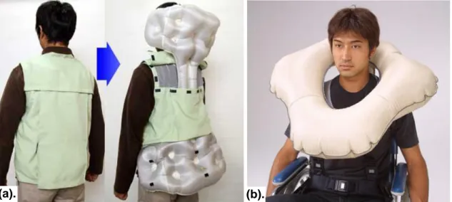
NIIS and Prop Co. Itsumo (Always) Safety Life Jacket
Aside from sporting applications, suit-based airbag systems have also found use in the workplace. One such application is in personal protective equipment in the construction site. To protect construction workers from the effects of falling from altitude, the NIIS and Prop Company in Japan have developed the Itsumo (Always) Safety Jacket. Contrasting to the previously discussed motorcycle jackets, the Itsumo system can be fitted within a relatively compact construction vest, due to its relaxed requirement of only protecting against back-first falls. During a fall, a series of accelerometers within the vest detects the corresponding dynamic conditions and sends a signal to trigger a CO2 gas cartridge, also located inside the vest. This in turn inflates a tubular airbag around the neck, spine, and waist, cushioning the wearer from the impending impact.
Figure 2-4: The Itsumo Safety Life Jacket [15]
This same design concept has also formed the basis of other wearable-airbag products developed by the NIIS and Prop Company. These include the Kiruair (wearable airbag), an airbag-vest intended for use by elderly people with epilepsy who are susceptible to sudden and dangerous falls; and the Piabaggu, an airbag system designed to protect the wheelchair bound during falls. These are shown in Figure 2-5.
2.1.2 Seat-Based Airbag Systems
Seat-based airbag concepts refer to those which consist of airbags being either installed onto, or acting as a seat. Traditionally, these systems have been designed for recreational use, and hence have been optimized primarily for comfort. Even though this is the case, some guidance and inspiration for the conceptual design of a personal airbag system can still be acquired. Notable examples of such concepts are presented in the following sections.
Inflatable Seats
One of the first patents filed for an airbag seat type system was made in 1987 by Diane Hull [16]. Intended as a floatation device for use in recreational purposes, this concept consists of two stacked annular shaped airbag chambers connected to an inflatable back rest and seat cushion. In addition, each chamber is independently inflated prior to use, allowing for the entire system to remain afloat in the case that one is ruptured. This concept is shown in Figure 2-6.
(a). (b).
Figure 2-5: Suit-Based Airbag Systems marketed by the NIIS and Prop Company of Japan (a). Pre- and post-inflation of the Kiruair [14]
Figure 2-6: Inflatable Seat Concept [16]
Although intended for a different purpose, this multi-chamber concept is applicable to a personal airbag system in that there is a level of redundancy built into the concept. This is particularly important during the execution of the life-critical function that is the attenuation of landing loads. Furthermore, the fact that the annular shape of the airbags is designed to maintain buoyant stability is also of interest. This is because such an attribute can be related to system stability under varying impact angles, which can in turn equate to an improvement in the overall robustness of the system.
Inflatable Seat Cushions
This is a variant of the inflatable seat concept, where inflatable components are installed on a standard, rigid seat. Generally, these concepts have found use in aircraft, automobiles, and trucks, where long duration back and neck support, as well as vibration mitigation are desirable. Displayed below are two selected inflatable cushion-based concepts:
Figure 2-7: Inflatable Seat Cushions (a). Seat Integrated Inflatable Neck Support [17] (b). Inflatable Seat Cushion and Body Support Assembly [18]
(a). (b).
Upper Chamber Handle
Seat Cushion Back Rest Cushion
Inflation Valve Lower Chamber Safety Belt
Here, it can be seen that these cushion-based concepts are inherently easy to implement onto existing seating systems, hence providing potential retrofitting capabilities onto existing system designs. Additionally, the neck and head support provided by the concept depicted in Figure 2-7(a) facilitates protection against rapid head and neck movements, one of the areas in which people are most fatally susceptible to during impacts. Furthermore, the separated inflatable chambers in the concept shown in Figure 2-7(b) also allows for customized support of the occupant’s back by varying the pressure distribution across the chambers. This also contributes to improving ergonomic aspects of the system, namely occupant comfort.
Seatbelt Mounted Airbags
Seatbelt mounted airbags involve the implementation of airbags within seatbelts worn by the occupant of a vehicle. They have gained popularity in recent times, especially in general and commercial aviation applications, due to a more stringent requirement for seat strength released by the Federal Aviation Administration in late 2009 [19]. Specifically, seatbelt mounted airbags provided an elegant design solution to protecting passengers sitting behind rigid bulkheads during aircraft accidents, where it was not possible to install any other form of impact attenuation device [20]. An example of this is shown below in Figure 2-8.
Figure 2-8: Amsafe Commerical Aviation Seatbelt Airbag [21]
Like the airbag concepts described in Section 2.1.1, seatbelt mounted airbags are triggered to inflate by a series of sensors which senses the conditions governing an
impending impact. As the airbags inflate, they fill in the space between the passenger and the aircraft bulkhead, thereby providing a means of cushioning the impact between the passenger’s head and the aircraft.
In addition to aircraft, seatbelt based airbag systems have also been implemented in road vehicles. A prime example is the Inflatabelt, a product developed and marketed by BAE Systems under their Vehicle Safety Products group [22]. Instead of cushioning against impacts with a hard surface, Inflatabelts act to restrain the motion of the occupant’s torso, particularly in the forward and lateral directions. Moreover, relative restraint between the torso and upper thighs is further provided to prevent straining of the lower back. Figure 2-9 displays some of the Inflatabelt concepts developed by BAE:
Figure 2-9: Inflatabelt Concepts developed by BAE Systems [22] (a) Original Inflatabelt Concept (b) The SMART-Belt (c). The SMART 4
2.1.3 Cabin-Based Airbag Systems
Ever since the early 1990’s, when the implementation of airbags into automobiles became widespread, cabin-based airbag systems have become by far the most commonly recognized form of airbag implementation. In addition to being installed internal to a cabin, airbag systems have also been implemented to the exterior of the cabin of a vehicle. Both of these concepts will be further discussed in the following sections.
In-Cabin Airbag Systems
In the 1970s, as the driving population began to proliferate, the need for automotive safety became increasingly apparent. In response to this, car manufacturers began to first implement airbags within the steering wheel of their vehicles to protect the heads of passengers from
heavy impacts during accidents. Since then, the value of this innovation in saving lives has become increasingly recognized, inspiring its widespread use throughout other areas of the car interior. Notable examples of such regions include the side and windows, as can be seen in Figure 2-10.
Figure 2-10: Airbag system in a 2007 Model Honda Accord automobile consisting of steering wheel mounted, side, and side curtain airbags [23]
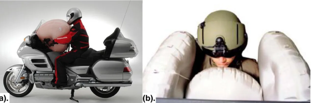
In addition to automotive applications, airbags have also gained popularity in other terrestrial vehicles, with well-known examples being within the cabin of helicopters and motorcycles.
Figure 2-11: Airbag Applications in Terrestrial Vehicles (a). The Honda Gold Wing
Motorcycle Airbag System [24] (b). The BAE Systems Cockpit Airbag System, now implemented on all U.S. Army UH-60A/L Black Hawk and OH-58D Kiowa Warrior helicopters [25]
In all of these applications, the underlying technologies employed have been virtually the same. As the vehicle is subjected to an impact, a network of sensors located throughout the vehicle sends data to a central control unit, which then commands a gas generator to inflate an airbag. Basic versions of this sensor suite include accelerometers, gyroscopes, and seat occupancy sensors; while more advanced automotive multi-airbag systems include impact sensors, wheel speed sensors, brake pressure sensors, and door pressure sensors. These more advanced sensor suites act to ensure that the appropriate combination of airbags is inflated, according to the location and severity of the impact [24-26].
Out-of-Cabin Airbag Systems
Contrasting to their in-cabin counterparts, out-of-cabin airbag systems have seldom seen use in terrestrial vehicles. Part of this is because scenarios in which such a system would be ideally suited to, are uncommon in terrestrial vehicles. One example of such a scenario is the cushioning of falling objects, such as aircraft crew escape capsules, from the impact loads incurred during an emergency escape or landing.
The most notable example of such an implementation is within the crew escape module of the F-111 fighter aircraft, as seen in Figure 2-12.
Figure 2-12: F-111 Crew Escape Module Airbags (a). Drop Testing at NASA Langley Research Center [27] (b). Detail of Airbag Configuration [28]
During an emergency ejection scenario, a series of charges is triggered around the escape module to separate it from the aircraft fuselage. Shortly after, a small rocket motor in the
(a). (b).
Blow Out Plugs
compartment is activated to separate the capsule from the falling aircraft. Once the capsule is clear from the aircraft, a parachute is deployed, triggering a switch to commence the inflation of an airbag located on the underside of the capsule. Constructed of neoprene coated nylon cloth, this airbag consists of several interconnected chambers inflated by compressed nitrogen bottles stowed within the escape capsule. During impact, blowout plugs located on the side of the airbag are released, venting gas and reducing the shock loads on the module to within allowable limits.
More recently, airbags have been implemented into the undercarriage of helicopters to limit impact loads to the crew and damage to the airframe during crashes. Like those of the F-111 escape module, these airbags also release gas through vents during impact to facilitate improved load attenuation. The degree to which these vents release gas is dependent on the surface being impacted upon, as determined by the frequency content of the returning signal emitted from a proximity sensor. During water landings, the vents are commanded to remain closed, thus providing floatation for the cabin, in addition to impact attenuation [29]. Figure 2-13 shows some examples of out-of-cabin airbag systems used in helicopter applications.
Figure 2-13: Helicopter Out-of-Cabin Airbag Systems (a). The Rafael Rotorcraft External Airbag Protection System (REAPS) undergoing a drop test [30] (b). The Aero Sekur Hard-Landing Helicopter Inflation System Concept displayed at the 2010 Farnborough Airshow [29]
2.1.4 Summary of Relevant Terrestrial Airbag System Concepts
In reviewing the various terrestrial airbag system concepts several lessons can be learned which can influence high level architectural decisions in the design of a personal airbag
system. A common concept which has appeared consistently thus far is the use of active systems. That is, those which employ sensors to trigger the rapid inflation of a set of airbags via a gas canister or a gas generator. In all of these cases, the airbags are fully inflated within 30-80 milliseconds from the moment of actuation, allowing for the system to be fully deployed prior to impact. The need for this rapid inflation arises from the uncertain nature of the impacting event, which is especially so in terrestrial settings, such as vehicular accidents and accidental falls by construction workers and the elderly. Conversely, in the spacecraft landing scenario, the time of an imminent landing is typically known beforehand. Because of this, a personal airbag system can be inflated well in advance of landing, thus negating the need for a complex inflation system.
Another observation made from this review is the importance of providing comfort and support to the occupant’s back and neck. This was especially highlighted by the seat-based airbag concepts. In these systems, back support was provided by incorporating a multi-chambered airbag system which conformed to the occupant’s back. In addition, neck support, as was also provided by all reviewed suit-based airbag concepts, was facilitated by a pressurized airbag situated around the neck and shoulders. The fact that this was a ubiquitous attribute highlights the importance of including a means to limit the relative motion between the head, neck, and shoulder in the design of a personal airbag system. This is especially important as this relative motion is a primary cause of fatal head and neck injuries during impact events [31].
Furthermore, upon review of the out-of-cabin airbag system concepts, explicit inclusion of venting was also observed. As will be discussed in Section 3.1.1, venting of gas from the airbag aids in improving impact attenuation performance by effectively removing energy from the system. This is particularly critical when the mass of the object is large, as is the case with the 3000lb escape module and the helicopter out-of-cabin systems presented.
Hence in summary, the following observations, relevant to the conceptual design of a personal airbag system, were made in the review of past and present terrestrial airbag systems:
Actively actuated airbag systems are not necessary when the time of impact is known well in advance
It is important to limit relative motion between the head, neck, and shoulders during an impact as this is a primary cause of fatal injuries
Comfort is an important factor when designing a seat, especially when the occupant is expected to sit within it for long periods of time. One characteristic of a comfortable seat is its conformance to the occupant’s back; and
The inclusion of venting mechanisms within an airbag aids in its ability to attenuate impact loads
2.2
Spacecraft Airbag Systems
It is interesting to note that airbags have been consistently considered as viable options for landing attenuation systems in spacecraft since the start of the U.S. and Soviet space programs, when the need for safely returning a vehicle from space first became apparent. More recently, the European Space Agency has also commenced the development of airbag-based landing technique for use in its missions. This section presents the details of these spacecraft airbag systems in an attempt to gain more insight into the design of a personal airbag system.
2.2.1 Project Mercury
In response to the rapid development of Soviet technological capability in space, Project Mercury was initiated in 1959 as NASA’s first human spaceflight program. A key feature of the landing system of the Mercury spacecraft was the inclusion of a passive airbag installed in a skirt between the heat shield and the capsule. As the capsule traveled through the atmosphere prior to impact, the heat shield would be separated and air would be drawn through holes in the skirt. This air would then fill the airbag, which upon impact would be forced back out through the same holes in which it entered; in a venting process similar to that discussed in Section 2.1.3 [4]. Figure 2-14 shows this airbag deployment sequence.
Figure 2-14: Mercury Landing Airbag System (a). Deployment Sequence [4] (b). Detail of Landing Airbag Post-Landing [32]
2.2.2 Luna 9 and 13
Airbags were also prominent in the early days of Soviet space exploration, with the Luna 9 lunar lander, in February 1966, using airbags to achieve the first ever soft landing of a human-made vehicle on an extraterrestrial planetary body. This system involved completely enveloping the spacecraft in a protective airbag layer at an altitude of 75km above the landing site, 48 seconds before impact. While the airbags were being inflated during this landing sequence, retrorockets were fired to slow the vehicle’s velocity from 2.6km/s to 6.1m/s [33]. At an altitude of 5m, contact sensors were activated, commanding the descent engine to shut down and the landing capsule to be ejected. Upon initial contact with the lunar surface, the nitrogen gas inside the airbag compressed and expanded, causing the entire system to experience several bounces before finally coming to rest [34]. Figure 2-15 shows this entire landing sequence.
![Figure 1-5: Three Level Spiral Model used for this Development Effort (Adapted from [10])](https://thumb-eu.123doks.com/thumbv2/123doknet/13913272.449095/31.918.166.749.530.1011/figure-level-spiral-model-used-development-effort-adapted.webp)
![Figure 2-3: Mugen Denko marketing image explaining the functionality of the Hit-Air Shock Buffering System [14]](https://thumb-eu.123doks.com/thumbv2/123doknet/13913272.449095/37.918.201.712.726.1024/figure-mugen-denko-marketing-explaining-functionality-shock-buffering.webp)
![Figure 2-24: Soviet Shock Absorbing Seats (a). The backup Voskhod 1 crew training in their Elbrus couches [50] (b)](https://thumb-eu.123doks.com/thumbv2/123doknet/13913272.449095/57.918.181.736.792.1036/figure-soviet-shock-absorbing-voskhod-training-elbrus-couches.webp)