Architecting Space Communication Networks
by
Marc Sanchez Net
Submitted to the Department of Aeronautics and Astronautics
in partial fulfillment of the requirements for the degree of
A
Master of Science in Aeronautics and Astronautics
OF TECHNOOGYat the
JUN
16 201
MASSACHUSETTS INSTITUTE OF TECHNOLOGY
LIBRARIES
June 2014
@
Massachusetts Institute of Technology 2014. All rights reserved.
Signature redacted
A u th or ...
.
...
Department of Aeronautica nAstronautics
May 22, 2014
Signature redacted
C ertified by ...
Prof. Edward F. CrawleN)
Professor of Aeronautics and Astronautics and Engineering Systems
Thesis Supervisor
Signature
redacted-Accepted by...
...Prof. Paulo
d.
Lozano
Associate Professor of Aeronautics and Astronautics
Chair, Graduate Program Committee
Architecting Space Communication Networks
by
Marc Sanchez Net
Submitted to the Department of Aeronautics and Astronautics on May 22, 2014, in partial fulfillment of the
requirements for the degree of
Master of Science in Aeronautics and Astronautics
Abstract
Reliable communication and navigation services are critical to robotic and human space missions. NASA currently provides them through three independent and un-coordinated network that consist of both Earth-based and space-based assets, all managed under the Space Navigation and Communication Program. Nevertheless, the ever increasing mission requirements and funding limitations motivates the need of revising the current network architectures in order to identify areas of potential performance and cost efficiency improvements.
The main objective of this thesis is to present a tool that helps decision-makers during the process of architecting a space communication network by (1) systemat-ically enumerating and exploring the space of alternative network architectures, (2) identifying those with better performance and lower cost, and (3) providing trace-ability between the outputs of the tool and the architecting decisions. The tool is tailored to the high level design of near Earth space communication networks that support robotic and hurian activities in the Earth vicinity through a set of relay com-miunication satellites and their supporting ground stations. The decisions available to the network architect (both technical and contractual) are presented and along with their couplings.
The tool is validated by comparing it to NASA's Space Network. The current operations of the system are analyzed and used as the baseline case for the validation process. Results demonstrate that the both performance model and spacecraft design algorithm are accurate to less than 10%, while the cost module produces estimates with a 15% error.
Finally, the utility of the tool is demonstrated through three case studies on the evolution of the Space Network. In particular, the impact of new radio-frequency and optical technology to increase the system capacity is analyzed based oi the predicted demand for the 2020-2030 decade. Similarly, the savings of flying relay transponders in commercial satellites as hosted payloads are quantified and benchmarked with respect to NASA's current approach of procuring and operating the entire network. Lastly, the tool is used to compare the current Space Network bent-pipe architecture with a constellation of satellites that takes advantage of inter-satellite links to provide
full coverage of low Earth orbits with only one ground station.
Thesis Supervisor: Prof. Edward F. Crawley
Acknowledgments
This thesis is the result of two amazing year of collaborative work in the System Architecture Lab. I want to first thank Dani, Bruce and Ed for all their support and valuable insights. Neither the work that I have done, nor the passion I have put into it would have been possible without your guidance, help and encouragement. I have really enjoyed every moment that we have shared, be it at MIT or somewhere else in our numerous trips.
I also want to acknowledge all my other friends in the lab - Peter, Morgan, Iigo, Alessandro, Francisco, Alexander and John -, in 409 - Patricia, Paul, Narek, Sreeja, Sydney, and Ioana - and around campus - Ana, Hector, Alexandra, Roberto, Fer-nando, Ada, Carlos. You are a fundamental part of what it means for me to be at MIT and Boston, and I can hardly imagine going through these past two years without you. For those of you who are leaving us, all the best of luck in your future endeavors, you will be very much missed!
Thanks to Jim Schier, Bernie Seery, Antonios Seas, Greg Heckler and David Milliner. It has been a pleasure to work side by side with you as part of the SCaN program.
Romina, you have been the best source of support and affection that I could have ever wished for. These last eight months have been a mix of great moments, incredible experiences and unforgettable memories.
Finally, I would like to thank my family and in particular my mother. You have always encouraged me to be ambitious, curious and hardworking, and this has been key to the success of this thesis and all previous accomplishments I might have had.
Contents
1 Introduction
1.1 Background and motivation . . . .
1.1.1 History of NASA's space communication networks . 1.1.2 M otivation . . . . 1.2 System Architecture . . . .
1.2.1 Tools for System Architecture . . . .
1.3 Generic problem statement . . . . 1.4 Architecting space communication networks . . . . 1.4.1 Network simulators . . . . 1.4.2 Point designs . . . . 1.4.3 Architecture studies . . . .
1.4.4 Tradespace exploration . . . .
1.5 Specific problem statement . . . .
1.6 Thesis overview . . . .
2 The 2.1
Space Network Architecting Tool Introduction ...
2.2 Decisions to architect a space communication network 2.2.1 Network topology . . . . 2.2.2 Business model . . . .
2.2.3 Network technology . . . .
2.3 SNAT architectural decisions . . . .
2.4 Model overview . . . . 15 . . . . .15 . . . . . 15 . . . . . 17 . . . . . 18 . . . . . 20 . . . . . 21 . . . . . 22 . . . . . 23 . . . . . 24 . . . . . 25 . . . . . 26 . . . . . 27 . . . . . 28 29 . . . . 29 . . . . 29 . . . . 31 . . . . 32 . . . . 34 . . . . 35 . . . . 37
2.5 Model description . . . . 2.5.1 The VASSAR framework .
2.5.2 Space and ground segment
2.5.3 Network evaluator . 2.5.4 Cost estimation . . . . 2.5.5 Search engine . . . . design 3 Validation of SNAT 3.1 Introduction . . . . 3.2 Validation strategy for the performance model 3.3 Validation of the performance model . . . . . 3.3.1 Dataset description . . . . 3.3.2 Definition of network metrics . . . . . 3.3.3 Analysis of TDRSS operational data 3.3.4 Validation of the scheduling algorithm 3.4 Validation of the spacecraft design algorithm 3.5 Validation of the cost model . . . . 3.6 Tradespace validation . . . .
4 Evolving NASA's Space Network
4.1 Introduction . . . . 4.2 Network customer characterization . . . . 4.3 Case study 1: Valuation of new technology and hosted payloads
4.3.1 Tradespace definition . . . . 4.3.2 Results: Infusion of new RF and optical technology . . .
4.3.3 Results: Procurement vs. hosted payloads . . . . 4.4 Case study 2: Valuation of inter-satellite links . . . . 4.4.1 Tradespace definition . . . . 4.4.2 R esults . . . .
. . . .
39
. . . . 40 . . . . 41 . . . . 49 . . . . 61 . . . . 67 69 . . . . 69 . . . . 70 . . . . 70 . . . . 70 . . . . 72 . . . . 74 . . . . 83 . . . . 85 . . . . 88 ... . . . . .. . . . . 88 91 91 91 94 94 97 100 103 103 1055 Conclusions
111
5.1 Thesis sunmary . . . 111
5.2 Main contributions . . . . 113
5.2.1 Methodological anid modeling contriibutions . . . . 113
5.2.2 Findings from the case stU(lies . . . . 114
List of Figures
Notional space of architectures . . . . Model overview . . . . Example of a tradespace from SNAT . . . .
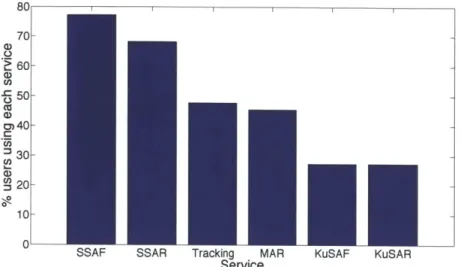
Spacecraft design algorithm. . . . . Architecture satisfaction decomposition . . . Lifecycle cost breakdown . . . . TDRSS daily data volume and service time . TDRSS number of granted contacts . . . . . Network level statistics . . . . M etrics vs. service . . . .
Service popularity . . . . Scheduled time per satellite . . . .
Data volume per satellite . . . . Single Access antenna utilization . . . .
Scheduled contact data rate distribution . . Evolution of the network capacity . . . . Tradespace definition . . . . Transponder selection . . . . Transponder allocation . . . . Evolution of a procured Space Network . . . Procurement vs. Hosted payloads . . . .
4-6 Combinations of procured and hosted payloads .
2-1 2-2 2-3 2-4 2-5 2-6 3-1 3-2 3-3 3-4 3-5 3-6 3-7 3-8 3-9 3-10 4-1 4-2 4-3 4-4 4-5 . . . 30 . . . 38 . . . 39 . . . 44 . . . 62 . . . 62 75 75 76 77 78 79 79 81 83 89 . . . . 96 . . . . 99 . . . . 100 . . . . 101 . . . . 102 102
. . . .
. . . .
4-7 Number of hosted payloads per satellite . . . 104
4-8 Benefit-cost tradespace . . . 106
4-9 Detail of the number of satellites and ground stations . . . .. 108
List of Tables
2.1 Architectural decisions . . . . 2.2 Correction factors for ISL and SGL data rates . . . . 2.3 AV required to compensate drag for different orbits . . . . 2.4 AV required for ADCS . . . . 2.5 CERs coefficients for thermal, avionics, and structure subsystem 2.6 Scheduling Algorithin Facts . . . . 2.7 Scheduling Algorithm Heuristics . . . . 2.8 Extract of launch vehicle database . . . .
3.1 3.2 3.3 3.4 3.5 3.6 3.7 3.8 3.9 4.1 4.2 4.3 4.4 Satellite utilization . . . . SN nominal data rates . . . . Validation of %Ut for a typical day of operations Validation of DVtal for a typical day of operations Validation of %Ut for a high load scenario . . . . . Validation of Dt,t,, for a high load scenario . .
Error on mass and power estimates for TDRS-J Error on mass fraction estimates for TDRS-J . . . .
Error on cost estimates . . . . Detailed user scenario . . . .
Case study architectural decisions Case study architectural decisions Pareto front architectures . . . .
36 42 46 46 49 55
59
65 . . . . 78 . . . . 82 . . . . 85 . . . . 85 . . .. . . . . . 86 . . . . 86 . . . . 87 . . . . 87 . . . . . . . 88 93 97 106 107Chapter 1
Introduction
1.1
Background and motivation
1.1.1
History of NASA's space communication networks
In 1956, the Space Studies Board of the National Academy of Sciences approved a plan by the Smithsonian Astrophysical Observatory to establish an optical tracking network to track the first American satellites [43]. In a few years, 12 optical ground stations were built around the world. The utility of these stations was limited due to the low degree of automation in the acquisition of targets. Microwave interferometric satellite tracking stations (Minitrack) were also developed in the 1950's. Minitrack was the primary Tracking, Telemetry and Command (TT&C) network for NASA during most of the late 1950's and early 1960's providing service to both Explorer 1 and Vanguard 1 missions.
In 1958 the National Aeronautics and Space Administration (NASA) was created in order to accelerate the pace of space exploration and start ambitious manned and unmanned programs. After Alan Shephard became the first American in space in 1960, the launch rate of unmanned and manned spacecraft started to grow, thus im-posing tighter requirements on the Minitrack network. This caused the development of the higher performing Satellite Tracking and Data Acquisition Network (STADAN) in the early 1960's, which used 12-meter and 26-meter S-band antennas for TT&C.
Active tracking systems such as the Goddard Range and Range Rate (GRARR) were also developed as the passive interferometric systems were unable to track satellites in highly eccentric or high altitude orbits. Satellite Automatic Tracking Antennas (SATAN) were installed in order to enable data downlink for high data rate space-craft. As NASA started to launch satellites into polar orbits, new ground stations such as Tananarive were added to support these new types of customers.
With the start of NASA's human spaceflight program (HSF) - Mercury, Gem-ini and Apollo programs - the Manned Space Flight Network (MSFN) was created. This new network complemented the already existing STADAN that provided service mainly to robotic missions. With the combination and expansion of the two, the use of the Minitrack network tampered off.
In 1971, after the end of Skylab, the STADAN and MSFN networks were consol-idated into a single network, the Spaceflight Tracking and Data Network (STDN). It then became clear that using ground assets exclusively was not enough to meet the user requirements (especially those of manned spaceflight) due to line-of-sight con-straints. The solution to this was to incorporate space assets to the network, namely the Space Network (SN), which includes a constellation of GEO satellites known as the Tracking and Data Relay Satellite System (TDRSS), and the supporting ground terminals in White Sands and Guam.
The first generation of TDRS was conceived in the early 70's to replace the MSFN. TDRSS' maiden launch occurred on April 4th 1983. Seven first generation TDRS satellites (TDRS-1 through TDRS-7) were launched between 1983 and 1995 into GEO orbits, although TDRS-2 never reached orbit as it was destroyed in the Challenger disaster. The second generation of TDRSS started with the launch of TDRS-8 in 2000, with two more satellites (TDRS-9 and TRDS-10) added in 2002. Finally, the third generation of TDRSS is currently being deployed, with TDRS-11 and TDRS-L launched in 2013 and 2014 respectively, TDRS-M scheduled for launch in 2015 and TDRS-N as a possible extension to the network by 2016.
On the other hand, the ground segment of STDN became the Near Earth Net-work (NEN). The current NEN consists of six NASA-operated and ten commercially
operated ground stations featuring a broad range of antennas between 4 and 18 me-ters. These antennas are spread across the world, both in latitude and longitude, to provide contact opportunities to any LEO mission regardless of its inclination.
Finally, the last NASA owned and operated network is the Deep Space Network. It was created in the late 1950's with the goal of providing TT&C services to un-manned interplanetary missions. The DSN has been managed by the Jet Propulsion Laboratory (JPL) since its inception, and currently has three sites in Goldstone, Madrid, and Canberra with several 34-meter and one 70-in parabolic antenna. The three ground stations are approximately 120deg apart in longitude to provide full coverage, with the first two sites servicing the northern hemisphere and the last one operating in the southern one.
1.1.2
Motivation
Providing communication and navigation services is crucial to the success of any space mission. Since the start of the US space program, NASA has continuously developed and upgraded multiple networks of ground and space-based antennas that provide radio-frequency (RF) communications to spacecraft orbiting the Earth and in deep space. This networks have evolved to three independent set of assets, the Near-Earth Network (NEN), the Space Network (SN) and the Deep Space Network (DSN).
In 2006, the Space Communication and Navigation (SCaN) program was assigned management and systems engineering responsibilities for the SN, the NEN, and the DSN. The main rationale for this policy decision was to ensure that the architecture of the three formerly independent networks would evolve sinergistically to converge into a unified network that meets the needs of all user communities within the next decades. Since then, the SCaN program office has started multiple studies to explore architecture options for the SCaN network.
One of the first pieces of work within them has been the evolution of the SN and its TDRS satellites. Although the current system has been highly successful over the last thirty years, current funding limitations call for cheaper ways of maintaining and upgrading the network. As a reference, the SN operates approximately on a 10 year
replenishment cycle, with three new satellites being launched each time. Based on the 3 rd generation of TDRS, the cost of two satellites plus ground station upgrades is
$715M 1 approximately [2]. Additionally, NASA spends $40M a year in operational costs, thus giving a total estimate of $1.8B every 10 years.
Given that the SN is an expensive system, one should ask whether the current architecture is still the best alternative to meet the future demand and, at the same time, meet the expected budget limitations. Several technical and non-technical fac-tors challenge this assertion. For instance, new RF and optical technology can be coupled with higher on-board processing capabilities to provide higher data rates with smaller transmit power and, therefore, simpler and cheaper satellite buses. Fur-thermore, communication payloads can be also be placed in commercial spacecraft as hosted payloads, thus reducing the cost of the system as, neither the bus nor the launch vehicle have to be directly procured and paid for. These facts indicate that it is necessary to revise the architecture of a system like the SN and understand what changes can be made in order to optimize its performance and ensure its affordability within the SCaN program.
1.2
System Architecture
System Architecture as a discipline was conceived in the late 80's as a spin off of civil engineering. Since then, several other fields have embraced its methodologies and proven it successful. For instance, both aerospace and communication industries have applied it in the earliest phases of the design of complex systems [27].
The foundations of System Architecture lay in the principles of System Engineer-ing, which considers a system as a combination of interacting elements oryanized to achieve one or more stated purposes [22]. Systems Architecture is a phase within the
Systems Engineering practice in that it provides a framework to outline the high level design of a system and understand what decisions are important in order to meet the needs of those will eventually use it. In that sense, the architecture of the system
can be thought of as the set of decisions that define its highest level design [44] and, in doing so, constrain the space of alternative designs and determine the majority of the system performance and cost.
Crawley defines a system architecture as "the embodiment of a concept: the al-location of physical/informational function to elements of form, and the definition of interfaces among them and with the surrounding context" [12]. This definition is based upon four main concepts: First, the function is what the system does to an external party in order to satisfy its needs. Second, the form is what the system is, i.e. its physical or informational representation; it is the sum of its elements and their structure. Third, the concept is the vision or mental model that helps humans understand how the system functions are performed with the available elements of form. And fourth, the interfaces are the connections between the system and its environment.
With these definitions and framework in mind, the architecture becomes the em-bodiment of the concept, the materialization of the mental model into a system that is implementable in the real world. Additionally, understanding the definition of a good architecture implies determining the sources of associated benefit and cost. Crawley argues that the benefit is delivered to an external party through the function of the system while the cost arises from its form. Being that the case, the value of the architecture can be measured as the benefit perceived by the external party given its cost.
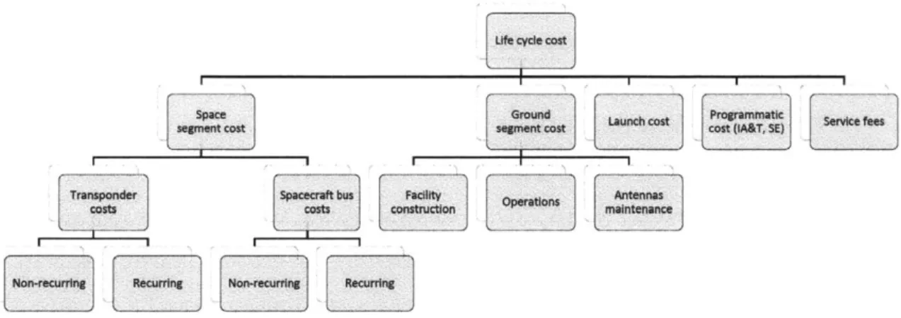
In order to compare one architecture to another and determine which is "better", the system architect must specify which are the suitable metrics to measure benefit and cost. For the latter, life cycle cost (LCC) is generally used as a proxy for the economical investment required to design the system, manufacture it, operate it and finally dispose of it. However, other metrics are also used when not enough infor-mation is available to correctly price the different elements of the system throughout their life cycle (e.g. niumber of development projects, antenna aperture). On the other hand, the definition of metrics to measure performance is highly dependent on the problem at hand since they are, in general, tailored to particular functions that
the system is performing in order to deliver value (e.g. miles per gallon for a car). Finally, once the appropriate metrics have been defined, System Architecture ad-vocates for systematically exploring the space of alternate architectures and under-stand what decisions are important (i.e. drive the system performance and cost), as well as perform trade-off and sensitivity analyses with respect to them and their associated design variables. With this process, System Architecture provides valuable information to the decision-maker by formally informing the process to transform a set of solution neutral requirements to a set of feasible conceptual designs.
1.2.1
Tools for System Architecture
At the highest level, System Architecture has benefited from computational tools for
three main purposes
[35]:
" To provide representation of different aspects and views of the system
architec-ture (e.g. SySML
[45]).
" To simulate the operational behavior of a system architecture using models (e.g.
OPCAT
[33])
" To assist decision-makers during the system architecting process (e.g. OPN [25])
Based on the notions introduced in section 1.2, architecting a system can be con-sidered a decisions making process where the main goal is to maximize the delivered value by the system [44]. This can, therefore, be viewed as an optimization problem in which the architecting decisions are encoded as mathematical variables (continu-ous, discrete, logical) and the system value becomes the objective function. Variables can have lower and upper bounds so that all options in the architectural space are sensible, as well as constraints that capture relationships between them.
Therefore, this thesis is particularly interested in tools of the third type, i.e., tools that (1) can support the decision making process of the system architect and, at the same time, (2) explore the space of alternative designs to highlight those that are
optimal. Simmons uses the term architectural decision support tools to refer to tools that can address the first part of the problem [391. He identifies four desirable aspects that render theim useful to the system architect:
* Representational Aspect: Methods to encode al architecture as a set of
decision variables.
* Structural Reasoning Aspect: Methods to analyze and understand the
structure of the problem and its decision variables.
" Simulation Aspect: Methods to list feasible architectures based on the
con-straints between decision variables and then evaluate them to obtain relevant metrics.
" Viewing Aspect: Methods to represent the output information of the tool in
a way that is easily understandable by the decision-maker.
In turn, Selva introduces the concept of System Architectinq Tools as tools that solve both problems (1) and (2) [44]. He classifies them into decision support tools,
combinatorial optimization algorithms or search and constraint satisfaction algo-rithms. An exhaustive literature review of computational tools for system architecting and how they perform with respect to the previously mentioned desirable aspects can be found in his thesis.
1.3
Generic problem statement
Section 1.1.2 identified and motivated the need for re-evaluating the current SN ar-chitecture. More broadly, this can be interpreted as a need to develop tools that help decision-makers architect space communication networks, analyze them and under-stand the different trade-offs that arise when combining the architectural decisions.
In particular, for the tool to be useful during the system architecting process of space communication networks, it has to include the following properties: First, provide a flexible way to encode a space communication network architecture (i.e.
solve the representational aspect). Second, incorporate a flexible and scalable way to encode the decisions and design variables that characterize the network along with their inter-dependencies (i.e. solve the structure reasoning aspect). Third, provide a mechanism to generate feasible network architectures based on the architectural decisions, design variables and system constraints, and evaluate them with respect to multiple metrics (i.e. solve the simulation aspect). And fourth, implement a mechanism to trace the rationale(s) for the results of evaluating a network architecture (i.e. solve the viewing aspect). Additionally, the tool has to be able to handle and search through a large space of network designs and identify optimal alternatives.
1.4
Architecting space communication networks
Studies related to conceptual design, implementation and simulation of space commu-nication networks are not scarce in the literature. At the highest level, they mainly follow four different approaches to tackle the problem:
9 Network simulators: They model the different network architecture layers (physical layer, data link layer, network layer, and so on) in detail by specifying the protocols used in each of them. Then, they propagate the model in time to understand how data flows through the network and estimate the both point-to-point and end-to-end quality of service.
e Point designs: They specify the design of a set of communication assets and then use analytic expressions to quantitatively assess their performance and suitability with respect to the network requirements. The initial point for the study is generally a baseline architecture based on past designs or experience.
e Architecture studies: They propose multiple architectures for the network and then describe their desirability given the expected customer requirements. In most cases this process is conducted qualitatively, although in some cases the comparisons are partially quantified. The main difference with point designs is
that they do not prescribe a baseline architecture but rather provide a generic exploratory view of the different feasible alternatives.
e Tradespace exploration: They explore a large space of network
architec-tures (hundreds or thousands) and compute approximate metrics of desirability and cost. Then, these results are used to formally analyze the design space, understand trade-offs within the system's performance and cost, and identify architectures that are optimal.
Note that the main trade-off between the four approaches is model fidelity versus breadth in the design space. This trade-off arises from two facts: First, high fidelity models tend to be limited in the set of designs they can evaluate, i.e. they are tailored and optimized for a particular set of architectures but cannot be easily expanded to include other alternatives. Second, assuming that a higher fidelity model requires longer computational time to evaluate, then the number of alternatives that can be evaluated within a reasonable time decreases as the model fidelity increases.
The following sections provide a detailed explanation of each aforementioned cat-egory and highlight the model-fidelity vs. model-breath trade-off. They summarize relevant studies found in the literature and compare them with the desirable proper-ties of a tool to architect space communication networks (see section 1.3).
1.4.1
Network simulators
Network simulators are widely used in the Telecommunication Industry. At the high-est level, they are composed of two main parts: a discrete event simulator that repli-cates the system behavior through time, notifying the network model when its state needs to be updated. And a network model, that specifies the stack of protocols used
by each of the network nodes and, in doing so, defines how information is transmitted
through the network. Although different levels of abstraction for the network model are possible, the most common approach is to define a particular communications protocol for each layer of the OSI network architecture [47].
the nodes of the network will be either space-based (communication satellites) or ground-based (ground stations in the Earth or other planets) an orbital propagator is required to determine their position over time. Then, this information can be used to infer line-of-sight (LOS) occultations. References [231, [6] and [5] present a tool that follows the previously described approach. They integrate two commercial pieces of software, STK [41] and QualNet [32], to obtain high precision simulations for the performance of the SN when it supports LEO spacecraft operations. Reference [46] introduces a similar tool, where the orbital propagator and line of sight analyses are based on custom developed modules, and the network simulator is implemented using NS-II [31].
Network simulators are highly accurate tools to solve the simulation aspect. Some of them also resolve the viewing aspect by providing graphical user interfaces (GUI) that facilitate understanding the results of the simulation and trace the rationale for some metrics. However, they neither address the representational aspect nor the
structure reasoning aspect since they do not include flexible mechanisms to encode
the decisions of the network architecture. As a result, they also do not provide mecha-nisms to search through a space of alternative network architectures. Therefore, they are of limited applicability and usefulness to system architects that aim at conducting fast trade-off analyses and understand the span of feasible designs.
1.4.2
Point designs
Point designs are typically structured as follows: First, they provide a generic vision for the need to architect a space network that supports reliable communications from different parts of the solar system (e.g. Earth commercial satellite system, lunar o Mars relay network, deep space communications). Second, they identify the high level needs of the network customers and provide quantitative requirements that can be used to assess the usefulness of a given architecture. Third, they propose a handful of alternative architectures ( 10), they evaluate their desirability based on both
quantitative and qualitative metrics and they finally propose technical options to implement the system.
Reference [7] is a good example of a point design. It starts by indicating the need for affordable high data rate communications in the Moon vicinity to support the robotic and human exploration activities that were planned within NASA's Constel-lation Program. It then identifies six alternatives to create a lunar relay network and selects one of them for detailed analysis (satellites in inclined polar circular orbit at low altitudes). Next, it proposes a detailed design of the relay satellites by character-izing the communication payloads that they carry and communication technologies and protocols they utilize. Finally, it presents several use cases for the system and qualitatively analyzes the suitability of the network to address their needs.
Reference [9] is another example of a point design that studies architectures to integrate the current NASA networks to support Orion's exploration activities with end-to-end IP communication services. Similarly, [28] describes the evolution of Ka-band space communications for near Earth spacecraft assuming that the network architecture is based on the current design of the NEN. Finally, reference [3] is an example of a point designs for a commercial communication systems that provides broadband mobile services.
Point designs are mainly concerned with the simulation aspect, although they also devote some attention to the representational aspect. In particular, they identify the main characteristics of different alternative architectures without formally specifying the available decisions to the system architect. However, their analyses are tailored to the particularities of the baseline network architecture they study and cannot be applied to explore large spaces of alternative designs.
1.4.3
Architecture studies
Architecture studies provide a broader and more qualitative view of the network architecture than both network simulators and point designs. Their main goal is to frame the problem of architecting a space communications network based on the vision and needs for the system. For instance, [29] is the foundational document that identifies the need to perform architectural studies for a unified near Earth and deep space network. It describes the future needs that will have to be addressed by
such a network and provides high level requirements for the different elements it will have to service. This work is further augmented by [8], [36] and [10], were specific requirements are specified and network protocols are suggested as appropriate.
Therefore, architecture studies generally focus on the representational aspect and
structure reasoning aspect rather than on the simulation or viewing aspect. Their
main concern is to understand the system at hand and what are the sensible al-ternatives given (1) the current and future technology trends and (2) the expected demands and requirements. Despite this fact, reference [21] is the only known study that couples the problem of defining architecture alternatives with that of evaluat-ing them and providevaluat-ing recommendations based on quantitative findevaluat-ings. From the needs for NASA, it identifies four main architectural elements (ground-based Earth element, near-Earth relay element, lunar relay element and mars relay element) and proposes alternatives for each of them. Then it analyses their suitability with respect to both individual (particular to that element) and crosscutting (applicable to the entire network) requirements.
1.4.4
Tradespace exploration
'radespace exploration is usually used to analyze large, complex and costly projects that need to satisfy the needs of several stakeholders with respect to multiple metrics. The framework has its roots in Multidisciplinary Design Optimization (MDO), a branch of Systems Engineering that provides a framework to formally search a space of alternative designs and identify its optimal solutions. Tradespace exploration has been applied in the design of multiple systems arid industries, specially within the aeronautical and aerospace industry.
References [14], [15] and [38] explore the application of tradespace exploration during the design of LEO commercial communication networks. They encode the network architecture as a set of design variables that can take a discrete set of values, and then produce valid architectures by choosing one alternative for each of them. For instance, [15] identifies 5 design variables to characterize an architecture: Orbital altitude, minimumn elevation angle, transmit power, antenna diameter and presence
of inter-satellite links. Based on the range of values that each of them can take, a space of 600 alternative architectures is analyzed to compare their performance (measured as the number of communuication channels available) and life cycle cost. Then, the authors identify the set of non-dominated architectures, i.e. those for which the system capacity cannot be increased without increasing the cost of the system.
On the other hand, reference [24] includes a case study on the design of broadband communication systems using MDO. Different constellation patterns in low Earth orbit, medium Earth orbit or geosynchronous orbit are possible, along with variations of the transmit power and antenna diameter of the satellite's transponders. The space of candidate architectures contains 42,400 alternatives which are evaluated through a combination of the GINA model [371 and parametric functions to size the spacecraft and compute its costs.
The surveyed tradespace exploration methods put emphasis on both the
repre-sentational and structure reasoning aspect, and enable post-simulation analyses that provide useful insights to the decision-mlakers (viewing aspect). They also demon-strate the applicability of the framework in the design of commercial satellite system through simplified numerical models that capture the high level capabilities of the network. Additionally, they take advantage of some sort of search algorithmi to enu-merate large spaces of architectures and identify those that are non-dominated in a multi-objective optimization.
1.5
Specific problem statement
After reviewing the available literature on how to architect and design space commu-nication networks, the following research objective can be formulated:
To identify the space network architecture(s) that better address the needs of
future near Earth space missions by:
1. Characterizing the needs of future space missions with respect to communication services.
2. Identifying and characterizing the set of decisions that define a space commu-nication network.
3. Exploring the space of network architectures defined by combinations of the decisions identified in 1.
Using a tradespace exploration tool that sizes the main elements of the network and evaluates its performance and cost.
1.6
Thesis overview
The rest of this thesis is structured as follows:
Chapter 2 starts by presenting the space of alternative architectures for near Earth space communication networks. It then formally defines the decisions that are available to the system architect and how they are modeled. Next, it provides a description of the tool developed in order to perform tradespace exploration studies in the context of space communications.
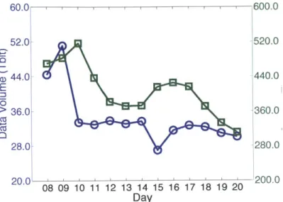
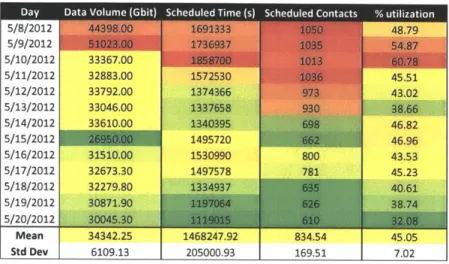
Chapter 3 is devoted to the validation of the tool. It first introduces the validation strategy against NASA's SN and summarizes the main findings of analyzing real SN operational data. Then, it benchmarks the outputs of the performance model with the SN operational data. Finally, it uses the design and cost of the 2nd generation
TDRS to validate both the spacecraft design algorithm and cost model.
Chapter 4 demonstrates the applicability of the tool by creating two case studies on how to evolve the SN. It initially characterizes the missions that are expected to use the system in the future and provides a high level description of the space of plausible network architectures. It then analyzes the evolutionary path for the SN from three perspectives: infusion of new RF and optical technology; choosing new contract modalities to build the infrastructure; and including inter-satellite links.
Finally, chapter 5 summarizes the contributions of the thesis, discusses the iden-tified modeling limitations and proposes areas of improvement and future work.
Chapter 2
The Space Network Architecting
Tool
2.1
Introduction
This chapter offers a detailed description of the Space Network Architecting Tool (SNAT), the newly developed comnputational tool that allows architecting space coin-munication networks that provide service to missions in the Earth vicinity. The chapter is structured as follows: First, a discussion and analysis of the different deci-sions available to the network architect is presented. Each of them is formulated as a combinatorial problem that facilitates the process of enumerating the different archi-tectures. This leads to the tool overview, where the different modules are introduced together with the inputs they require and the outputs they produce.
2.2
Decisions to architect a space communication
network
Section 1.2.1 introduced the notion of formulating a system architecting problem as a decision making process. Therefore, in order to create a tool that assists this process it is necessary to specify what decisions are available to the network architect and
to Fully Connected 0 0. o
e
1-z MRO TDRS 41h Gen. 0Su NOZRF vs. Optical Privately owned
Access Network Capacity
Mcanism ZF pcii
Routing Manual vs. Autonomous
Mechanism
static vs. Dynamic
Hosted Payloads Commercial
Business Model
Figure 2-1: Notional space of architectures
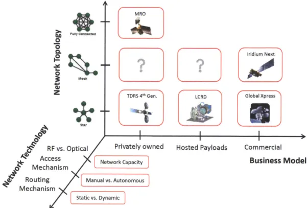
how they are interrelated. Figure 2-1 presents a graphical representation of the main alternatives for the high level design of a space communication network. It structures them in three main axes, network topology, network technology and business model and indicates, when possible, systems already or under implementation that exemplify parts of the design space. For instance NASA's SN can be considered as a star topology network in that all communication channels to and from customer spacecraft are channelized through a TDRS satellite that downlinks the information directly to the supporting ground stations. Alternatively, a constellation of satellites like Iridium Next takes advantage of inter-satellite links send information from one satellite to another satellite thus creating a meshed network. Additionally, the infrastructure is owned by a commercial company that acts as a service provider to NASA and other government agencies.
On the other hand, the network technology axis is related to the communication technologies and protocols used to architect the network. Note that the three
de-Iridium Next
LCRD Global Xpress
picted elements have a one to one correspondence with the three first layers of the OSI model. The RF vs. optical decision can be more broadly represented as the choice of technologies to implement the physical layer of the network, while the ac-cess mechanisms is related to algorithms used to share the RF spectrum and avoid interference (data link layer). Finally, the choice of routing mechanisms is related to the need of ensuring reliable end-to-end communications within an environment with high delays and line-of-sight restrictions.
2.2.1
Network topology
The decisions regarding the network topology are related to physical configuration of the network assets. This translates to two coupled sub-problems: What is the accepted degree of inter-connectivity between network nodes? Where do we place communication assets and how do we configure them?
The first sub-problem leads to two architectural decisions than progressively de-termine the type of topology for the network:
* Fully connected vs. Meshed/Star: If the relay communication payloads are placed on-board the network customers then the network can be considered as a fully connected network. All nodes can talk to each other whenever there is line-of-sight, share information and route it from an origin to a destination. An example of this type of network in space is implemented by NASA to pro-vide communications with the Mars surface. All scientific rovers carry a UHF transponder that connects to a relay transponder on-board the scientific orbiters around the planet, which in turn send the information back to Earth through a more capable X-band link. In contrast, communication payloads can also be placed on-board dedicated satellites that are specifically designed to provide communication services to other missions. This leads to either a meshed or star network and is the approach followed by most space networks nowadays (e.g. NASA's SN, ESA European Data Relay System (EDRS), or any of the connercial satellite communication providers).
* Meshed vs. Star: Assuming that relay communication payloads are placed on dedicated relay satellites, the next decision is related to using inter-satellite links. If that is the case, then the relay satellites can send information to one another thus creating a meshed network that minimizes points of failure. Without these inter-satellite links, all customers have to communicate to a relay satellite which is directly connected to the end terminal on the ground.
Once the topology of the network has been specified, the next step is to define the positions of both the space and ground segment. For the space part, and recalling that SNAT is intended to help design near Earth networks, this is equivalent to the constellation design problem, i.e. selecting the optimal orbital positions to place the relay assets. In turn, the design of the ground segment can be considered as a selection problem in which the goal is to pick the optimal subset of locations to place ground stations in order to maximize support to the relay satellites.
Finally, the last decision related to the network topology is tied to how commu-nication payloads are allocated into relay satellites. For instance, if three payloads operating at different frequency bands are to be launched, is it better to put them all into a single spacecraft or should they be separated so that there is no interference between them. If that is the case, then each orbital position will not contain one but several satellites flying in formation.
2.2.2
Business model
The business model decision intends to capture the trades on how to financially sustain the provision of communication and navigation services for space missions. Prom a historical perspective, the default business model has been direct procurement of all network assets by the entity deploying the infrastructure. For instance, over the last 30 years NASA has bought and then privately operated all the assets of the Space Network - albeit through subcontractors in some cases. This fact has forced the agency to pay for the whole life cycle cost of all network assets.
option is probably "hosted payloads", an approach that allows companies to put sec-ondary payloads on-board satellites that they do not own in exchange for an economic compensation. The owner of the satellite commits itself to provide satellite resources (mass, power, volume from the bus) to that payload and launch it into orbit. As a result, the hosted payload does not need to incur in the cost of designing and man-ufacturing the satellite bus, nor does it have to directly procure the entire launch vehicle. However, it is still responsible for part of the integration and testing cost, as well as the operations cost of the hosted payload.
Despite the attractiveness of hosted payloads from a financial perspective, there are several challenges that hinder their suitability for architecting a space network. For instance, concerns have been raised on how unexpected failures in the host space-craft would affect the hosted payload and the level of service it is providing. This is particularly critical if the hosted payload has to provide contingency communications to other spacecraft, thus requiring a high degree of availability and flexibility. On the other hand, since only a handful of missions have used them in the past, there is little expertise and quantification of the programmatic burden incurred when flying a hosted payload. This is also a problem when negotiating the legal and contractual agreements between the payload and satellite owner.
Finally, the third alternative to obtain communication and navigation services in the Earth vicinity is to take advantage of commercial providers that own a con-stellation of relay satellites. With this alternative an agency like NASA would not have to own any network asset, and instead would have to pay a fixed fee to use the transponders of the commercial operators. Two main drawbacks for these op-tions can be envisioned: First, the commercial providers typically size their network to provide low (kbps) or moderate data rate links (tens of Mbps) to numerous cus-tomners. In contrast, a network that supports space missions is more prone to use a limited amount of links that can be configured to provide very high data rates (up to Gbps). Second, the type of information to send over the network might impose high confidentiality and integrity requirements that cannot be guaranteed by a third-party owned network.
2.2.3
Network technology
The network technology decisions are related to the configuration of the network and the choice of protocols used for providing the communication services. In that sense, the first decision to make is what frequency bands will be supported in the system. This choice has huge implications in the amount of information that can be transmit-ted since there are tight bandwidth allocations and limitations imposed by national and international regulatory organizations (e.g. Federal Communications Commis-sion, National Telecommunications and Information Administration, International Telecommunication Union).
Once the frequency bands have been selected, the next decision is related to the available transponder technology. In particular, traditional systems rely on bent-pipe technology that can only process the RF signal at the analogical level to provide signal filtering, mixing and amplification. Alternatively, newer transponders are able to fully process incoming analog signals by demodulating them, interpreting the digital information at either the frame or the packet level, and finally re-modulate. Based on these differences, three main types of networks can be envisioned:
" Bent-pipe: The relays only process signals at the analogical level. When a transmission is received it is immediately re-transmitted to the next node with which continuous connection is already available.
" Circuit-switched: The relays are able to demodulate the signal and process digital information up to the data link layer. This option allows increasing the link performance since bit and frame error correction techniques can be utilized in the intermediate nodes. However, circuit-switched network do not have buffers to store information and, therefore, immediately re-transmit similar to how a bent-pipe transponder would do it.
" Store-and-forward: The relays can do full processing of the incoming signals, convert them into a bit stream and store the information locally if it is deter-mined that the next hop is not available. They have to implement both routing
and transport mechanisms to ensure that packets reach their end destination reliably. Additionally, they can also implement a bundle layer that offers reli-able communications in high delay environments like space networks. If that is the case, then a Delay Tolerant Network is achieved.
Finally, the last two decisions are related to options regarding the access, routing and transport mechanisms. Since all communication channels within the network uti-lize the same spectrum bandwidth, access mechanisms are required in order to avoid interference between different customers. The classical approach to this problem in the space network community has been to use either scheduled systems or a combi-nation of time, frequency or code division multiplexing (TDMA, FDMA or CDMA). Similarly, if the network under consideration is store and forward then it is necessary to select the appropriate routing an d transport mnechan isns to support its operation.
2.3
SNAT architectural decisions
Section 2.2 presented an overview and discussion of all high level decisions that are needed in order to architect a space communication network. Although SNAT aims at capturing the entire space of alternative designs, data and modeling limitations restrict its applicability by making the following assumptions:
" All communication payloads are placed in relay spacecraft effectively eliminating
fully connected networks.
* The access media scheme will be based on a scheduled system. This assumption comes from the fact that all networks that provide service to space missions (SN,
NEN, DSN, EDRS, and so on) utilize this type of access mechanism.
* The routing and transport mechanisms will be assumed to be ideal. In other words, if a customer connects to the network, then the information that is being sent will reach its destination seamlessly and reliably.
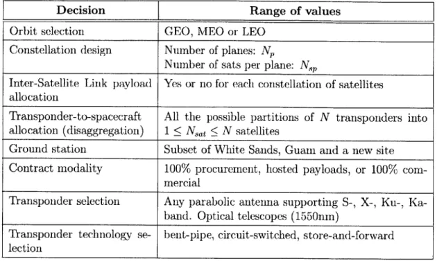
As a result, the set of available decisions to architect the system and their corre-sponding values are presented in table 2.1.
Decision
Range of values
Orbit selection GEO, MEO or LEO
Constellation design Number of planes: N,
Number of sats per plane: Np
Inter-Satellite Link payload Yes or no for each constellation of satellites allocation
Transponder-to-spacecraft All the possible partitions of N transponders into allocation (disaggregation) 1 < Nat < N satellites
Ground station Subset of White Sands, Guam and a new site Contract modality 100% procurement, hosted payloads, or 100%
com-mercial
Transponder selection Any parabolic antenna supporting S-, X-, Ku-, Ka-band. Optical telescopes (1550nn)
Transponder technology se- bent-pipe, circuit-switched, store-and-forward lection
Table 2.1: Architectural decisions
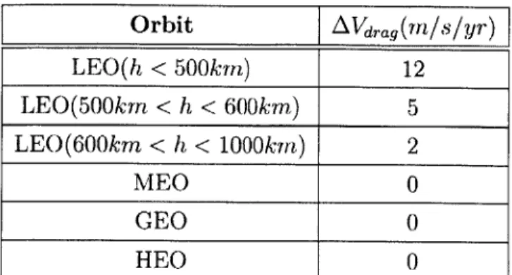
The orbit selection and constellation design are two coupled decisions that dictate the orbital positions where network assets will be placed. For instance, a particular architecture can be based on GEO-1-3 constellation augmented by a MEO-1-1 con-stellation. This means that three clusters of satellites will fly in geosynchronous orbit with a longitudinal separation of 120 deg. Additionally, another constellation of only cluster will fly in medium Earth orbit. For the geosynchronous case, the inclination of the orbit is assumed to be 0, while for MEO and LEO it becomes a variable that the user can specify.
Once the number of constellations and their shape has been defined, the next step is to select whether each of them will have an inter-satellite link (ISL). Each constellation is completely independent in that regard, thus enabling networks where the satellites in the GEO-1-3 constellation carry ISLs, while the MEO-1-1 satellite does not.
Similarly, the set of ground stations to support the space segment of the network has to be selected. This can be done from a sub-set of predefined ground stations. If the selected one already exists, this will be reflected in the system cost by setting
its construction cost to 0. Alternatively, if the site has to be built, then both the construction and operation cost will be accounted in the life cycle cost estimate.
Next, the contract modality for the network is chosen. Similar to the ISL decision, each constellation can have a different contract modality. As a result, the GEO-1-3 can be 100% procured while the augmentation transponder flying at MEO-1-1 can be a hosted payload. The cost of the two constellations will be assessed independently, thus quantifying the cost of flying the augmentation system as hosted in a commercial satellite.
The next two decisions capture the alternatives in transponder selection and how to place it on orbit. The first choice is related to the supported transponders, what band they utilize and what are their nominal data rates. This decision is done at the constellation level, thus enabling networks where the GEO-1-3 constellation is supporting RF communications, while the augmentation system MEO-1-1 is based on an optical telescope.
Finally, the last decision is related to the transponder technology. This is done at the network level, so all the constellations will have the same alternative: bent-pipe, circuit-switched or store-and-forward.
2.4
Model overview
Figure 2-2 presents an overview of the high level structure of SNAT. Two main types of inputs are required in order to explore the space of architectures defined by the decisions presented in the previous section:
* Tradespace definition: It defines the subset of decisions that are selected to
architect the network, along with their allowable values. For instance, in figure 2-2 only two decisions have been selected, transponder selection and antenna allocation. Four antennas have been defined, a TDRS-like antenna with a 5 meter dish and supporting communications at S, Ku and Ka-band. A fast and slow RF antenna, both with 5 meter dishes but one supporting high data rate communications at Ku and Ka-band, and the other one only supporting S-band.
Inputs Tradespace definition 1. Transponder selection 2. Transponder allocation TOMM FRF1 L-ba L d Outputs Rule-based System --- --- .- -- -- .- --. -Search Strategy Architecture Space and ground segment design Network Cost Evaluator Estimator Metrics
S NAsA0 -d " .td Pwt-d& omera
For each architecture * Network performance * Network operations * Relay spacecraft design * Breakdown cost structure for the
network
Figure 2-2: Model overview
And an optical telescope that can provide up to 1Gbps.
e User needs: It defines the set of missions that will be customers of the network
along with their expected concept of operations (number of contacts per day, nominal contact data rate, etc.).
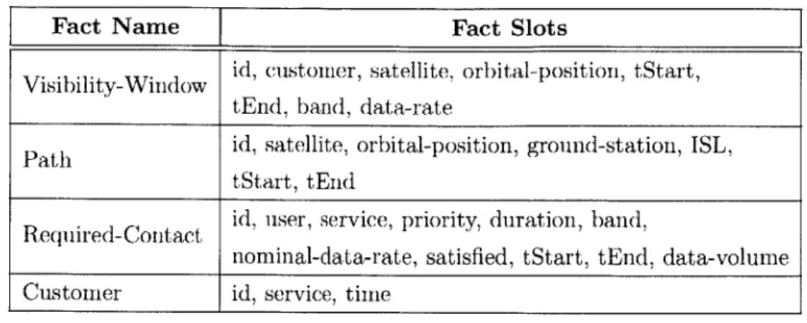
These inputs are run through the core of the model, a rule-based expert system that implements four main parts: A search strategy, i.e. an algorithm that iteratively looks for the optimal subset of architectures with respect to some objective metrics and identifies the best options for each of the architectural decisions. A space and ground segment design algorithm that sizes the different elements of the network (relay satellites, ground stations and their respective antennas). A network evalu-ator that simulates the operations of the system for a typical day of operations by producing a plausible schedule for the different network assets. And finally, a cost estimator module that, given the sized elements, costs the different parts of the space
and ground segment and provides an estimate of the total life cycle cost.
The output of the model is a tradespace of architectures that have been evaluated to obtain both a normalized metric for their benefit and an estimate for their life
38 User Needs
- Timeframe: 2020-2030 - Same number of missions
as today - Same contact time
requirement * Max. data rate = 1Gbps
V 500
450(
400(
xX X xK xArchitectures
-
Pareto Front
0.4
0.5
0.6
0.7
benefit
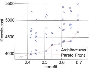
Figure 2-3: Example of a tradespace from SNAT
cycle cost. Figure 2-3 presents an example of the output of the tool in the form of a notional tradespace in the benefit-cost space, and highlights the resulting Pareto front. Each point in the plot represents one particular evaluated architecture, with sized communication payloads, relay satellites and their supporting ground stations.
2.5
Model description
This section presents a detailed description of the SNAT tool and the different mod-ules that compose it. Most of the information herein presented is extracted from references [35] and [34]. Before delving into SNAT's modeling and implementation details, this section presents VASSAR, a methodology for Value Assessment in Sys-tem Architecting using Rules, developed by Selva in reference [44]. SNAT is based on this framework in that it has been implemented using a rule-based expert system. Once VASSAR has been introduced, this section provides a detailed description of the modules used to size the space segment, ground segment, and network capacity. It also provides an overview of the cost module and search engine since both of them have been partially adapted from Selva's previous work.