Publisher’s version / Version de l'éditeur: CIB Publication, 213, pp. 493-509, 1998-04-01
READ THESE TERMS AND CONDITIONS CAREFULLY BEFORE USING THIS WEBSITE.
https://nrc-publications.canada.ca/eng/copyright
Vous avez des questions? Nous pouvons vous aider. Pour communiquer directement avec un auteur, consultez la
première page de la revue dans laquelle son article a été publié afin de trouver ses coordonnées. Si vous n’arrivez pas à les repérer, communiquez avec nous à PublicationsArchive-ArchivesPublications@nrc-cnrc.gc.ca.
Questions? Contact the NRC Publications Archive team at
PublicationsArchive-ArchivesPublications@nrc-cnrc.gc.ca. If you wish to email the authors directly, please see the first page of the publication for their contact information.
NRC Publications Archive
Archives des publications du CNRC
This publication could be one of several versions: author’s original, accepted manuscript or the publisher’s version. / La version de cette publication peut être l’une des suivantes : la version prépublication de l’auteur, la version acceptée du manuscrit ou la version de l’éditeur.
Access and use of this website and the material on it are subject to the Terms and Conditions set forth at
Drying potential of EIFS walls: innovative vapor control strategies
Karagiozis, A. N.; Kumaran, M. K.
https://publications-cnrc.canada.ca/fra/droits
L’accès à ce site Web et l’utilisation de son contenu sont assujettis aux conditions présentées dans le site LISEZ CES CONDITIONS ATTENTIVEMENT AVANT D’UTILISER CE SITE WEB.
NRC Publications Record / Notice d'Archives des publications de CNRC:
https://nrc-publications.canada.ca/eng/view/object/?id=bf75ba79-ad78-4820-b0ca-8a3e36bc1898 https://publications-cnrc.canada.ca/fra/voir/objet/?id=bf75ba79-ad78-4820-b0ca-8a3e36bc1898
http://www.nrc-cnrc.gc.ca/irc
Drying pot e nt ia l of EI FS w a lls: innova t ive va por c ont rol st ra t e gie s
N R C C - 4 1 3 2 6
K a r a g i o z i s , A . N . ; K u m a r a n , M . K .
A p r i l 1 9 9 8
A version of this document is published in / Une version de ce document se trouve dans: CIB Publication, 213, pp. 493-509, April 01, 1998
The material in this document is covered by the provisions of the Copyright Act, by Canadian laws, policies, regulations and international agreements. Such provisions serve to identify the information source and, in specific instances, to prohibit reproduction of materials without written permission. For more information visit http://laws.justice.gc.ca/en/showtdm/cs/C-42
Les renseignements dans ce document sont protégés par la Loi sur le droit d'auteur, par les lois, les politiques et les règlements du Canada et des accords internationaux. Ces dispositions permettent d'identifier la source de l'information et, dans certains cas, d'interdire la copie de documents sans permission écrite. Pour obtenir de plus amples renseignements : http://lois.justice.gc.ca/fr/showtdm/cs/C-42
Achilles Karaglozis
land Kumar Kumaran
2Drying Potential of EIFS Walls: Innovative Vapor Control
Strategies
ABSTRACT:
Durability and service life of EIFS wall assemblies are strongly dependent on the wall's hygrothermal perlorrnance. Hygrothermal performance Is define as the response of the EIFS wall assembly to thermal and moisture loads. Moisture loads available to the structure can originate either from the Interior or the exterior. From the Interior, the Indoor environment provides a contlnuos source of moisture, while from the exterior moisture may be transferred to the wall structure from either the ambient vapor pressure or from wind driven raIn (In liquid form). However, until recently advanced analysis tools/models to provide perlormance knowledge were not available, and even today such models are only available Within the research communities... With the recent large number of EIFS wan failures, moisture engineering through sophistIcated modeling can be applied to assess the drying potentIal of various EIFS walls and test alternative approaches In a fraction of the time and expense as required by field or laboratory testing. The LATENITE model developed at IRCINRCC, a state-of-the-art transient 2-D and 3-D control volume finite difference model, Is employed to numerically solve the heat, air and moisture transport through various EIFS walls. Both vapor and liquid transport through each material layer are considered strongly coupled to the material properties, I.e. the sorption curves, liqUid diffuslvlty and vapor permeablllty. Latent heat generated due to moisture transport and natural convection induced moisture flow In each material layer are fully accounted for.
In this paper the authors, present a study to determine the drying potential of EIFS systems by employing the LATENITE model. The hygrothermal perlormance of these EIFS systems were investigated for one climatic location. The effect of three vapor control strategies were investigated for the climatic locatIon of Wilmington, NC. Case 1 EIFS wall did not Include a vapor retarder, Case 2 wall employed an Innovative-'ntelllgent rstardel'and Case 3 Included a
lResearch Officer, National Research Council Canada, Institute for Research in Construction, Building Performance Laboratory. Ottawa, Canada
2Senior Research Officer. National Research Council
Canada.
Institute for Research in Construction, Building Performance Laboratory. Ottawa, Canada6-mll polyethylene retarder. The long-term perlormance of these EIFS walls Installed with these different vapor control strategies was simulated for a period of two years. The Influence of wind-driven rain, solar radiatron and air movement within the cavity were Included In the analysis on a . houriy basis, Results from this Investigation showed the Importance of the vapor control strategy on the long-tenn hygrothermal perlonnance of the EIFS wall.
KEYWORDS: Exterior Insulation Finish Systems, Vapor Control, Drying Potential. Moisture Transport, Sorption. Water Vapor Permeance, Moisture Diffusivity
INTRODUCTION
Exterior insulation finish wall systems have become one of the most popular exterior building envelope systems in the residential and commercial construction market in North America. Essentially these wall systems are based on faced sealed principle and consist of an exterior reinforced synthetic plaster base and finish coat. a plastic foam insulation. a sheathing board usually oriented strand board (OSB) or plywood. an insulation cavity, a vapor retarder, and finally an interior gypsum board. The advantage of these wall systems is that they are aesthetically pleasing, energy efficient. lightweight. and low construction cost wall cladding system.. Market potential for these systems is very favourable, especially in the energy retrofit applications as well as new constructions.
EIFS walls were originally developed in northern Europe where they have successfully been performing for the past 30 years. The methods, materials and sheathing systems employed in Europe are however somewhat different from those employed in North America. This attributes to the differences found in the durability and performances of these walls.
Recently. Nisson [1995] presented a summary of the serious moisture problems in EIFS construction in the New Hanover County area (North Carolina). Moisture problems ranging from high moisture contents in the exterior sheathing . to total rotting were uncovered. Apparently all of the 3200 EIFS homes needed
some remedial repair. Since then. various studies and investigations by
consultants and research organizations [Brown et aI, 1996]. [Crandell and Kenny, 1995], as well as EIFS manufactures such as USG have shed light on the causes of these failures. Most of the catastrophic failures have been traced to flashing details and the penetration of water into the wall systems [Nelson and Waltz, 1996]. However, while water entry should be avoided for any building envelope system. an often overlooked fact is that these walls systems did not provide a route for the escape of ingressed moisture therefore the drying of the enclosure. A general conclusion drawn, but not unanimously agreed upon among the EIFS manufactures, has been the condemnation of face sealed wall
approach however, is unfair to all the standard face seal EIFS constructions that have performed satisfactory in the past.
To date (August, 1997) knowledge on the hygrothermal performance of EIFS walls that includes all climatic effects such as rain water, solar radiation, night sky radiation as well as the influence of wind-speed and site/wall orientation on both the convective and mass transfer coefficients Is not available. This results in the misinterpretation of some of the hygrothermal processes that occur in these wall systems. Wrong interpretation, then limits the application of innovation strategies (materials with memory capabilities, or material layers with
strong functional dependencies on transmission coefficients) that could
potentially enhance the durability performances of the wall systems
In this paper, the authors present a study to determine the drying potential of an EIFS system by employing modeling. The source of water is considered due to the initial construction moisture in the sheathing board. The study will attempt to address some of the issues present in vapor control strategies using the state-of-the-art hygrothermal model LATENITE. The moisture performance of the EIFS system was investigated for the climatic conditions of Wilmington NC. Three vapor control strategies: a wall that did not incorporate a vapor retarder (no-retarder), a wall that employed an innovative Iiintelligent retarder (intelligent
retarderl ) and for a wall that incorporated a 6-mil polyethylene retarder (6-mil
Poly) were investigated.
OBJECTIVES OF PRESENT STUDY
The present work Is concerned with the hygrothermal performance (drying potential) of a typical EIFS wall structure SUbjected to three selected vapor diffusion control strategies. The objective of the work was to determine the long-term hygrothermal performance of the wall structure for each of the strategies while subjecting the exterior boundary to real weather data (including temperature, vapor pressure, wind speed and orientation, solar radiation, sky radiation, cloud indexes and rain) by employing a moisture engineering approach that blends, intensive numerical analysis and accurately defined
material property measurements. The weather、セャエ。 used are representative of a
mixed-climate found in the east coast of United States (NC).
1'Intelligent Retarder (or Smart Retarder) is dermed as a retarder that permits high water vapor diffusion' at high relative humidities.(Kunzel,l996)
VAPOR CONTROL THEORY
Unintentional water entry into wall constructions can lead to destructive consequences [Hutcheon, 1963]. Moisture entry into the wall structure can be caused mainly by four processes: vapor diffusion, liquid diffusion, water leakage and moist air leaking inward or outward (being more Important for cold climates) through the building envelope. The present stUdy Is concerned with moisture transport due to vapor and liquid diffusion throughout the wall, and convection only within the insulation cavity. Moisture transport by diffusion occurs under the influence of a vapor pressure or moisture content (capillary suction pressure) gradient acting across the wall structure. The rate of moisture flow is dependent upon the magnitude of the vapor pressure gradient and the vapor permeances as well as suction pressure and hydraulic conductivity of the component layers of the wall assembly. Additional factors of significant importance are the overall integrity of the bUilding material (i.e. cracks and openings), the interface contact and surface moisture resistances. In general, for a given permeable structure the greater the vapor pressure difference across a wall assembly, the greater will be the rate of diffusion. The moisture movement is almost always outward of the building envelope during winter (heating season) and can be inward or outward during the summer (cooling season). With the current construction practices, houses are better insulated and more airtight, resulting in colder and warmer
regions within the wall structure and higher Indoor relative humidities. If the
vapor pressure and temperature are respectively high and low enough in a material layer, then a thermodynamic change of state occurs and vapor changes into the liqUid state(water) or even into solid state(ice). The condensation within the concealed wall structure can thus be a highly localized effect.
To control this moisture flow into the wall structure, vapor barriers have been devised. Vapor barriers are materials or systems which adequately retard the transmission of water vapor across the wall assembly, offering a high resistance to the diffusion of water vapor. Indeed in the National Building Code of Canada (NBC) code requires that "a vapour barrier protection shall be Installed on the warm side of the insulatlon"[NBC, 1995]. The need is critical where insulation systems operate below freezing conditions. This requirement was stipulated In the 1940's due to the noticeable damages attributed to high moisture levels in the walls.
Due to the higher indoor relative humidities, especially with the use of humidifiers for increased levels of human comfort, vapor barriers are incorporated near the warm side (Interior) of the wall structure (cold climates ONLY). It Is generally advocated as a safe design principle since the entry of moisture is restricted closer to the source, which is normally the higher vapor pressure side. This is generally true for climates that are designated as cold. .The application, location and selection of the vapor retarders is. dependent .on wall design and climatic conclitions. However, only a limited number of studieS
1976; Latta, 1976; Hutcheon, 1963; Burch and Thomas, 1992]. Indeed all studies only considered one dimensional heat and moisture flows and most of these studies, with the exception of the latest, drew conclusions based on the use of the steady state 1-0 Glaser method [Glaser, 1959] or its simple
extensions [Trethowen, 1979]. The most definitive and conclusive study
[Nisson, 1994] on the use of vapor control strategies for cold climates has been the work of [Karagiozis and Kumaran ,1993]. This previous study by the authors is the first study that evaluated vapor control strategies for wood frame construction wall systems in 2-0 for cold climatic conditions. Results showed that for weather conditions such as Vancouver, the need for a 6-mil polyethylene layer may not be needed, instead a coating of paint with a permeance of even 400 nglPa m" s may prevent harmful moisture accumulation due to diffusion. In this study, the drying potential of an EIFS wall is investigated with respect to the choice of three types of vapor control strategies. The work presented in the this study is more advanced than the previous study [Karagiozis and Kumaran 1993], as liquid movement is included, and real weather conditions including solar radiation, sky radiation, wind-driven rain and cloud indexes are accounted for in the investigation.
MATERIAL PROPERTY DETERMINATION
Hygrothermal material properties for some of the materials of the EIFS wall system were measured at the National Research Council of Canada, Thermal Insulation Laboratory, The water vapor permeance of the intelligent
vapor retarder or otherwise named as a Smart Retarder was measured at
Institute fur Bauphysics by [Kunzel, 1996]. Water Vapor Permeance
The water vapor transmission characteristics of EIFS panel or lamina (includes finish and basecoat systems), extruded polystyrene (EPS), oriented strand board, and pine wood [Kumaran et ai, 1989] were determined according to the modified ASTM E 96 Test Method for Water Vapor Transmission of Materials [Lakey et ai, 1997]. Four different sets of relative humidities were used as boundary conditions in order to determine the dependence of vapor
transmiSSion characteristics as a function of relative humidity. Table 1 gives results on the vapor permeances of the tested materials.
TABLE 1-Vapor transfer properties.
Panel .EPS Coating
Sample Average
RH.%
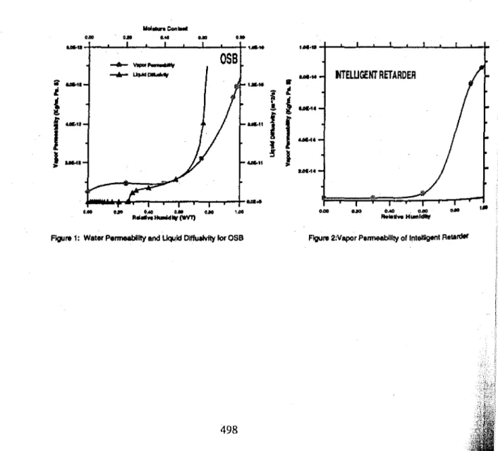
16 27 77 91 Vapor Permeance. kg/s·m2 ·Pa 1.1E-10 1.5E-10 1.1E-10 1.5E-10 1.2E-10 1.6E-10 1.7E-10 2.2E-10 3.3E-10 4.1E-10 5.1E-10 7.6E-10The vapor permeability and liquid diffusivity of the
ass
layers as a function ofrelative humidity and moisture content respectively Is presented in Figure 1.. The vapor permeability of the Intelligent vapor retarder is a strong function of
relative humidity as shown in Figure 2 [Kunzel, 1996]. This vapor retarder
selectively allows higher vapor transmission by diffusion at high relative humidities. The vapor diffusion through the intelligent retarder Is inhibited until
relative humidities of apprOXimately 70
%
are present. This allows a greatwindow of opportunity to employ selective moisture transport only at higher relative humidities. ... Con_ 0"'" 0.10 tAO UO 0.10
...
.-
.M·ta -+- BMセOSS
... ijipiセ"·M
tfl'ELUGENT RETARDER..
_.
,"'to..
lI
tot
ll.Oll...
4 l!. . . . .11f
f ...
f _.
J
I! ...
!I
セオ • .01...4_
..
G.OO UII OM a. a. 1.00 abO Uli (lAD . 0.00 0.10
.-RUII.. lI_11W(WV1) _lI..
H_'_
figure 1: Watel' PelJM8blHty and liquid DIffuaMty for OSB FIgure 2:Vapor P81T1leablHty of lnlelllgenl Relardel'
DESCRIPTION OF THE MODEL
A detailed model description of the LATENITE version 1.0 hygrothermal model is given by [Hens and Janssens, 1993] , [Karagiozis ,1993], version 1.2 by [Salonvaara and Karagiozis, 1994J, and version 1.3 [Karagiozis. 1997]. A brief overview of the model is presented here. The moisture transport potentials used in the model are moisture content and vapor pressure; for energy transport, temperature is used. The equations are developed on a Cartesian rectangular co-ordinate system. contain explicit and implicit time discretizations. and are spatially discretized using the control volume formulation. Approximate factorization and full solution procedures are incorporated into the model to solve the differential equation In delta form.
The
LA
TENITE model has been recently upgraded to include the porous air flow through Insulation and cracks by solving a subset of the Navier Stokes equations: Darcy's equations. In addition, the solution domain has beenextended to 3·dimensions, allowing real practical problems to be solved. The model includes the capability for handling internal heat and moisture sources. gravity driven liquid moisture, and sUrface drainage capabilities. An important feature of the upgraded LATENITE model is its extension from prOViding
deterministic solutions to stochastic-statistically based ones. LATENITE employs non-linear hygrothermal properties as found in nature. The porous media
transport of moisture (vapor and liquid) through each material layer is
considered strongly coupled to the material properties (i.e., the sorption-suction curves). The corresponding moisture fluxes are decomposed for each phase and are treated separately. The moisture transfer equation. including liquid and vapor transfer, is
where
(1)
=
mass flux, kg/m2.s
=
drydensity of porous material, kg/rn3=
liquid moisture diffusivity, m2/s=
moisture content, kgjk9d=
temperature, °C=
vapor permeability, kg/s·m·PaPv
=
vapor pressure, Pa v.=
velocity of air. m/sPv
=
density of vapor in the air, kg/m3 K=
moisture permeability, sP.
=
density of liquid water. ォァOュセ 9=
acceleration of free fall, m/s2•Wind driven rain is modelled as a source term on the exterior wall surface. However. the amount of water that can penetrate Into the porous material is limited by the maximum allowable moisture content in the exterior material.
PROBLEM DESCRIPTION
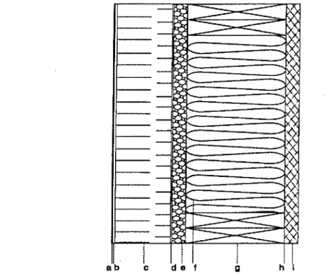
The hygrothermal performance (drying potential) of an EIFS wall depicted in Figure 1 was analyzed with three interior vapor control strategies. The measured water vapor permeabillties and liquid diffusivities for EIFS panel, and oriented strand board, were employed in the simulations (Table 1). Material properties for all other layers were employed from the LATENITE property database [Karagiozis et ai, 1995).
A perfectly faced sealed solid EIFS wall system (no-window details) was selected for the numerical analysis. The wall is centrally located in the middle of a 2-storey building and Is composed of the following layers starting from the exterior to interior: a 5mm lamina, a 50 mm extruded polystyrene board, a 1 mm adhesive coating, a 12.5 mm oriented strand board, 89 mm of fiber glass insulation, 76 mm thick double bottom and top plate, the vapor control layer, and 12.5 mm gypsum board. The inside surface of the gypsum board was coated· with a vapor open paint (permeance approximately 200 ng/m'sPa or 4 perms).
The oriented strand board moisture content was assumed at 44
%
initially.This represents a very wet initial moisture condition in the OSS layer. All other
layers In the wall system were assumed to be in equilibrium at 80 % relative
humidity.
Wind driven rain water was included in the analysis, the exterior surface was exposed to the amount of rain that typically hits a vertical wall. This amount depends on the intensity of precipitation, wind speed and wind direction as well as the location on the wall surface. Wind driven rain was used in the analysis as calculated by employing a commercially developed model [ASe, 1995). An equation for wind-driven rain used in the hygrothermal model was created and was based on a numerical stUdy [Karagiozis and Hadjisophocleous, 1995) that presents the results generated by the wind-driven rain droplet simulations.
The wall was exposed to outside air temperature and the relative humidity that varied according to the weather data from the selected location (Wilmington). The simulations were carried out for a one and half year exposure starting on the 1st of October. The solar radiation and long wave radiation from the outer surfaces of the wall were included in the analysis. In this study, no air infiltrating or exfiltrating was considered; therefore the primary mode of water transmission is due to diffusion processes, both vapor and liquid transport. The LATENITE 1.3 hygrothermal model was employed, and the deterministic method was invoked for all simulations.
h I g c de f
-
--
>C tA:--
-セ
-
-----
--
X 7-セ-
\
-
), tA<;:
セ_
... Li: セ - セ ):'(-
'i, ::::z,r b-"'-::h' h-"( セ--
-
,)<-
--W'--
--
--I
I
abFIG. 3-The analyzed wan structure In detail: (a+b)5mm base. and finish coating, (c) a 50
mm extruded polystyrene board, (d) a 1 mm glue layer, (e) a 12.5 mm oriented strand board,(f) 89 mm of fiber glass Insulation, (g) 76 mm thick double bottom and top plate, (h) the vapor control layer, and (I) 12.5 mm gypsum board
BOUNDARY CONDITIONS
Internal conditions were kept constant at a temperature21°C and relative
humidity 45
%
RH (Pv=
1119Pa) throughout the year. The US National ClimaticWeather Center [1995] data for the years 1961·1962 were used in the
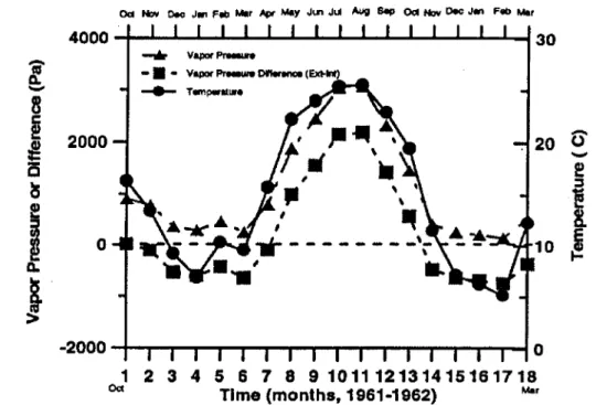
simulations. The monthly average temperatures and vapor pressures and vapor pressure differences (Pllxterior - Plnterlor) for Wilmington, are shown in Figure 4. The
1961 yearly average temperature and vapor pressure in Wilmington is 16.5
°e,
and 1378 Pa, respectively.
The modeled wall on the 2th floor of the building was facing south. i.e. and the azimuth angle of the wall was 180 degrees. The heat transfer coefficients for
external and internal surfaces were kept constant at 20 and 10 W/m2
K, respectively. The mass transfer coefficients for the exterior were assigned values that varied from hour to hour depending on the exterior weather wind speed and orientation conditions.
4000
-+...
-L....I.-..&-...セ ..._ _-..L...L...-I--'-...30 2000 o . . . カ セ _ _ - • • カセ セ on.r.nc.(Exl-lnI) -e- T_p.tMllte .206
-
!t
10セ
·2000 0 1 2 3 4 5 6 7 8 9 101112131415161718oa Time (months.1961-1962) Mar
FIG 4.-The monthly average temperatures. vapor pressures and vapor
pressure difference (exterior-interior) for Wilmington weather conditions.
SIMULATION RESULTS
In Figure 5, the total amount of moisture present in the wall system as a function of time is presented to show the relative hygrothermal performance of the EIFS wall for the three different vapor control strategies. The simulations start from the first day of October (1961) for a period of one and half years. The wall without a vapor retarder dried out the fastest. followed by the wall with the intelligent retarder. The slowest drying is exhibitted by the wall that included the 6-mil polyethylene vapor retarder. From this figure. it becomes apparent that the preferred drying of this wall system in Wilmington is primarily towards the interior. Indeed, for higher inside relative humidity. the drying potential of the overall wall system will be substantially reduced.
Figure 6. depicts the transient moisture content of the glass fiber insulation layer. Here it is evident that as the interior vapor control becomes tighter. the amount of seasonal moisture accumulation in the insulation cavity increases. The intelligent retarder performs in a beneficial manner by allowing moisture to pass through the retarder when relative humidities at the
insulation-gypsum board interface increase. In the case without a retarder, no seasonal
moisture accumulation is observed in the glass fiber insulation.
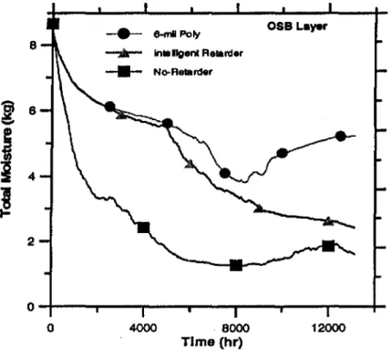
Figure 7 shows the transient total moisture in the orientated strand board sheathing layer. This layer is one of the most critical layers in terms of durability
and potential for mould growth. Rapid drying is observed for the no-retarder
case, followed by the intelligent retarder and the slowest drying in the 6-mil polyethylene case. Indeed, after approximately 8000 hr (August), the case with the 6-mil polyethylene begins to accumulate moisture due to seasonal effects. A similar effect is also observed for the no-retarder case. Continuous drying is observed only for the intelligent retarder case.
In Figure 8 the total moisture contents in the top and bottom wood plates are shown as a function of time. It is evident that moisture is initially building up in the cases other than the no-retarder one. The initial relative humidity assigned to the plates corresponded to 80
%
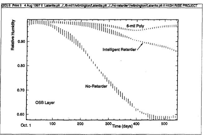
RH and for both the intelligent retarder and the 6-mil polyethylene cases moisture accumulated in these layers. Drying however, did occur later in the year for both cases.In Figure 9. spatial and temporal relative humidities are shown for the three vapor control strategies in the aS8 layer. The results show the relative humidities in the upper most region of the ass (2 mm from the top). This height was chosen as being· the location for the highest moisture contents (lowest drying potential). For this region of the 058, 200 days are required to dry from 99 %to 80 %relative humidity to limit the possibility for degradation processes. Similarly, Figure 10 shows the relative distributions for the
osa
region at 1.2 m from the bottom of the wall system. It is observed that lower relative humidities are found in this region in the no-retarder case.CONCLUSIONS
Vapor diffusion control strategies have a significant effect on the hygrothermal performance (drying potential) of EIFS walls for mixed climatic conditions. This study, which included the effects of vapor transport, liqUid transport and natural convection effects, found that the use of a polyethylene vapor retarder( type I or type II) may not be beneficial to drying the initial construction moisture. The results showed slow drying even for the no-retarder case as the drying potential for climatic conditions of Wilmington are not very favourable.
While all results from this study point towards the elimination of the vapor retarder in this particular EIFS wall, the intelligent retarder is recommended instead. The intelligent retarder can provide a drying mechanism for the wall as long as the interior relative humidity Is maintained below 70
%.
If buildings are equipped with air conditioning equipment, moisture transport from the interior can be regulated. Additional research is needed to determine the critical range of interior climatic conditions that owners of the building must adhere to. The intelligent retarder permits a wide window of opportunity for moisture engineering innovations, especially when the designer can not guarantee perfect control of moisture entry into the cavity. Walls, must be designed to accommodate some form of synchronised moisture control that utilizes drying towards the interior as well as the exterior. EIFS walls that incorporate such innovations as the intelligent retarder can be developed with substantially highermoisture load tolerances for any climatic region, without necessarily requiring special cavities or other expensive changes in design.
Today, by effectively employing advanced moisture engineering analysis, integrating material properties, system and sub-system performances (lab and field stUdies) and modeling building envelope systems can be optimally designed. Advanced hygrothermal modeling is an efficient means to develop engineered construction products, similar to other high-tech industries such as aerodynamics, automotive and even the electronic fields.
The results provided in this paper are only applicable to the specific materials, wall specifications and weather conditions employed. Further work is needed to characterize the effects of defects in the exterior surface or possible moisture infiltration or exfiltration from the interior or exterior environments.
ACKNOWLEDGEMENTS
The authors of this stUdy would like to thank Mr. John Lackey, technical officer at NRC, for his assistance in the measurements and sample preparation.
REFERENCES
ASTM Standard Designation C 755 - 73. 1976. Standard Recommended
Practice for Selection of Vapor Barriers for Thermal Insulations, 1976 Annual Book of ASTM Standards, pp. 527-543.
Lakey J.C., Marchand R.G. and Kumaran, MK A Logical Extension of
the ASTM STANDARD E96 to Determine the Dependence of Water Vapor Transmission on Relative Humidity, ASTM STP 1320, pp. 456-468.
Bomberg, M., J. Lstiburek and Nabhan F. 1997. Performance Evaluation
of Exterior Insulation and Finish Systems (ElFS), Seventh Conference on Building and Science and Technology, March 20-21, pp.1-15.
Brown, W., Ullett, J. Karagiozis A. and Tonyan T. 1997. Barrier EIFS Clad
Walls: Results from a Moisture Engineering Study, J. Thermal Insul. and Bldg. Envs., Vol. 20, Jan., pp. 1-21.
Crandell. J.C. and T. Kenny 1995. Investigation of Moisture Damage in
Single-Family Detached Houses Sided with Exterior Insulation Finnish Systems in Wilmington NC, NAHB Research Center, Inc. August
Nelson, P. and Waltz M. 1996. EIFS - Surface Sealed Wall Systems that
Need Flashings, Exterior Insulation Finish Systems (EiFS): Materials, Properties, and Performance, ASTM STP 1269, pp. 149-164.
i
fl
I
!
,
Kudder J. R. and Lies K.M. 1996 Comparison of Class PB EIFS Lamina
Water Transmission Test Methods, Exterior Insulation Finish Systems (EIFS): Materials, Properties, and Performance, ASTM STP 1269, pp. 84-102.
Nisson, N. J.D. 1995. Severe Rotting Found in Homes with Exterior Insulation Systems", Enery Design Update, Vol. 15, No. 12, Dec, pp.1-3. Nisson, N. J.D. 1994. Ordinary Paint as Replacement for Poly Vapor Retarder", Enery Design Update, May, pp.5-7.
Burch, D.M. and Thomas, W.C. 1991. An Analysis of Moisture
Accumulation in a Wood Frame Wall SUbject to Winter Climate, National Institute of Standards and Technology Report NISTIR 4674.
Karagiozis, A.N. and Kumaran, MK 1993. Computer Model Calculation on the Performance of Vapor Barriers in Canadian Residential Buildings, ASHRAE Transactions, Vol. 99(2), pp. 991-1003.
Kumaran, M.K., Mitalas G.P., Kohonen, R. and Ojanen T. 1989. Moisture
Transport Coefficient of Pine from Gamma Ray Absorption
Measurements, ASME HTD, Vol.123 pp. 179-183
Glaser, H. 1959. Graphisches vefrhren zur untersuchung von
diffusionsvorgangen. Kaltetechnik, heft 10, 345-349.
Kunzel, H.M. 1996, Humidity controlled vapor retarders reduce risk of moisture damage, Proceedings of the 4th Symposium, Building Physics in the Nordic Countries, Espoo, Finland, Sept. 9-10, pp.447-454.
Hutcheon, N.B. 1963. Humidified Buildings Canadian Building Digest, UDC 697.93, Division of Building Research, National Research Council Canada.
Latta, J.K. 1976. Vapor Barriers: What are they? Are they Effective? Canadian Building Digest, UCD 699.82, Division of Building Research, National Research Council Canada.
National Building Code of Canada. 1990. Location of vapour barriers, 9.25.6.2. p 292.
National Building Code of Canada, Supplement No.1, 1977. Climatic Information for Building Design in Canada, National Research Council of Canada.
Quirouette, R.L. 1985. The Difference Between a Vapor Barrier and an
Air Barrier. Building Practice Note BPN54 Division of Building Research,
National Resea rch Council Canada
Rousseau, M.Z. 1983. Control of Surface and Concealed Condensation.
Humidity Condensation and Ventilation in Houses Building Science Insight, National Research Council Canada, pp. 2940.
Trethowen, H. A 1979. The Keiper method for moisture design in buildings.
Building Research Association of New Zealand,
p.
9.Karagiozis, A and Hadjisophocleous G. 'Wind-Driven Rain on High-Rise
Buildings", Thermal Performance of Exterior Envelopes of BUildings VI,
Clearwater Beach, Florida, 4-8 Dec. 1995.
Karagiozis, A., Salonvaara, M. and Kumaran,
K.,
"LATENITE HygrothermalMaterial Property Database, lEA Annex 24 Report T1-CA-94/04, Trondheim,
Norway, 1994.
Hens, H. and Janssens
A,
"Inquiry on HAMCAT CODES", International EnergyAgency, Heat, Air and Moisture Transfer in Insulated Envelope Parts, Report Annex 24, Task 1, Modeling, 1993.
Karagiozis, A, "Overview of the 2-D Hygrothermal Heat-Moisture Transport
Model LATENITE", InternallRC/BPL Report, 1993
Salonvaara M. and Karagiozis A, "Moisture Transport in Building Envelopes
using an approximate Factorization Solution Method", CFD Society of Canada, Toronto, June 1-3 1994.
Karagiozis At 1997 Porous Media Transport in Building Systems», CFD Society
of Canada, Victoria, May 25-27, 7-21 to 7-25
ASe (1993) Theory Documentation for TASCflow, Version 2.2, Advanced Scientific Computing Ltd., Waterloo, Canada.
AESC.(Atmospheric Environment Service of Canada). National Climatic Center, 1995, Data for Wilmington N.C.
Environment Canada, Canadian Climate Normals. Vol. 3, Atmospheric Environment Service, Downsview, Ontario, 1983.
10
---
6-m11Polyi
-.-
intelligent Retarde-
---j
8 No.J\eIB Ide rJ
6 4 2 - + - -...---r--_-_---.---,r---_+_
FIG. 5: Total Drying Potential of the Three Vapor Control Strategies 5-+--...- ...
--.a.---...- ...
- - o o t _o 4000 eooo
Time (hr)
12000
FIG. 6: Moisture Performance ofthe Insulation Layer
12000 Gla.. Fiber Layer
4000 8000 Time (hr) セ 6·ml'Poly - , k - Intailigent Retarder ____ No-Retarder o 4 2 3
· v
---
8-mIIPoly OSB Layer8
--.-1n.lIlgent Relarder -II- No-Ralarderセ
8i
i
4!
2 0-+--..._-_--__--...---..--_---11-o 4000 . 8000 Time (hr) 12000FIO. 7: Moisture Performance of the OSB Layer
1.2
l
5
oi
i 0.8セ
Intellgen!RetarderWood PIn.. (Top+Bottom)
0.4 セMMッイ⦅M⦅MM⦅M⦅セMNNNLNNMMイ⦅⦅M⦅ゥ⦅ 12000 o 508 4000 8000 Time (hr)
'1IIIl1l1lll:r;'I'I'IIIIJIIIII'IIIIIIIIIIIII"1111I
XMュャャセoiケ
"",,,"'1111'III
lilil
'",,,,,,,,,,
II "
II
lilli" , ,,. IIIi
BセGGGGGG !1 1 111'I
Intelligent Reterder I , , , , " I, ",
'I II No-Retarder II
III III III OSBLayer I, nt 4 セ セOJ :c Nセ 0.90 til &! 0.80 0.70 0.60 en e. . . , m.
..
, entte. t I H I' , I , ,111111111111 . "Oct.1 100 200 300Time (days)400 500
FIG. 9: Transient and Spatial Relative Humidity Distribution in the OSB :Layer (TOP 2.40 m)
nt 1997 enteo It. . 1 lmr 0 tenteo .. m enlte.1t IH r PA E
o.a
I-".... ,... 'II'll
liiii
l
f
セ 0.9j
0.7 0.6 I-0.5 0.4 Oct.1 OSBLayer 100I'
III " IIII II " , ," , .... 1 1111'1i1" 6-mliPolyI
III
11 '111' I' , "/
III"""
Intelligent Retarder ' I ,I
II
I
II
No-Retarder . II III
I
, 200 300Tims (days)4OO 500FIG. 10: Transient and Spatial Relative Humidity Distribution in the OSB :Layer (MIDDLE 1.2