Publisher’s version / Version de l'éditeur:
Vous avez des questions? Nous pouvons vous aider. Pour communiquer directement avec un auteur, consultez la première page de la revue dans laquelle son article a été publié afin de trouver ses coordonnées. Si vous n’arrivez pas à les repérer, communiquez avec nous à PublicationsArchive-ArchivesPublications@nrc-cnrc.gc.ca.
Questions? Contact the NRC Publications Archive team at
PublicationsArchive-ArchivesPublications@nrc-cnrc.gc.ca. If you wish to email the authors directly, please see the first page of the publication for their contact information.
https://publications-cnrc.canada.ca/fra/droits
L’accès à ce site Web et l’utilisation de son contenu sont assujettis aux conditions présentées dans le site LISEZ CES CONDITIONS ATTENTIVEMENT AVANT D’UTILISER CE SITE WEB.
Research Report (National Research Council of Canada. Institute for Research in
Construction), 2002-09-01
READ THESE TERMS AND CONDITIONS CAREFULLY BEFORE USING THIS WEBSITE. https://nrc-publications.canada.ca/eng/copyright
NRC Publications Archive Record / Notice des Archives des publications du CNRC :
https://nrc-publications.canada.ca/eng/view/object/?id=8b2b2477-d5c6-4712-bb30-11403a35223a https://publications-cnrc.canada.ca/fra/voir/objet/?id=8b2b2477-d5c6-4712-bb30-11403a35223a
NRC Publications Archive
Archives des publications du CNRC
For the publisher’s version, please access the DOI link below./ Pour consulter la version de l’éditeur, utilisez le lien DOI ci-dessous.
https://doi.org/10.4224/20378836
Access and use of this website and the material on it are subject to the Terms and Conditions set forth at
Kemano Fire Studies - Part 2: Response of a Residential Sprinkler
System
Kemano Fire studies – Part 2: Response of a Residential Sprinkler
System
Crampton, G.P.; Carpenter, D.W.;
McCartney, C.; Leroux, P.
IRC-RR-109
September 2002
http://irc.nrc-cnrc.gc.ca/ircpubsKEMANO FIRE STUDIES – Part 2: Response of A Residential Sprinkler System
By
Joseph Z. Su, George P. Crampton, Don W. Carpenter, Cameron McCartney, Patrice Leroux
ABSTRACT
NRC’s Fire Risk Management Program has completed an experimental study of a residential sprinkler system, using the unique opportunity of the Kemano Public Safety Initiative. A series of full-scale fire suppression experiments were conducted in Kemano, a deserted town in northern British Columbia.
A wood-framed bi-level house (900 square feet per floor, 1800 square feet total) was used for the evaluation of a cross-linked-polyethylene (PEX-a) pipe sprinkler system. A
residential sprinkler system with 11 quick response sprinkler heads (temperature rating of 68.3°C or 155°F) was designed and installed (in accordance with NFPA 13D) in a basement recreation room and throughout the main floor. The system was designed to prevent flashover in the room where fire originated and to allow response time for the fire department.
The sprinkler system was tested four times for two fires originating in a basement recreation room, and one time each for the ground floor bedroom and the living room. Smoke detectors, carbon monoxide detectors and heat detectors were installed in the experimental house. The observations made included temperatures in the fire room and egress route, CO and CO2 concentrations, activation times of sprinklers and smoke, heat and CO detectors, and video records of smoke movement.
In the recreation room, the plastic pipes and fittings were installed on open wood joists. The system was exposed to temperatures as high as 140°C in two experiments. After exposure to temperatures above their rated temperature of 93°C (200°F) at 552 kPa (80 psi) for 140 seconds, the pipes and fittings were not visibly damaged, and the sprinkler system was successfully actuated and controlled the fire.
In all four recreation room experiments, a single sprinkler head controlled and contained the fire within 1 minute of the sprinkler activation. The sprinkler water spray cooled down the fire compartment and limited the damage to the furniture near the ignition source. The walls, open wood joists or ceiling of the fire rooms had soot deposition but no major damage. For those experiments done with the fire room door closed, the fire did not affect temperature or visibility along the egress route.
The effectiveness of heat and smoke detectors was also investigated in the sprinkler experiments. As expected, the heat detectors, which were rated at 57°C (135°F) and a temperature rise of 8.4°C/min (15°F/min), were always actuated earlier than the sprinkler. Smoke detectors installed on the egress route were actuated before the sprinkler when the fire room was open to the egress route but after the sprinkler when the fire room door was closed.
The Kemano townsite has provided an excellent opportunity for full-scale fire testing. The valuable information obtained from the testing of detection systems and polyethylene pipe sprinkler systems will contribute to enhanced fire safety and provide a firm basis for further research
.
TABLE OF CONTENTS
1.0 INTRODUCTION ...1
2.0 EXPERIMENTAL HOUSE AND SPRINKLER SYSTEM ...1
3.0 FIRE EXPERIMENTS...3
3.1 Test 1...3
3.1.1 Experimental Set-up of Test 1 ...3
3.1.2 Experimental Results of Test 1 ...4
3.2 Test 2...6
3.2.1 Experimental Set-up of Test 2 ...6
3.2.2 Experimental Results of Test 2 ...6
3.3 Test 3...7
3.3.1 Experimental Set-up of Test 3 ...7
3.3.2 Experimental Results of Test 3 ...8
3.4 Test 4...9
3.4.1 Experimental Set-up of Test 4 ...9
3.4.2 Experimental Results of Test 4 ...10
3.5 Comparison of Temperatures at Various locations...11
4.0 CONCLUSIONS ...12
5.0 ACKNOWLEDGEMENTS ...12
6.0 REFERENCES ...13
LIST OF TABLES Table 1 Calculated Flow at Various Manifold Pressures...2
Table 2 Results of Flow Verification Tests...2
Table 3 Experiment Matrix ...3
Table 4 Results of Test 1 (Basement Recreation Room, May 15, 2001) ...5
Table 5 Results of Test 2 (Basement Recreation Room, May 16, 2001) ...7
Table 6 Results of Test 3 (1st Floor Bedroom #1, May 16, 2001)...9
LIST OF FIGURES
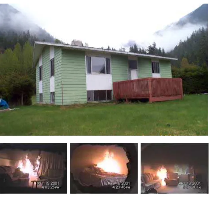
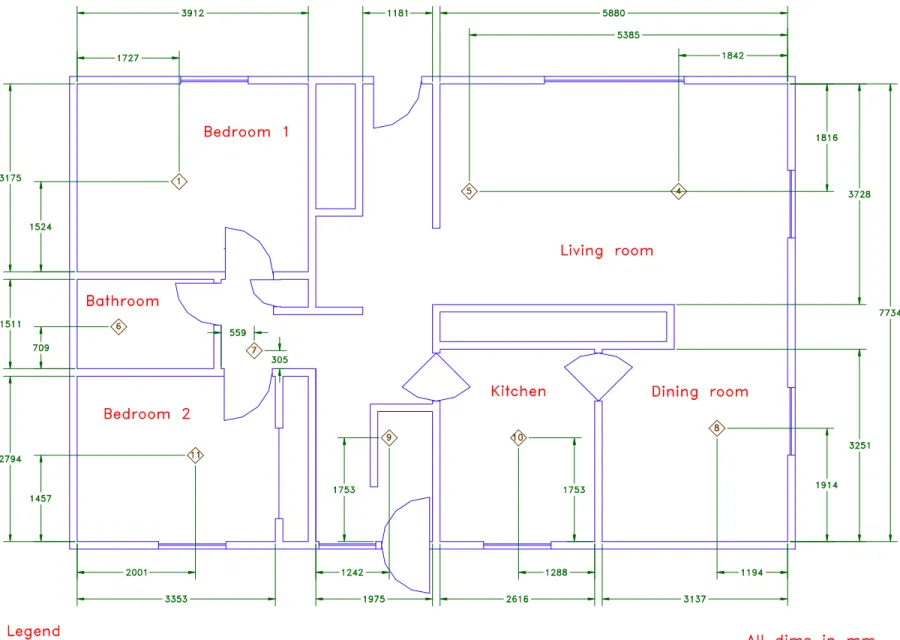
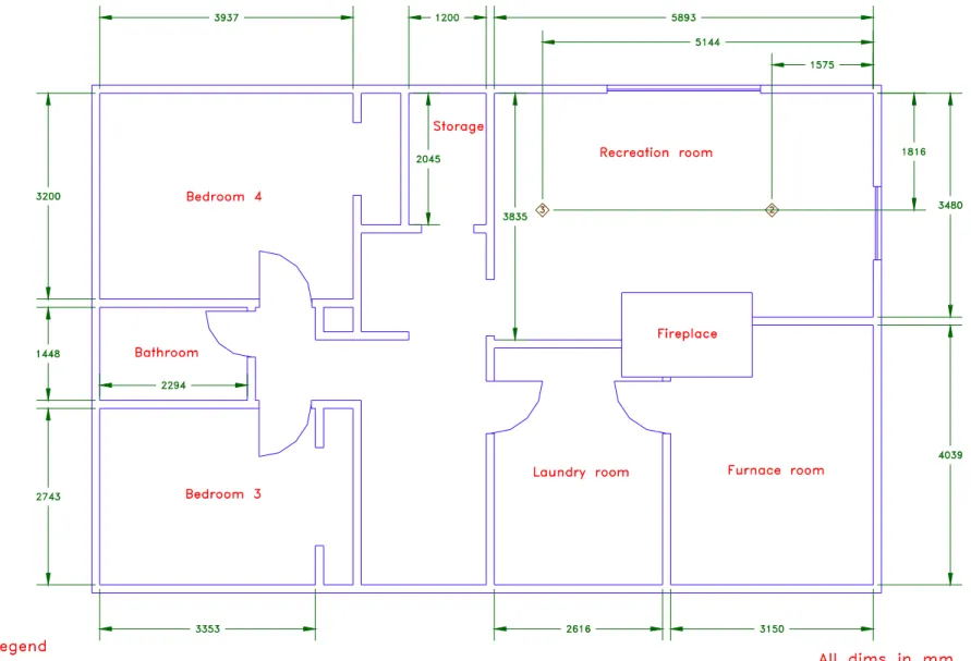
Figure 1 Family dwelling for experiments Figure 2 Floor plan of the experimental house
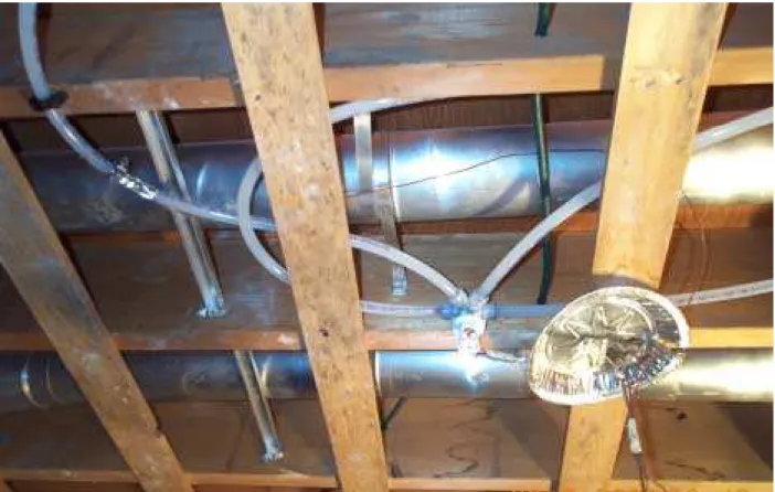
Figure 3 Recreation room ceiling torn down to expose wood joists Figure 4 Sprinkler water supply and system manifold
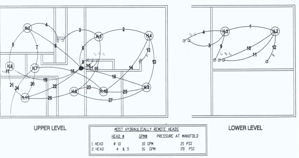
Figure 5 Schematic drawing of the sprinkler system
Figure 6 Pipes and fittings on open wood joists in recreation room Figure 7 Schematic drawing of the recreation room and Test 1 set-up Figure 8 Clockwise snapshots of recreation room and Test 1 set-up Figure 9 Temperature profiles for Test 1
Figure 10 CO concentration inside the recreation room (Test 1) Figure 11 Photographs of the recreation room after Test 1 Figure 12 Experiment set-up of Test 2
Figure 13 Chair directly under exposed pipes, with thermocouples installed on the chair, unprotected pipe and in the cavity of open wood joist and with diesel dripped onto the arm, cloth and fuel pan (Test 2)
Figure 14 Temperature profiles for Test 2
Figure 15 CO concentration inside the recreation room (Test 2) Figure 16 Photograph of the recreation room after Test 2 Figure 17 Experiment set-up of Test 3 in the bedroom
Figure 18 A queen-size bed ignited with a small amount of diesel in the fuel pan Figure 19 Sprinkler head, TC tree, photoelectric smoke detector and carbon monoxide
detector in the corridor
Figure 20 Temperature profiles for Test 3
Figure 21 CO concentration in the corridor (Test 3)
Figure 22 Photograph of the bedroom, underside of the mattress and the boxspring after Test 3
Figure 23 Schematic of experiment set-up of Test 4
Figure 24 Furniture, ignition source and exposed pipe in the living room Figure 25 Temperature profiles for Test 4
KEMANO FIRE STUDIES – Part 2: Response of A Residential Sprinkler System
by
Joseph Z. Su, George P. Crampton, Don W. Carpenter, Cameron McCartney, Patrice Leroux Fire Risk Management Program, Institute for Research in Construction
National Research Council of Canada
1.0 INTRODUCTION
Kemano Village was a company town located in northern British Columbia and owned by the Alcan Smelters and Chemicals Ltd. This remote village had recently been closed as a result of restructured power operations and was donated to the Government of British Columbia's fire services for training of firefighters and fire investigators and for fire studies. This has been known as the Kemano Public Safety Initiative (KPSI).
Using this unique opportunity, the National Research Council of Canada (NRC) completed a series of fire experiments of a cross-linked-polyethylene (PEX-a) pipe sprinkler system in a residential dwelling at the Kemano Village. The objective was to gain some understanding of performance issues of residential plastic pipe sprinkler systems in typical houses using fire scenarios typical of those found in currently reported residential fires. The results of the experiments are documented in this report.
2.0 EXPERIMENTAL HOUSE AND SPRINKLER SYSTEM
The family dwelling used for fire experiments was a wood-framed single house (BB-511), as shown in Figure 1 (Approximate square footage: 1000 square feet per floor, 2000 square feet total). This bi-level dwelling had 2 bedrooms, a bathroom, a kitchen, a living and dining room on the ground floor and 2 bedrooms, a bathroom, a recreation room and a utility room in the
basement, as shown in Figure 2. The dwelling employed typical wood-frame construction and was internally surfaced with common construction materials. The entire ceiling of the recreation room was torn down to expose wood joists (50.8 mm x 254 mm), as shown in Figure 3.
A plastic pipe sprinkler system was designed and installed by Wirsbo for fire
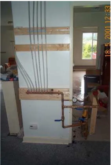
experiments in accordance with NFPA 13D, "Standard for the Installation of Sprinkler Systems in One- and Two-Family Dwellings and Mobile Homes" [1]. The water supply was fed to the system manifold (made of a 25.4 mm diameter copper tube, with 8 outlets of 12.7 mm diameter) located in the kitchen area, shown in Figure 4. The manifold included a pressure gauge and shutoff valves. The 8 manifold outlets were connected to the system plastic piping. Figure 5 shows a schematic drawing of the sprinkler system with 11 sprinkler heads and 2 plumbing fixtures. The static pressure of the water supply to the system was 552 kPa (80 psi). The system covered the entire ground floor and the recreation room of the test house. The system used Reliable®*quick response sprinkler heads with a temperature rating of 68.3°C (155°F).
*
Certain commercial products are identified in this report in order to adequately specify the experimental procedure. In no case does such identification imply recommendations or endorsement by the National Research Council of Canada, nor does it imply that the product or material identified is the best available for the purpose.
Each sprinkler head was screwed onto a multi-port fitting with connections to 4 water pipe lines. The sprinkler system used cross-linked-polyethylene pipes (with a diameter of 12.7 mm). These pipes were rated for 1103 kPa (160 psi) at 23°C (73.4°F), 896 kPa (130 psi) at 49°C (120°F), 689 kPa (100 psi) at 82°C (180°F) and 552 kPa (80 psi) at 93°C (200°F). The pipes and fittings were installed in the attic space for the sprinkler heads on the ground-floor ceiling. In the recreation room, the pipes and fittings were installed, without protection, on the open wood joists at the height of the furring, as shown in Figure 6. The system installed for this represents a common system for residential dwellings of this type.
Table 1 shows designed flow rates for each sprinkler head. Flow verification tests were performed. A flow test kit was attached to the multi-port fitting for sprinkler Head #8, including a flow control valve, a pressure gauge and a water bucket. Table 2 shows the results of the flow verification tests, including the pressure at the manifold, the pressure and the flow rate at the multi-port fitting for sprinkler Head #8. Tests were conducted with plumbing fixture valves being closed. Flow verification tests were also conducted with one plumbing fixture valve being open. For both cases, the actual flow rates for sprinkler Head #8 were equal to or greater than the design values.
Table 1 – Calculated Flow (L/min) at Various Manifold Pressures
Manifold Pressure kPa → (psi) → Sprinkler Head # ↓ 103 (15) 138 (20) 172 (25) 207 (30) 241 (35) 310 (45) 414 (60) 552 (80) 689 (100) 1 (bedroom 1) 36.3 41.6 46.5 50.7 54.9 62.1 71.9 82.9 92.7 2 (recreation room) 36.0 41.6 46.2 50.7 54.9 62.1 71.5 82.9 92.7 3 (recreation room) 36.3 41.6 46.2 50.7 54.9 62.1 71.5 82.9 92.7 4 (living room) 35.2 40.5 45.0 49.2 53.4 60.2 69.6 80.6 90.5 5 (living room) 36.3 42.0 46.5 51.1 55.3 62.5 72.3 83.6 93.5 6 (bathroom) 33.3 38.6 43.1 46.9 50.7 57.5 66.6 77.2 86.7 7 (hallway) 32.5 37.5 42.0 45.8 49.6 56.4 65.1 75.3 84.4 8 (dining room) 35.6 40.9 45.4 49.6 53.7 60.9 70.4 81.4 91.2 9 (foyer) 35.2 40.5 45.4 49.6 53.7 60.9 70.4 81.4 90.8 10 (kitchen) 34.8 39.7 44.7 48.8 52.6 59.8 68.9 79.9 89.3 11 (bedroom 2) 36.7 42.0 46.9 51.1 55.3 62.8 72.3 83.6 93.9
Table 2 – Results of Flow Verification Tests
Pressure at manifold kPa (psi) Pressure at Head #8 kPa (psi) Flow at Head #8 L/min (gpm) Plumbing fixture valve 241 (35) 172 (25) 53.0 (14) close 241 (35) 165 (24) 56.8 (15) close 172 (25) 117 (17) 49.2 (13) fully open
124 (18) 103 (15) not measured fully open
3.0 FIRE EXPERIMENTS
Table 3 shows a matrix of fire experiments. NRC conducted 2 experiments with fire origin in the recreation room, 1 experiment with fire origin in the ground floor bedroom and 1 experiment with fire origin in the living room with fuels typically found in an occupied residence. In each experiment, the flowing pressure at the manifold was 241 kPa (35 psi) during sprinkler spray. Smoke detectors, carbon monoxide detectors and heat detectors were installed in the experimental house. Measurement included temperatures in the fire room and egress route, CO and CO2 concentrations, activation times of sprinklers and smoke, heat and CO detectors, and video records of smoke movement (detailed description for each experiment is in the following subsections). The experiment procedure was as follows:
1. Verification of experiment layout, instrumentation and data acquisition; 2. t = 0 (time zero), starting data acquisition system;
3. t = 2 minute, igniting fuel; 4. t = tSP, sprinkler activation;
5. t = tSP + 10 minutes, stopping water supply; 6. Sending fire-fighter into the house; and 7. Ending the experiment.
Table 3 – Experiment Matrix
Test Date Fire Fuel Window Door
1 May 15, 2001 3:59 p.m.
near corner of recreation room
wastebasket, drape, sofa, end table, etc.
close close 2 May 16, 2001
10:47 a.m.
under pipes in centre of recreation room
upholstered chair close close 3 May 16, 2001
4:20 p.m.
near corner of bedroom #1
queen size mattress and box, etc.
close open 4 May 18, 2001
9:48 a.m.
near corner of living room
sofa, chair, end table, etc.
close none
3.1 Test 1
3.1.1 Experimental Set-up of Test 1
The first experiment was conducted in the recreation room, which was 5.9 m long, 3.8 m wide and 2.3 m high with additional cavity of open wood joists (an additional 0.25 m to the room height). Two sprinkler heads were spaced at 3.55 m apart. The plastic pipes and fittings were all exposed on the open wood joists without shielding. Figure 7 is a schematic drawing of the recreation room and experiment set-up. Figure 8 is clockwise snapshots of the recreation room with the set-up.
As shown in Figure 8, furniture in the recreation room included a leather chair, a
bookshelf (0.20 m x 0.61 m x 1.02 m), a sofa, a wooden coffee table, a wooden end table, and a chair with a long curtain behind. The ignition source was a wastebasket beside the end table in the corner and between the sofa and the chair. The wastebasket was filled with newspaper
(approximately 100 sheets) which touched the curtain. Because the furniture was very damp, a small amount of diesel (100 ml) was dripped onto the sofa arm for ease of ignition.
Thermocouples (TCs) were used to measure temperatures at various locations. A TC was put on the sofa arm that was beside the wastebasket to measure the temperature near the fire. Heat exposure of the unprotected cross-linked-polyethylene pipes was measured using a TC installed on the surface of the pipe at the position that was closest to the fire. Another TC was installed on the plywood in the cavity of the open wood joists, 0.25 m right above the pipe surface TC.
Three TC trees were also used in this experiment. Each TC tree consisted of 2 thermocouples, one at the height of 2.23 m and the other at the height of 1.60 m above the floor. A TC tree was installed 0.20 m beside each of the 2 sprinkler heads (the top TC was 76 mm below the furring) inside the recreation room. A small aluminum shield was used to shield each thermocouple on the TC tree from water spray. The third TC tree was installed in front of the door outside the recreation room.
Concentrations of carbon monoxide and carbon dioxide were measured using a
Siemens infrared gas analyzer (0-20 mA range for 0-1% CO and 0-4% CO2). The gas-sampling probe was located inside the recreation room at 1.60 m height, 1.49 m to the exterior wall and 0.66 m to the partition wall.
A commercial heat detector was installed on the furring, midway between the 2 sprinkler heads inside the room. The heat detector would activate either when the ceiling temperature reaches 57ûC (135ûF) or increases at a rate of 8.4ûC/min (15ûF/min) and more. The electric circuit inside the heat detector has normally open contacts. When the temperature or its rate of rise reaches the pre-set threshold, the electric circuit becomes a closed one by closed contacts, which can trigger fire alarm devices.
A commercial ionisation-photoelectric combined smoke alarm was installed outside the recreation room 0.5 m in front of the door on the hallway ceiling.
3.1.2 Experimental Results of Test 1
The fire was started by igniting the newspaper in the wastebasket. The door of the recreation room was then closed. The sofa arm started to burn 1 minute after the ignition. About 1 and half minutes after the ignition, the flame developed more than 1 m high, involving the sofa, end table and drape and the smoke layer reached the eye level.
One sprinkler head (#2) was actuated 114 s after the ignition. Within 26 seconds, the water spray from this single sprinkler head controlled the fire and confined the fire to the space under the end table. The flame became obscured 91 seconds after sprinkler activation due to loss of visibility from smoke build-up.
Table 4 shows activation times for the sprinkler, heat detector and smoke detector and associated temperatures at various locations as well as CO concentrations. The heat detector was first actuated 10 s earlier than the sprinkler. The heat detector was actuated by the rate of temperature rise since the nearby ceiling temperature was below the fixed threshold
temperature of 57ûC for the thermostat at that time. The smoke detector actuated 4 s later than the sprinkler. This was due to the fact that the smoke detector was located outside of the fire
room whose door was closed. The CO concentration inside the room was 100 ppm at the beginning of the water spray and 500 ppm at the end of the water spray. The maximum concentration of CO2 was 1.5% during the water spray.
Water supply to the sprinkler was shut off after 270-s water spray at the request of Wirsbo staff. Firefighters were sent into the recreation room. There was no visibility in the room and the fire was underneath the end table. When firefighters opened the window and started a fan for ventilation, the fire underneath the end table flared up and required suppression.
Figures 9 and 10 show profiles for temperatures at various locations and for the CO concentration inside the recreation room. It shows that the sprinkler quickly controlled the fire and the room was cooled down to below 20ûC during the water spray. After the water supply was shut off and firefighters started to ventilate the room, the room temperatures rose again because the fire smouldering underneath the end table re-developed into a flaming one, and the CO concentration reached a new peak. This fire was put out manually by the firefighters. The temperatures in the hallway outside the recreation room were basically not affected by the fire inside the room until the room door was opened.
The plastic pipe surface temperature at the position closest to the fire was below 50°C during the test. The exposed pipes and fittings had no visible damage during this experiment.
Figure 11 shows photographs of the recreation room after this experiment. The side and back of the sofa were badly burnt, the underside of the end table was charred, and the drape was partially burnt off. The walls and open wood joists of the room had soot deposition but no major damage.
Table 4 – Results of Test 1 (Basement Recreation Room, May 15, 2001)
Device Location Activation Maximum
Actuated sprinkler Head #2 114 s * Heat detector mid-point between Heads #2 and #3 104 s Dual smoke alarm hallway ceiling 118 s
TC1 TC tree beside Head #3 – top 55.9ûC * 63.2ûC TC2 TC tree beside Head #3 – mid 34.9ûC * 43.7ûC TC3 TC tree beside Head #2 – top 132.5ûC * 132.5ûC TC4 TC tree beside Head #2 – mid 33.9ûC * 35.1ûC
TC5 open joist cavity 47.8ûC * 52.4ûC
TC6 pipe closest to fire 44.1ûC * 44.1ûC TC8 hallway TC tree – top 14.4ûC * 14.5ûC TC9 hallway TC tree – mid 13.3ûC * 13.3ûC
TC11 sofa arm 200.9ûC * 220.6ûC
Gas analyzer nose height inside recreation room 100 ppm CO * 500 ppm CO
Note: Activation times are counted from ignition. * Values correspond to the time when the sprinkler was actuated.
3.2 Test 2
3.2.1 Experimental Set-up of Test 2
The second experiment was also conducted in the recreation room. The sprinkler heads and the heat detector were replaced with new ones. The 2 TC trees beside the sprinkler heads, the TC tree in the hallway, the gas-sampling probe, and the heat detector stayed at the same positions as in Test 1.
Figure 12 shows the set-up for the second experiment. A reclining chair was placed midway between the 2 sprinklers and used as the fire source. The chair was located directly underneath the exposed pipes, as shown in Figure 13. A cloth was hung on an arm of the chair and reached down to a small fuel pan placed beside and under the chair. A small amount of diesel (150 ml) was dripped onto the arm and the cloth and into the fuel pan for ease of ignition. This arm was at an equal distance to both sprinkler heads. A TC was placed on the chair to measure the temperature near the fire. Two TCs were installed right above the chair, one on the surface of the unprotected pipe and the other on the plywood in the cavity of the open wood joists.
3.2.2 Experimental Results of Test 2
The fire was started by igniting the cloth hung on the chair. The door of the recreation room was then closed. Within 44 s, the flame developed to about 1.3 m high, involving the top and lower part of the arm side. Table 5 shows activation times for the sprinkler and heat detector and associated temperatures at various locations as well as CO concentrations.
The heat detector actuated 52 s after the ignition, by the rate of temperature rise when the nearby ceiling temperature was 37oC (the ceiling temperature further increased to beyond the fixed threshold temperature of the heat detector).
Within 54 s from the ignition, the flame involved the entire arm side and further developed to the back of the recliner. A minute later, the flame gradually slowed down and became smaller. As shown in Figure 14, the temperatures inside the room started to drop 105 s after the ignition. The fire on the chair changed to mostly smouldering mode with heavy smoke accumulation in the room. The room temperatures lowered to around 30oC within 330 s after the ignition. At that time, the visibility in the room was completely lost and only a twinkling flame from the chair was visible on the video.
Afterwards, the fire was slowly built up again for another 7 minutes as indicated by the rising temperature profiles shown in Figure 14. The peak temperatures reached 178oC in the open joist space and 140oC on the plastic pipe when one sprinkler head (#2) actuated 740 s after the ignition. This single sprinkler head (#2) controlled and contained the fire. Fire was quickly knocked down. Within 1 minute of the sprinkler activation, flame was not visible on the surface of the chair. However, the thermocouple on the chair indicated there was still fire inside the back cushion.
The temperatures in the hallway were basically unchanged. Since the door to the recreation room was closed, the hallway temperatures were around 10°C, close to the ambient temperature.
Figure 15 shows a CO concentration profile inside the room. The CO concentration was 1000 ppm when the sprinkler was actuated. A CO concentration above 1500 ppm is considered to be immediately dangerous to life and health [2]. The maximum CO concentration was
1800 ppm at the end of the experiment.
After the sprinkler sprayed for a total of 10 minutes, the water supply to the sprinkler was shut off and firefighters were sent into the room. The firefighters vented the room and manually extinguished the fire that was still smouldering inside the back cushion. Figure 16 shows a photograph taken after the experiment.
The plastic pipes and fittings were exposed twice, during the experiment, to the
temperature of above 93°C, the first for 40 s and the second for 100 s, with the peak exposure of 140oC. It was observed after this test that the exposed pipes and fittings were not visibly damaged. The same pipes and fittings continued to be used in the subsequent experiment.
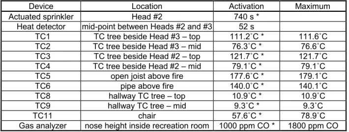
Table 5 – Results of Test 2 (Basement Recreation Room, May 16, 2001)
Device Location Activation Maximum
Actuated sprinkler Head #2 740 s * Heat detector mid-point between Heads #2 and #3 52 s
TC1 TC tree beside Head #3 – top 111.2ûC * 111.6ûC TC2 TC tree beside Head #3 – mid 76.3ûC * 76.6ûC TC3 TC tree beside Head #2 – top 121.7ûC * 121.7ûC TC4 TC tree beside Head #2 – mid 79.1ûC * 79.1ûC TC5 open joist above fire 177.6ûC * 179.1ûC
TC6 pipe above fire 140.0ûC * 140.1ûC
TC8 hallway TC tree – top 10.9ûC * 10.9ûC TC9 hallway TC tree – mid 9.3ûC * 9.3ûC
TC11 chair 57.6ûC * 78.9ûC
Gas analyzer nose height inside recreation room 1000 ppm CO * 1800 ppm CO
Note: Activation times are counted from ignition. * Values correspond to the time when the sprinkler was actuated.
3.3 Test 3
3.3.1 Experimental Set-up of Test 3
The third experiment was conducted in a bedroom (#1) on the ground floor. Figure 17 shows the set-up for the third experiment. The bedroom was 3.94 m long, 3.20 m wide and 2.44 m high with one sprinkler head (#1) inside the bedroom. The bedroom door was kept open during the experiment.
A queen size bed was placed 0.15 m from a wall. A small fuel pan was placed under the bed, with the bedspread touching the pan, as shown in Figure 18. A small amount of diesel (150 ml) was poured into the pan as an ignition source.
A TC was placed on the bed near the mattress corner 0.30 m from both edges, which was near the ignition point. A TC was installed in the attic space inside the drywall ceiling (6 mm inside) right above that ignition point.
As shown in Figure 18, a TC tree and a heat detector were installed 0.20 m beside the sprinkler head in the bedroom. The TC tree consisted of 2 thermocouples, one at the height of 2.36 m and the other at the height of 1.60 m above the floor (the top TC was 76 mm below the ceiling).
Another TC tree and a photoelectric smoke detector were installed 0.2 m beside the sprinkler head in the corridor, as shown in Figure 19. A commercial carbon monoxide detector was also installed in the corridor at the 0.30 m height. The CO detector continuously monitored for CO and displayed the CO level (range from 0 to 999 ppm) every minute. The CO alarm would sound an alarm immediately when the CO concentration reached 600 ppm and above.
3.3.2 Experimental Results of Test 3
The fire was started by igniting the diesel in the fuel pan. In 1 minute, the fire was fully developed to 1.5 m high in the bedroom corner and light smoke moved to the corridor.
The smoke detector in the corridor actuated 45 s after the ignition. At that time, the smoke layer was still close to the ceiling and the visibility in both the bedroom and the corridor were still very good.
The heat detector inside the bedroom actuated 57 s after the ignition. The heat detector was actuated by the rate of temperature rise since the bedroom ceiling temperature was only 45oC at that time, below the fixed threshold temperature for the detector. Smoke was seen to move to the foyer ceiling at the same time. About 71 s after the ignition, the smoke layer dropped to eye level in the corridor and the foyer visibility was still acceptable for evacuation purposes.
Figure 20 shows temperature profiles at various locations during the experiment.
Table 6 shows the temperatures at various locations when the sprinkler inside the bedroom was actuated. The sprinkler head (#1) inside the bedroom actuated 84 s after the ignition. This single sprinkler head controlled and contained the fire under the bed in 1 minute. A few seconds later, visibility was lost in the bedroom and the nearby corridor.
The first non-zero display (13 ppm) on the corridor CO detector appeared 2 and one half minutes after the sprinkler activation. After 3 non-zero displays (13, 24 and 45 ppm, one per minute), the entire corridor and foyer became dark and visibility was completely lost. The CO alarm sounded 7.5 minutes (453 s) after the sprinkler activation, indicating that the CO
concentration in the corridor reached 600 ppm.
The water supply to the sprinkler was shut off 10 minutes after the sprinkler activation. Firefighters entered the house, opened the bedroom window and used a fire hose to spray water onto the bed. After the visibility in the house improved, the display on the CO detector was seen as 999 ppm, which was the upper limit of this device. This means that the CO concentration had gone beyond 1000 ppm at the detector location during the experiment. Figure 21 shows the CO concentration profile at the CO detector location in the corridor.
Figure 22 shows a picture of the aftermath. Since the sprinkler contained the fire under the bed, the top of the bed was not burnt. The major damage was underneath the bed (the box and the underside of the mattress). It should be noted that, after the experiment, the mattress and the box continued to smoulder, which triggered the smoke alarm again. Smoke was seen to arise in the bedroom corner underneath the bed. Firefighters were called in again to
extinguish the smouldering fire inside the mattress and box and to remove them from the house.
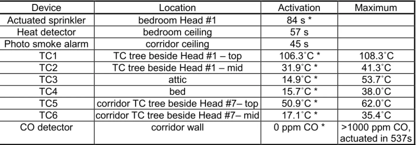
Table 6 – Results of Test 3 (1st Floor Bedroom #1, May 16, 2001)
Device Location Activation Maximum
Actuated sprinkler bedroom Head #1 84 s * Heat detector bedroom ceiling 57 s Photo smoke alarm corridor ceiling 45 s
TC1 TC tree beside Head #1 – top 106.3ûC * 108.3ûC TC2 TC tree beside Head #1 – mid 31.9ûC * 41.3ûC
TC3 attic 14.9ûC * 53.7ûC
TC4 bed 15.7ûC * 38.0ûC
TC5 corridor TC tree beside Head #7– top 50.9ûC * 62.0ûC TC6 corridor TC tree beside Head #7– mid 17.1ûC * 35.4ûC CO detector corridor wall 0 ppm CO * >1000 ppm CO,
actuated in 537s
Note: Activation times are counted from ignition. * Values correspond to the time when the sprinkler was actuated.
3.4 Test 4
3.4.1 Experimental Set-up of Test 4
The fourth experiment was conducted in the living room. The living room was 7.19 m long, 3.73 m wide and 2.44 m high, connecting to the dining room of 4.00 m long and 3.14 m wide without partition. Figure 23 shows a schematic of the set-up for the fourth experiment.
Four TC trees were also used in this experiment to measure temperatures at various locations. Each TC tree consisted of 2 thermocouples, one at the height of 2.36 m and the other at the height of 1.60 m above the floor. A TC tree was installed 0.20 m beside each of the 3 sprinkler heads in the living and dinning rooms (the top TC was 76 mm below the ceiling). The fourth TC tree was installed in the foyer area.
A commercial heat detector was installed on the ceiling, midway between the 2 sprinkler heads in the living room (1.78 m to each of the two sprinkler head). A commerical carbon monoxide detector was installed in the foyer at the 0.30 m height. The CO detector
continuously monitored for CO and displayed the CO level (range from 0 to 999 ppm) every minute. The CO alarm would sound immediately when the CO concentration reached 600 ppm.
As shown in Figure 24, furniture in the living room included a TV set, a leather chair, a wooden end table and a sofa with a curtain behind. A cloth was hung on the chair and on the sofa, reaching down to a fuel pan placed in between. A small amount of diesel (125 ml) was dripped onto the cloth and the pan for ease of ignition. A TC was placed on the sofa near the ignition point to measure the temperature near the fire. A TC was installed in the attic space inside the drywall ceiling (6 mm inside the gypsum board) right above that ignition point as outlined in the UL standard to check for structural damage [3].
A vertical run of the plastic pipe from the attic space to the basement was exposed in the living room. A TC was installed on the pipe surface 25 mm below the ceiling to measure the exposing temperature, as shown in Figure 24.
3.4.2 Experimental Results of Test 4
The heat detector actuated 39 s after the ignition by the rate of temperature rise when the nearby ceiling temperature was between 35ûC and 50ûC. An upper smoke layer of half-meter thickness was formed in the living room within 50 s from the ignition.
A single sprinkler head (#4) actuated 59 s after the ignition and it controlled and
contained the fire. Thirty seconds after the sprinkler activation, the smoke layer quickly dropped and the living room became completely dark with no visibility. The display on the CO detector in the foyer still indicated a zero CO level at that time. The foyer also lost visibility 56 s after the sprinkler activation and the display on the CO detector was invisible.
The water supply to the sprinkler was shut off 10 minutes after the sprinkler activation. When firefighters were sent into the house, they found no flaming fire remaining in the living room. After ventilation, the display on the CO detector became visible and the first display was 254 ppm. The displayed CO level continued to decrease. This indicated that the CO
concentration at the detector location was greater than 254 ppm during the experiment. On the other hand, the audio signal from the video record showed that the alarm of the CO detector was not actuated, indicating that the CO concentration was less than 600 ppm during the experiment.
Figure 25 shows temperature profiles at various locations during the experiment. The temperatures when the sprinkler actuated are shown in Table 7.
Figure 26 shows the living room after the experiment. Since the sprinkler successfully contained the fire in the room corner, the fire damage was limited to one arm of each sofa and chair. The vertical pipe in the living room was exposed to a maximum temperature of 74oC during the fire experiment, not exceeding its rated temperature yet. It was observed after this test that the exposed pipe had no visible damage.
Table 7 – Results of Test 4 (1st Floor Living Room, May 18, 2001)
Device Location Activation Maximum
Actuated sprinkler Head #4 59 s *
Heat detector mid-point between Heads #4 and #5 39 s
TC5 foyer TC tree – top 51.0ûC * 85.8ûC TC6 foyer TC tree – mid 18.3ûC * 47.8ûC TC21 TC tree beside Head #4 – top 103.0ûC * 103.0ûC TC22 TC tree beside Head #4 – mid 22.9ûC * 48.2ûC TC23 TC tree beside Head #5 – top 69.7ûC * 92.1ûC TC24 TC tree beside Head #5 – mid 18.3ûC * 50.9ûC
TC25 sofa 46.3ûC * 47.6ûC
TC26 attic 10.2ûC * 32.9ûC
TC27 pipe 65.7ûC * 73.9ûC
TC28 dining room TC tree beside Head #8 – top 74.6ûC * 100.5ûC TC29 dining room TC tree beside Head #8 – mid 26.6ûC * 55.5ûC CO detector foyer wall 0 ppm CO * < 600 ppm CO,
not actuated
Note: Activation times are counted from ignition. * Values correspond to the time when the sprinkler was actuated.
3.5 Comparison of Temperatures at Various locations
The quick response sprinkler heads used in the experiments were rated at the
temperature of 68.3°C (155°F). When this rated temperature was reached in the experiments, the sprinkler head that was later actuated had a delay time before discharging water. The delay time was 10 s for Tests 1, 3 and 4 and was 160 s for Test 2. When the sprinkler was actuated, the temperature of the top TC beside the actuated sprinkler was significantly higher than the rated temperature, and was also 15 to 30ûC higher in Tests 1 and 2 (recreation room) than in Test 3 (bedroom) and Test 4 (living room).
The maximum temperature that the plastic pipes and fittings were exposed to was 140oC in Test 2. After the exposure of temperatures above 93°C at 552 kPa for 140 s, the pipes and fittings were not visibly damaged, the sprinkler system was successfully actuated to control the fire, and these same pipes and fittings continued to be used in the subsequent experiment.
The fire compartment was cooled down to below 20°C by the water spray from the sprinkler in each experiment. This temperature is low enough to allow safe evacuation of occupants and deployment of firefighting personnel.
During Tests 1 and 2 where the fire compartment door was kept closed, the
temperatures on the egress route were around the ambient temperatures. During Tests 3 and 4 where the fire compartments were open, the temperatures on the egress route were affected by heat convection from hot gases.
4.0 CONCLUSIONS
NRC completed a series of fire experiments of a cross-linked-polyethylene pipe sprinkler system in a residential dwelling at the Kemano Village. One of the purposes of this project was to study the system effectiveness in controlling fire. This residential sprinkler system was designed to prevent flashover within the compartment of fire origin and to allow response time for the fire department. In all 4 experiments, a single sprinkler head controlled and contained the fire within the fire origin within 1 minute of the sprinkler activation. The sprinkler water spray cooled down the fire compartment before firefighters were sent into the house. Since the sprinkler successfully controlled the fire in each experiment, the fire damage was limited to the furniture that was near the ignition source. The walls, open wood joists or ceiling of the fire room had soot deposition but no major damage. The sprinkler heads that were installed on the open wood joists at the height of the furring strips tended to actuate at higher temperatures than the heads that were installed under the gypsum board ceiling.
Another purpose of this project was to study the behaviour of unprotected cross-linked-polyethylene pipes under fire conditions. The maximum temperature that the plastic pipes and fittings were exposed to was 140oC in the recreation room with open wood joists. After the exposure of temperatures above the rated temperature of 93°C at 552 kPa for 140 s, the pipes and fittings were not damaged, the sprinkler system was successfully actuated to control the fire, and these same pipes and fittings were used in the subsequent experiment.
During the experiments, the temperatures on the egress route were around the ambient temperatures when the fire compartment door was kept closed.
In addition to the performance study of the sprinkler system, the effectiveness of heat, smoke and carbon monoxide detectors was also investigated in the experiments. As expected, the heat detector was always actuated earlier than the sprinkler. The rate of temperature rise triggered the detector. A smoke alarm, installed on the egress route, was actuated before the sprinkler activation when the fire room was open to the egress route; it was actuated after the sprinkler activation when the fire room door was closed. The CO concentration at the
measurement location was below the dangerous level when the sprinkler was actuated in each experiment.
NRC has gained understanding of performance issues of plastic pipe sprinkler systems using typical residential fires, using this unique KPSI opportunity. Technical data obtained from the Kemano experiments will guide further studies with an increased fire challenge to the sprinkler systems.
5.0 ACKNOWLEDGEMENTS
This study was conducted as a joint research project between the National Research Council of Canada and Wirsbo Canada Ltd. NRC acknowledges Wirsbo Canada's contribution in co-funding this project, designing the sprinkler system, providing all system materials,
installing the system and sending a crew of staff to the experiment site. NRC also
acknowledges the logistic support from the B.C. Office of the Fire Commissioner and Alcan Smelters and Chemicals Ltd.
6.0 REFERENCES
1. NFPA 13D, "Standard for the Installation of Sprinkler Systems in One- and Two-Family Dwellings and Manufactured Homes," National Fire Protection Association, Quincy, MA, U.S.A., 1999 Edition, pp. 1-29.
2. Occupational Safety and Health Administration, "OSHA Regulated Hazardous Substances," Noyes Data Corp., Park Ridge, 1990.
3. UL 1626, "Residential Sprinklers for Fire-Protection Service", Underwriters Laboratories, Northbrook, IL, U.S.A., 1994, 2nd ed., Section 26.1.1 (d).
Time (s) 0 100 200 300 400 500 600 700 800 900 1000 T e mper atur e ( o C) 0 50 100 150 200 250
TC tree beside Head #3 - top TC tree beside Head #3 - mid TC tree beside Head #2 - top TC tree beside Head #2 - mid open joist cavity
pipe surface
hallway TC tree - Top hallway TC tree - mid sofa arm
Time (s) 0 100 200 300 400 500 600 700 800 900 1000 CO Concent ra ti on ( % ) 0.00 0.05 0.10 0.15 0.20 0.25
Figure 13. Chair directly under exposed pipes, with thermocouples installed on the chair, unprotected pipe and in the cavity of open wood joist and with diesel dripped onto the arm, cloth and fuel pan (Test 2).
Time (s) 0 200 400 600 800 1000 1200 1400 1600 1800 T e mper atur e ( o C) 0 20 40 60 80 100 120 140 160 180 200
TC tree beside Head #3 - top TC tree beside Head #3 - mid TC tree beside Head #2 - top TC tree beside Head #2 - mid open joist above fire
pipe above fire hallway TC tree - top hallway TC tree - mid chair
Time (s) 0 200 400 600 800 1000 1200 1400 1600 1800 CO Concent ra ti on ( % ) 0.00 0.02 0.04 0.06 0.08 0.10 0.12 0.14 0.16 0.18 0.20
Figure 19. Sprinkler head, TC tree, photoelectric smoke detector and carbon monoxide detector in the corridor.
Time (s) 0 100 200 300 400 500 600 700 800 900 1000 T e mper atur e ( o C) 0 20 40 60 80 100 120
bedroom TC tree beside Head #1 - top bedroom TC tree beside Head #1 - mid attic
bed
corridor TC tree beside Head #7 - top corridor TC tree beside Head #7 - mid
Time (s) 0 100 200 300 400 500 600 700 800 900 1000 1100 1200 1300 1400 1500 1600 CO Conc entr a tion (% ) 0.00 0.02 0.04 0.06 0.08 0.10
Figure 22. Photograph of the bedroom, underside of the mattress and the boxspring after Test 3.
Time (s) 0 100 200 300 400 500 600 700 800 900 1000 T e mper atur e ( o C) 0 20 40 60 80 100 120
foyer TC tree - top foyer TC tree - mid
TC tree beside Head #4 - top TC tree beside Head #4 - mid TC tree beside Head #5 - top TC tree beside Head #5 - mid sofa
attic pipe
dining room TC tree beside Head #8 - top dining room TC tree beside Head #8 - mid