HAL Id: hal-01370185
https://hal.archives-ouvertes.fr/hal-01370185
Submitted on 22 Sep 2016
HAL is a multi-disciplinary open access
archive for the deposit and dissemination of
sci-entific research documents, whether they are
pub-lished or not. The documents may come from
teaching and research institutions in France or
abroad, or from public or private research centers.
L’archive ouverte pluridisciplinaire HAL, est
destinée au dépôt et à la diffusion de documents
scientifiques de niveau recherche, publiés ou non,
émanant des établissements d’enseignement et de
recherche français ou étrangers, des laboratoires
publics ou privés.
Numerical Simulation of Cochlear-Implant Surgery:
Towards Patient-Specific Planning
Olivier Goury, Yann Nguyen, Renato Torres, Jeremie Dequidt, Christian
Duriez
To cite this version:
Olivier Goury, Yann Nguyen, Renato Torres, Jeremie Dequidt, Christian Duriez. Numerical
Simula-tion of Cochlear-Implant Surgery: Towards Patient-Specific Planning. 19th InternaSimula-tional Conference
on Medical Image Computing & Computer Assisted Intervention (MICCAI 2016), Oct 2016, Athènes,
Greece. pp 500-507. �hal-01370185�
Numerical Simulation of Cochlear-Implant
Surgery: Towards Patient-Specific Planning
Olivier Goury1,2, Yann Nguyen2, Renato Torres2, Jeremie Dequidt1, and
Christian Duriez1
1 Inria Lille - Nord Europe, Universit´e de Lille 1 - France
2
Inserm, UMR-S 1159, Universit´e Paris VI Pierre et Marie Curie - France
Abstract. During Cochlear Implant Surgery, the right placement of the implant and the minimization of the surgical trauma to the inner ear are an important issue with recurrent fails. In this study, we reproduced, using simulation, the mechanical insertion of the implant during the surgery. This simulation allows to have a better understanding of the failing cases: excessive contact force, buckling of the implant inside and outside the cochlea. Moreover, using a patient-specific geometric model of the cochlea in the simulation, we show that the insertion angle is a clinical parameter that has an influence on the forces endured by both the cochlea walls and the basilar membrane, and hence to post-operative trauma. The paper presents the mechanical models used for the implant, for the basilar membrane and the boundary conditions (contact, friction, insertion etc...) and discuss the obtained results in the perspective of us-ing the simulation for plannus-ing and robotization of the implant insertion. Keywords: Cochlear Implant Surgery, Cochlea Modeling, FEM
1
Introduction
Scala vestibuli Scala tympani Spiral Ganglion Implant Basilar membraneFig. 2. Cross-section of a cochlea with implant inserted.
Cochlear implant surgery can be used for pro-foundly deafened patient, for whom hearing aids are not satisfactory. An electrode array is inserted into the tympanic ramp of the pa-tient’s cochlea (scala tympani). When well-inserted, this array can then stimulate the auditory nerve and provide a substitute way of hearing. However, as of today, the surgery is performed manually and the surgeon has only little perception on what happens in the cochlea while he is doing the insertion [1].
Yet, it is often the case that the implant gets blocked in the cochlea before being com-pletely inserted. Another issue is the fact this insertion can create trauma on the wall of the
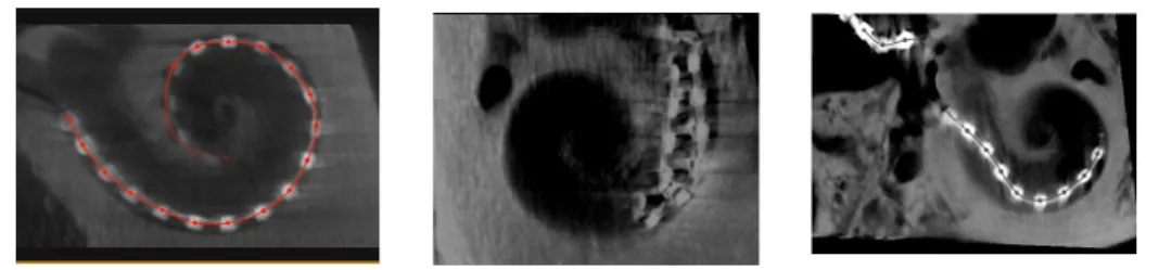
Fig. 1. Examples of 3 insertions with different outcomes, from left to right: successful insertion, failed insertion (folding tip), incomplete insertion.
cochlea as well as damaging the basilar membrane. This can lead to poor post-operative speech performances or loss of remaining acoustic hearing in lower frequencies that can be combined with electric stimulation. The simulation the insertion procedure would allow for great outcomes. Indeed, it can be used for surgery planning, where the surgeon wish to predict the quality of the insertion depending on various parameters (such as the insertion angle or the type of im-plant used) for a specific patient, or surgery assistance in the longer term (where the procedure would be robot-based). Cochlear implant surgery was simulated in [2, 3] respectively in 2 and 3 dimensions, on simplified representations of the cochlea. These works allowed to make first predictions about the forces endured by the cochlea walls.
In this contribution, we develop a framework able to accurately simulate, in three dimensions, the whole process of the implant insertion into a patient-specific cochlea, including the basilar membrane deformation. The simulation is done using the finite element method and the SOFA framework3. The implant is modelled using the beam theory, while shell elements are used to define a computational model of the basilar membrane. The cochlea walls are modelled as rigid which is a common assumption [4] due to the bony nature of the cochlea.
2
Numerical Models and Algorithms
In this section, we describe the numerical model used to capture the mechanical behavior and the specific shapes of the cochlear implant and the basilar mem-brane. Moreover, the computation of the boundary conditions (contacts with the cochlea walls, insertion of the implant) are also described, as they play an important role in this simulation.
Implant Model: The implant is made of silicone and has about 20 electrodes (depending on the manufacturer) spread along its length. It is about half a millimetre thick and about two to three centimetre long. Its thin shape makes it possible to use beam elements to capture its motion (see figure 3). Its dynamics can be modelled as follows:
M ˙v = p − F(q, v) + HTλ, (1)
3
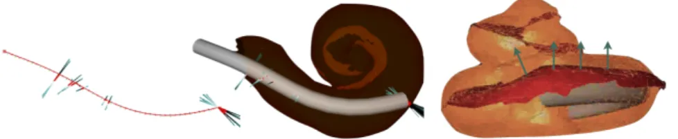
Fig. 3. (Left) The implant is modeled using beam elements and, (middle) its motion is constrained by contact and friction response to collision with cochlear walls. (right) Contact forces induces strain on the Basilar membrane.
where M is the mass matrix, q is the vector of generalised coordinates (each node at the extremity of a beam contains three spatial degrees of freedom and three angular degrees of freedom), v is the vector of velocities. F represents the internal forces of the beams while p gathers the external forces. λ is the vector of contact forces magnitudes with either the cochlea wall or the basilar membrane, and H gathers the contact directions. The computation of the internal forces F relies on the assumption of an elastic behavior, which brings back the electrode to its rest shape when external forces are released. In practice, we defined a Young’s modulus of around 250 MPa as in [5] and we rely on the assumption of a straight rest shape to model the electrode we used for the experiments. However some pre-shaped electrodes exist, and our implementation of the beam model supports the use of curved reference shape.
Basilar membrane model The basilar membrane separates two liquid-filled tun-nels that run along the coil of the cochlea: scala media and scala tympani (by which the implant is inserted). It is made of a stiff material but is very thin (about 4 µm) and thus very sensitive to the contact with the electrodes. During the insertion, even if the electrode is soft, the membrane will deform to com-ply with its local shape. In case of excessive contact force, the membrane will rupture: the electrode could then freely go in the scala media or scala vestibuli. This will lead to loss of remaining hearing, damages to auditory nerve dendrites and fibrosis. To represent the Basilar membrane, we use a shell model [6] that derives from a combination of a triangular in-plane membrane element and a triangular thin plate in bending. The nodes of the membrane that are connected with the walls of the cochlea are fixed, like in the real case.
Implant Motion : During the procedure, the implant is pushed (using pliers) through the round window which marks the entrance of the cochlea. To simplify the implant model, we only simulate the portion of the implant which is inside the cochlea. The length of the beam model is thus increased progressively during the simulation to simulate the insertion made by the surgeon. Fortunately, our beam model relies on continuum equations, and we can adapt the sampling of beam elements at each simulation step while keeping the continuity of the values of F. The position and orientation of the implant body may play an important role (see section 4), so these are not fixed. Conversely, we consider that the implant
is pushed at constant velocity, as a motorized tool for pushing the implant was used in the experiments.
Contact response on cochlear walls : The motion of the implant is constrained by contact and friction forces that appear when colliding the walls of the cochlea. To obtain an accurate simulation, the modeling of both geometry of the cochlea walls and physics of the collision response are important. To reproduce the geometry of the cochlea, we rely on images issued from cone-beam CT. The images are segmented using ITK-Snap and the surface of the obtained mesh are smoothed to remove sampling noise. Compared to previous work [2, 3], our simulations do not used a simplified geometric representation of the cochlear walls.
The contact points between implant and cochlea walls are detected using an algorithm that computes the closest distances (proximity queries) between the mesh and the centerline of the implant model. The algorithm is derived from [7]. At each contact point, the signed distance distance δn(q) between the centerline
and the corresponding point on the collision surface (along the normal direction of the surface) must be larger than the radius of the implant (δn(q) ≥ r). It
should be noted that this collision formulation creates a round shape at the tip of the implant which is realistic but badly displayed visually in the simulation. The contact force λn follows the Signorini’s law:
0 ≤ λn⊥ δn(q) − r ≥ 0 (2)
In addition to the precision, one advantage of this law is that there is no addi-tional parameters rather than the relative compliance of the deformable structure in contact. In the tangential direction, λtfollows Coulomb’s law friction to
repro-duce the stick/slip transitions that are observed in the clinical practice. At each contact point, the collision response is based on Signorini’s law and Coulomb’s friction using the solvers available in SOFA.
Unfortunately, the friction coefficient µ is one of the missing parameter of the simulation. Several studies have tried to estimate the frictional conditions between the electrode array of the implant and the endosteum lining and the wall of the tympani such as [8] or [9]. However experiments were performed ex-vivo on a relatively small set of samples and exhibit some important variability and heterogeneity. As a consequence, in section 4, we perform a sensitivity analysis of this parameter.
3
Experimental validation
As mentioned in the introduction, it is difficult to have an immediate feedback on how the implant deploys in the cochlea due to very limited workspace and visibility. This poor feedback prevents the surgeon to adapt and update his/her gesture to improve the placement of the implant. To have a better understanding of the behaviors and to simplify the measurements, we have conducted exper-iments of implant placement on temporal bones issued from cadavers. In this
a
c
b
d
Fig. 4. Experimental setup. Microdissected cochleae are molded into resin (a) and fixed to a 6-axis force sensor (c). A motorized uniaxial insertion tool (b) is used to push the electrode array into the scala tympani at a constant velocity. The whole setup is schemed in (d).
section, these experiments are presented as well as a comparison between the measurements and the simulation results.
Material : An custom experimental setup is built up to evaluate the forces endured by the scala tympani during the insertion of an electrode array at con-stant velocity. This setup is described in Figure 4. Recorded data: This setup allows to compare forces when performing a manual insertion and a motorized, more regular, insertion. With this setup, we are able to reproduce failure cases such as incomplete insertion or so-called folding tip insertion, as displayed in Figure 1.
Ability to reproduce incomplete insertions: The goal of this first comparison is to show if we can reproduce what is observed in practice using simulation. Due to contact and friction conditions and the fact that we work with living structures, it is never possible to reproduce the same insertion, even if the inser-tion is motorized. So we do not expect the simulainser-tion to be predictive. However, we show that the simulation is able to reproduce different scenarios of insertion (complete/incomplete insertion or folding tip). Like in practice, the first impor-tant resistance to the insertion of the implant appears in the turn at the bottom of the cochlea (like in the picture (middle) of Fig3.) This resistance create a buckling of the implant that limits the transmission in the longitudinal direction till the implant presses the cochlear walls and manages to advance again. If the resistance to motion is too large, the implant stays blocked. This differentiates a complete and incomplete insertion and is captured by the simulation. Evolution of the implant forces while performing the insertion: An indicator of the smooth-ness of the insertion is the force applied on the implant by the surgeon during the surgery. For minimising trauma, that force should typically remain low. Experi-mental data shows that this force generally increases as the insertion progresses. This is explained by the fact that as the implant is inserted, its surface of contact
Time(s) Time(s) Force(N) Force(N) 0 5 10 15 20 0.00 0 20 40 60 0.05 0.10 0.15 0.00 0.05 0.10 0.15
Tangent to the wall of the cochlea's entrance θ
Insertion angle
Fig. 5. (Left)Forces when performing motorized versus manual insertion using the setup presented in Figure 4. (Right) Dissected temporal bone used during experiments with the definition of the insertion angle θ: the angle formed by the implant and the wall of the cochlea’s entrance
onto the cochlea walls and the basilar membrane increases, leading to more and more friction. The force has a peak near the first turn of the cochlea wall (the basal turn). We see that the simulation reproduces this behaviour (See Figures 1 and 6).
4
Sensitivity of the results to mechanical and clinical
parameters
Many parameters can influence the results of the simulation. We distinguish the mechanical parameters (such as friction on the cochlea walls, stiffness of the implant, elasticity of the membrane, etc... ) and the clinical parameters, which the surgeon can control to improve the success of the surgery. In this first study, among all the mechanical parameters, we selected to study the influence of the friction, which is complex to measure. We show that the coefficient of friction has an influence on the completeness of the insertion but has less influence on the force that is applied on the basilar membrane (see Figure 7).
For the clinical parameters, we focus on the angle of insertion (see Figure 5). The position and orientation of the implant compared to the cochlea tunnels plays an important role in the easiness of inserting the implant. The anatomy makes it difficult to have a perfect alignment but the surgeon has still a certain freedom in the placement of the tube tip. Furthermore, his mental representation of the optimal insertion axis is related to his experience and even experts have a 7◦error of alignment [1]. We test the simulation with various insertion angles, from a aligned case with θ = 0 to a case where the implant is almost orthogonal to the wall entrance with θ = 85, and compare the outcome of the insertion, as well as the forces induced on the basilar membrane and the implant. Findings are displayed in Figure 7.
Length (mm)
Force (N)
Successful Insertion Folding tip Insertion Incomplete Insertion
Sim ulation Force(N) Length(mm) Length(mm) 0 5 10 15 20 25 0 5 10 15 20 25 Length(mm) 0 5 10 15 20 25 0.0 0.1 0.2 0.3 0.4 0.5 0.6 0.0 0.1 0.2 0.3 0.4 0.5 0.6 0.0 0.1 0.2 0.3 0.4 0.5 0.6 Force(N) Force(N) Simulation Experiment Simulation Experiment Simulation Experiment
Fig. 6. Comparison between experiments and simulation in 3 cases. We can see that the simulation can reproduce cases met in real experiments (see Figure 1). Regarding forces on the cochlea walls, the general trend of the simulation is similar to the experiments. To reproduce the folding tip case in the simulation, which is a rare in practice, the array was preplaced with a folded tip at the round window region, which is why the curve does not start from 0 length. In the incomplete insertion case, the force increases greatly when the implant reaches the first turn. The simulation curves stops then. This is because we did note include the real anatomy outside the entrance of the cochlea that would normally constrain the implant and lead the force to keep increasing.
5
Conclusion and future work
In this paper, we propose the first mechanical simulation tool that reproduces the insertion of the cochlear implant in 3D, using patient data. Several scenarios are considered and the results we obtained exhibit that several failures in the surgery can be reproduced in the simulator. Moreover similar pattern of forces against the cochlea’s wall are measured in experimental scenarios and their cor-responding simulations. From a quantitative standpoint, an analysis has been conducted to estimate the influence of the main parameters reported by clini-cians. This preliminary study could be extended with the following perspectives: first, we need to enrich our experimental study by considering several patients and different implants; second a (semi-)automatized framework should be con-sidered in order to generate patient-specific data from medical images in order to allow in a clinical time a virtual planning of the surgery. This work could be a first step towards the use of simulation in the planning of cochlear im-plant surgery or even robot-assisted surgery. This objective would require the use of accurate and validated bio-mechanical simulations of the whole procedure (anatomical structures and implant). In-vivo experiments may be necessary.
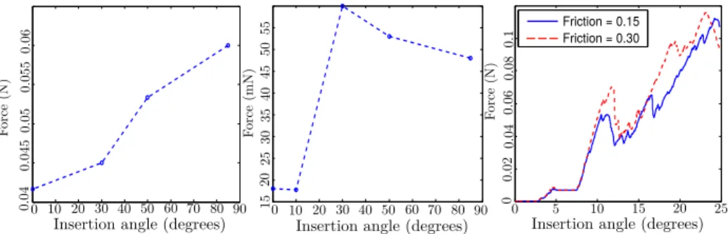
Friction = 0.15 Friction = 0.30 Force (N) Force (mN) Force (N) 0 10 20 30 40 50 60 70 80 90 0 10 20 30 40 50 60 70 80 90 00 5 10 15 20 25 0.02 0.04 0.06 0.08 0.1 0.04 0.045 0.05 0.055 0.06 15 20 25 30 35 40 45 50 55
Insertion angle (degrees) Insertion angle (degrees) Insertion angle (degrees)
Fig. 7. Forces applied on the cochlea wall (left) and the basilar membrane (center) at the first turn of the cochlea. We can see that larger forces are generated when inserting the implant at a wide angle. Regarding the forces on the basilar membrane, there are two distinct groups of angle: small angles lead to much smaller forces than wider ones. Changing the friction generally increases the forces (right). This leads to an early buckle of the implant outside the cochlea and hence to an incomplete insertion.
Acknowledgements. The authors thank the foundation “Agir pour l’audition” which funded this work and Oticon Medical.
References
1. R. Torres, G. Kazmitcheff, D. Bernardeschi, D. De Seta, J.L. Bensimon, E. Ferrary, O. Sterkers, and Y. Nguyen. Variability of the mental representation of the cochlear anatomy during cochlear implantation. Eu. Arch. of ORL, pages 1–10, 2015. 2. BK Chen, G. M Clark, and R. Jones. Evaluation of trajectories and contact
pres-sures for the straight nucleus cochlear implant electrode arraya two-dimensional application of finite element analysis. Med. engineering & physics, 2003.
3. Catherine A Todd and Fazel Naghdy. Real-time haptic modeling and simulation for prosthetic insertion. volume 73, pages 343–351, 2011.
4. Guangjian Ni, Stephen J Elliott, Mohammad Ayat, and Paul D Teal. Modelling cochlear mechanics. BioMed research international, 2014, 2014.
5. HN Kha, BK Chen, Graeme M Clark, and Rhys Jones. Stiffness properties for nu-cleus standard straight and contour electrode arrays. Medical engineering & physics, 26(8):677–685, 2004.
6. Olivier Comas, St´ephane Cotin, and Christian Duriez. A shell model for real-time
simulation of intra-ocular implant deployment. In Biomedical Simulation, pages 160–170. Springer, 2010.
7. D. Johnson and P. Willemsen. Six degree-of-freedom haptic rendering of complex polygonal models. In Haptic Interfaces for Virtual Environment and Teleoperator Systems, 2003. HAPTICS, pages 229–235. IEEE, 2003.
8. M. Tykocinski, E. Saunders, L. Cohen, C. Treaba, R. Briggs, P. Gibson, G. Clark, and R. Cowan. The contour electrode array: safety study and initial patient trials of a new perimodiolar design. Otology & neurotology, 22(1):33–41, 2001.
9. H.N. Kha and B.K. Chen. Determination of frictional conditions between electrode array and endosteum lining for use in cochlear implant models. Journal of Biome-chanics, 39(9):1752 – 1756, 2006.