Cryogenic Heat Pipe for Cooling High Temperature
Superconductors with Application to
Electromagnetic Formation Flight Satellites
by
Daniel W. Kwon
S.B. Aeronautics and Astronautics, MIT 2002
L_
S.B. Electrical Engineering and Computer Science, MIT 2002
S.M. Aeronautics and Astronautics, MIT 2005
ARCHIVES
ACHUST INS FTITFE OF TC c y
DCT
18
7'.
SUBMITTED TO THE DEPARTMENT OF AERONAUTICS AND ASTRONAUTICS
IN PARTIAL FULLFILLMENT OF THE DEGREE OF
DOCTOR OF PHILOSOPHY IN AERONAUTICS AND ASTRONAUTICS
at the
MASSACHUSETTS INSTITUTE OF TECHNOLOGY
June 2009
C Daniel W. Kwon, MMIX. All rights reserved.
The author hereby grants to MIT permission to reproduce and to distribute publicly paper and
electronic copies of this thesis document in whole or in part.
Signature of Author.
Department of Aeronautics and Astronautics
February 1, 2009
Certified by...
4/7- '00
Department of
Raymond J. Sedwick
Aerospace Engineering, University of Maryland
Thesis Advisor
C ertified by ....
...
David W. Miller
Department of Aeronautics and Astronautics
Thesis Committee Chairman
Certified by...
....
...
Accepted by...
IY
...
*
John Brisson
Department of Mechanical Engineering
...
David L. Darmofal
Department of Aeronautics and Astronautics
Chairman, Committee for Graduate Students
Cryogenic Heat Pipe for Cooling High Temperature Superconductors with Application to
Electromagnetic Formation Flight Satellites
by
Daniel W. Kwon
Submitted to the Department of Aeronautics and Astronautics on February 1, 2009 in partial fulfillment of the
requirements for the degree of
Doctor of Philosophy in Aeronautics and Astronautics in the field of Space Systems
ABSTRACT
An emerging method of propellant-less formation flight propulsion is the use of electromagnets coupled with reaction wheels. This technique is called Electromagnetic Formation Flight (EMFF). In order to create a large magnetic field necessary for actuating formation flying spacecraft, EMFF uses high temperature superconducting (HTS) wire since it is able to carry a large current at low power. To achieve superconductivity, the HTS wire needs a cryogenic thermal control system to maintain the wire temperature below the critical temperature and this temperature must be maintained over the entire EMFF coil, which could be as large as two meters in diameter. For commercially available HTS wire, this critical temperature is 110 K. Since EMFF obviates the need for consumables for formation flying maneuvers, the thermal system must also be consumable-free.
The research in this thesis investigates a consumable-free method of maintaining isothermalization for a large scale HTS coil. The HTS coil resides inside a thermally conductive jacket which is used for isothermalization. A cryocooler is attached to the thermally conductive jacket and is used for heat extraction. Wrapped around the thermally conductive jacket is multilayer insulation which is used to reduce the heat load into the HTS coil. This thermal system has the ability to maintain constant temperature in the presence of a rapidly changing thermal environment, such as low Earth orbit. Both a solid conductor and a heat pipe were investigated for use as the thermally conductive jacket. Finite difference models were developed to model a single coil in space and a coil inside a vacuum chamber. In addition, the research in this thesis investigates the design, operation, and testing of a cryogenic heat pipe. The heat pipe uses nitrogen as a working fluid and a stainless steel mesh as the wicking structure. As a proof of concept, an 86 cm long heat pipe was constructed as the thermally conductive jacket enclosing the HTS wire. The working fluid, at saturation condition, maintains a constant temperature below the HTS wire critical temperature. Testing of the heat pipe in a vacuum chamber was conducted to verify the power capacity of the heat pipe. Verifying the proof of concept cryogenic heat pipe led to construction of a full scale circular heat pipe for testing in a two meter diameter toroidal vacuum chamber. This system also achieved saturation condition and showed the potential for HTS cooling. The experiments in this thesis demonstrate the feasibility of operating large HTS coils for future formation flying missions.
Thesis Supervisor: Raymond J. Sedwick
ACKNOWLEDGEMENTS
I'd like to thank Ray Sedwick and Dave Miller for their help supporting me for many years. Their tireless
efforts are sincerely appreciated. Working for them has been a privilege and a pleasure throughout the years. I'd also like to thank John Brisson for being on my committee and providing useful feedback. Additional sources of wisdom and mentoring were provided by Edmund Kong and Alvar Saenz-Otero. I've learned a lot from everyone.
Technical assistance came from all corners. The solid foundation for any SSL project is Paul Bauer, and this research was no exception. The toroidal vacuum chamber was built by Stephan Pretorius and Payload Systems. This project alone was an amazing accomplishment. Tony Busalacchi helped provide vacuum chamber feedthroughs and assisted the heat pipe construction. Several UROPs helped with the EMFF testbed, including Amado DeHoyos, Dawn Wheeler, Kevin Liu, and Victoria Stolyar.
Sharon Brown and Marilyn Good deserve a special shout-out. Thanks for making things happen in the
SSL.
I'd like to thank members of the EMFF team throughout the years: Laila Elias, Sam Schweighart, Umair
Ahsun, Jaime Ramirez, Matt Neave, Aya Sakaguchi, Sang-il Lee and Dr. Kong. Propellant-less formation flight is not an easy topic. I think we have all done some pretty revolutionary and exciting things.
Graduate school has been a rewarding and fun time thanks to all members of the SSL. Web gem nominees go to all of those who have played and supported Aero/Astro sports. MVP awards go to the Tom McGuire, Carl Dietrich, the 2004 Red Sox, and Ryan Lang, who has raced through MIT with me since we first met in concert band over 10 years ago.
Finally, I'd like to thank my parents Hee-min and Sue and sister Sabina. Following in my parents' footsteps, I'm now proud of finishing the unwritten Kwon family rule: "get an advanced degree." But seriously, the best part of family is having a gifted and caring sibling who is making the world a better place.
Formation flying using only one satellite is a lonely business. I'd like to thank my wife Alicia for her love and support, again proving that life is better in pairs.
TABLE OF CONTENTS
Abstract...---.---...
3
Acknowledgements...-
..
...
5
Table of Contents...
7
List of Figures...
11
List of Tables...---...
15
Chapter 1
Introduction.
...
17
1.1
Current State of EMFF...
20
1.2pp
...
. 22
1.3
L iterature R eview ...
23
1.3.1
Cryogenic Systems ...
...
24
1.3.2
Related Flight Cryogenic Systems...
26
1.3.3
Review of Cryogenic Heat Pipes ...
27
1.3.4
A pplications
...
29
1.4
T hesis O utline ...
32
Chapter 2
Thermal Design....
...
....
...
.
... 33
2.1
Bulk Heat Flow for an EMFF Coil...
33
2.2
Multiple Cryocoolers ...
40
2.3
EMFF Thermal System Design Overview...
45
2.4
C hapter Sum m ary ...
49
Chapter 3
Thermal Modeling
...
51
3.1
A nalytic M odel ...
5 1
3.2
Finite Difference Model...
55
3.2.1
1D FDM Overview...
55
3.2.2
1D
FDM with Radiation...
57
3.3
Sinda M odel...
62
3.4
Model Verification with Experiment...
64
3.4.1
C opper
p
...
66
3.4.2
M LI Tests...
... -
-
-.. -... ...
68
3.5
Summary of Modeling --...
...
70
Chapter 4
HTS Heat Pipe...
...
... 71
4.1
Heat Pipe Power Capacity...
71
4.1g
...
. . 74
4.1.2g
...
. 78
4.2
Design for a Straight Heat Pipe Inside a Vacuum Chamber...
80
Table of Contents
4.2.2
Determining the Operational Power Capacity ...
82
4.2.3
Effect of Angle...
- ...
83
4.2.4
Effects of Uncertainty on the Number of Mesh Layer ...
84
4.2.5
Determining the W orking Fluid M ass ...
85
4.2.6
Temperature Model...
87
4.3
Lim itations ...
...
---... 88
4.3.1
Entrainment Limit...
89
4.3.2
Sonic Limit...
89
4.3.3
Vapor Core Diameter Limitations ...
... 90
4.3.4
Peak Heat Flux...
91
4.4
Testbed Development ...
93
4.4.1
Overview and Setup...
93
4.4.2
HTS Wire Insertion...
95
4.4.3
Heat Pipe Cleaning ...
--...
98
4.4.4
Additional Engineering Considerations...
99
4.5
Experimental Results ...--.
102
4.5.1
Test without HTS wires ...
102
4.5.2
Test with HTS Wires ...
... 106
4.5.3
Measuring the state of the HTS ...
... 112
4.5.4
Experimental Results of HTS Carrying Current...
113
4.6
Analysis of Testing ...--.
115
4.6.1
Heat Pipe Leaking...
... 115
4.6.2
Verifying Operation at an Angle...
117
4.6.3
Performance of Heat Pipe with only a Coarse Mesh ...
119
4.6.4
Maximum Current during Test ...
120
4.7
Summary of Straight Heat Pipe ...
122
Chapter 5
Circular Heat Pipe...
125
5.1
M odeling the Circular H eat Pipe ...---...
125
5.1.1
Performance without the W orking Fluid ...
... 125
5.1.2
Performance with Working Fluid ...
126
5.2
Testbed Development ...
129
5.2.1
Heat Pipe Construction ...
130
5.2.2
Liquid Nitrogen Reservoir and Working Fluid System...
131
5.3
Experimental Results ...
133
5.3.1
Model Comparison...
136
5.3.2
Tests with Additional W orking Fluid ...
... 137
5.4
Summary of Thesis Experiments...
138
Chapter 6
Conclusions...--
-..--
-
--...
...---
143
6.1
Thesis Summary...
143
6.2
Thesis Contributions...
144
Table of Contents
9
A ppendix A
H TS Torque Coils...
147
A ppendix B
A dditional Therm al D esign...
151
B. 1
M ultiple Cryocoolers ...
151
B.2
Radiator D esign ...
155
B .3
M ass of m ultiple cryocooler system ...
155
A ppendix C
A dditional Therm al M odeling ...
161
C .1
1D FD M A dditions...
161
C.2
ID Im plicit FD M ...
163
C.3
3D FD M ...
165
C.3.1
Copper
...
167
C .3.2
M LI Interior...168
C.3.3
Boundary Conditions...169
C.3.4
Interface Layers ...
173
C.4
3D A nalytic
...
174
C.5
M inim um M ean Square Error...
174
A ppendix D
H eat Pipe ...
177
D .
V apor Pressure Calculation...
177
D .2
V iscous Lim it...
177
D .3
U sing CO TS Screen M eshes...
178
D .4
Flow m eter Testing ...
182
D .5
Prototype Short Straight H eat Pipe w ith H TS ...
184
D .6
Equipm ent List...
187
D .7
Effect of w etting angle...
187
D .8
M axim um EM FF Rotation Rate ...
188
A ppendix E
Im proving H TS Perform ance ...
191
LIST OF FIGURES
Figure 1.1 Conceptual drawing of an EMFF vehicle...
18
Figure 1.2 Example of forces and torques created by two EMFF vehicles ...
19
Figure 1.3 EMFF testbed with gravity-fed LN2 reservoir (A); testbed with pressurized LN2
reserv o ir (B )...
2 0
Figure 1.4 Total mass of magnetic torquers vs. Torque in GEO for commercially available torque
rods (COTS), and HTS and Room Temperature torque coils...
30
Figure 2.1 Geometry for a single coil in the worst case heating scenario ...
34
Figure 2.2 Thermal free body diagram for coil cross-section...
34
Figure 2.3 Cross-section of a MLI blanket [57]. ...
35
Figure 2.4 Thermal conductivity of MLI versus pressure [57]...
36
Figure 2.5 MLI as a solid insulator model: Heat flow into the EMFF coils in LEO and Earth
trailin g orb it ...
37
Figure 2.6 Vacuum gap MLI model: Heat flow into an EMFF coil for a various number of
vacuum gap layers: Earth Trailing orbit and LEO cases ...
39
Figure 2.7 Sunpow er cryocooler [59]...
40
Figure 2.8 Cryocooler performance for Sunpower M87N
-
EM#1...
41
Figure 2.9 Setup for multiple cryocoolers (a) and thermal free-body diagram (b)... 42
Figure 2.10 Procedure to find total cryocooler power ...
43
Figure 2.11 Total power requirements using two cryocoolers ...
43
Figure 2.12 Outer temperature and inner cryocooler thermal load versus outer cryocooler thermal
lo ad ...
4 4
Figure 2.13 Minimum total power for two cryocoolers vs. the cryocooler cold tip temperature. 45
Figure 2.14 Design of EMFF HTS coil thermal system with a single cryocooler... 47
Figure 3.1 Coil geometry for the ID analytic model with a cryocooler at the origin... 52
Figure 3.2 Results of ID analysis showing large temperature rise away from the cryocooler at x
=0 ...--...
5 3
Figure 3.3 Summary of finite differencing procedure for ID...
56
Figure 3.4 Comparing temperature as a function of distance along the TCJ for the ID FDM and
ID analysis (w ith no radiation) cases ...
57
Figure 3.5 Temperature distribution in TCJ in vacuum chamber ...
59
Figure 3.6 Thermal load in TCJ in vacuum chamber as a function of time ...
60
Figure 3.7 Temperature distribution in TCJ in space model ...
61
Figure 3.8 Thermal load in TCJ in space model as a function of time ...
62
Figure 3.9 Sinda m odel (ID ) for coil...
63
Figure 3.10 Comparison between Sinda and finite difference models showing temperature
increase with distance away from the cryocooler (at x = 0)...
64
Figure 3.11 Experimental vacuum chamber (closed)...
65
Figure 3.12 Experimental vacuum chamber (opened) with copper thermally conductive jacket 65
Figure 3.13 Liquid nitrogen cooling loops around copper test article...
66
Figure 3.14 Comparing transient temperature of experiment (dots) with FDM (solid lines of same
co lo r) ...---..---...
6 7
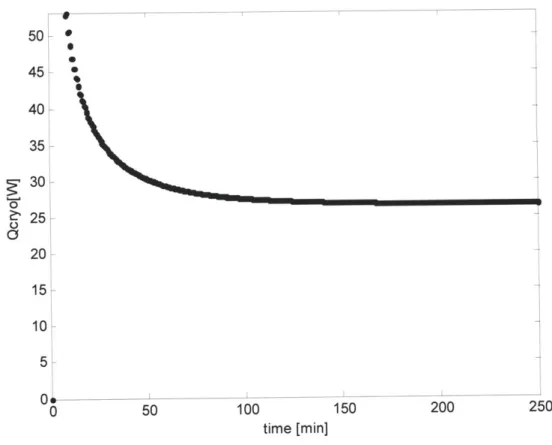
Figure 3.15 Temperature and thermal load of TCJ after 140 minutes...
67
Figure 3.16 Copper jacket wrapped in MLI...
69
List of Figures
12
Figure 4.1 Basic operation of a heat pipe ...
72
Figure 4.2 Sketch of wick and pore parameters (not to scale)...
72
Figure 4.3 Pore radius vs. m esh num ber...
76
Figure 4.4 Heat pipe power vs. pipe diameter using #100 and #250 wire mesh screens for a 1 m
length pipe...---
..
---...
77
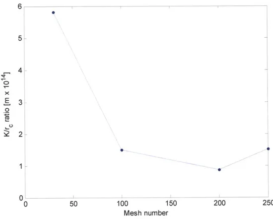
Figure 4.5 Ratio of permeability to pore radius versus mesh number ...
78
Figure 4.6 HTS wire stack inside a heat pipe ...
79
Figure 4.7 Heat pipe design for a #100 inner mesh, #250 outer mesh (2 layers each), 1 m pipe. 79
Figure 4.8 Heat pipe designs using 2 layers of either a #30 or #100 inner mesh layer; #250 outer
m esh (2 layers)...
.. ---... 80
Figure 4.9 Therm ocouple locations on pipe ...
81
Figure 4.10 Temperature for heat pipe with no working fluid ...
82
Figure 4.11 Heat pipe design using 2.4 layers of a #30, #50, or #100 inner mesh, 2 layers of a
#250 outer m esh ...-
.
---... 83
Figure 4.12 Heat pipe power capacity versus angle of evaporator above the condenser for various
length pipes ...---...
84
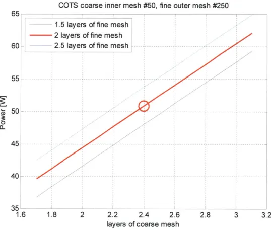
Figure 4.13 Varying the number of coarse mesh (#50) layers with 1.5, 2, and 2.5 layers of fine
#250 m esh ...---...
. . ---... 85
Figure 4.14 Mass of working fluid as a function of inner coarse mesh...
86
Figure 4.15 Heat pipe modeled as a resistive network ...
87
Figure 4.16 Vapor space limitations imposed by HTS stack...
91
Figure 4.17 Peak heat flux for condenser as a function of condenser length for straight heat pipe
...
9...92
Figure 4.18 Heat pipe setup in vacuum chamber...
94
Figure 4.19 Heat pipe and liquid nitrogen reservoir ...
94
Figure 4.20 W orking fluid injection setup...
95
Figure 4.21 Power resistor and HTS wire connectors on the heat pipe...
96
Figure 4.22 Heat pipe with aluminum block and HTS wires ...
96
Figure 4.23 Minimum size of LN2 reservoir pipes given the required heat load... 101
Figure 4.24 Thermocouple locations for test without HTS wire ...
103
Figure 4.25 Test of heat pipe without HTS wire showing working fluid mass, resistor power and
tem perature of the pipe as a function of tim e ...
103
Figure 4.26 Temperature vs. axial distance from the condenser for various values of applied
pow er...---...
105
Figure 4.27 Temperature at end vs. total power input ...
106
Figure 4.28 Thermocouple locations for tests with HTS wire...
107
Figure 4.29 Test of heat pipe with HTS wire...
108
Figure 4.30 Pressure in the heat pipe (top) and the vacuum chamber (bottom) during testing.. 109
Figure 4.31 Temperature vs. axial distance from the condenser for various amounts of total
pow er...-
- .
---... 110
Figure 4.32 Normalized difference in experimental and modeled evaporator temperature for test
w ith H T S ...---...
. ---...--
- -- -111
Figure 4.33 Normalized difference in experimental and modeled evaporator temperature for tests
w ith and w ithout HTS...----...-
- ... 111
List of Figures
13
Figure 4.35 Experimental results for a heat pipe with HTS carrying current... 114
Figure 4.36 Working fluid mass during a test comparing total measured mass and post-processed
m ass accounting for leaking...
115
Figure 4.37 Geometry of gap size due to thermal coefficient mismatch...
116
Figure 4.38 Geometry of a 'pipe' at an angle showing the liquid level if pooling occurs... 118
Figure 4.39 Heat pipe power capacity for a system with only coarse mesh...
119
Figure 4.40 Variation of HTS critical current density with temperature and magnetic field
parallel (a) and perpendicular (b) to the HTS wire [8] ...
120
Figure 4.41 Variation of HTS critical current density with temperature, no self field... 121
Figure 4.42 Temperature vs. time for a test with HTS wire (a) and corresponding theoretical
m axim um current vs. tim e (b)...
122
Figure 5.1 Temperature vs. distance away from the condenser for heat pipe without working
flu id ...
12 6
Figure 5.2 Heat pipe power capacity of various numbers of inner mesh and outer mesh layers 127
Figure 5.3 W orking fluid m ass ...
128
Figure 5.4 Toroidal vacuum chamber with heat pipe ...
130
Figure 5.5 Procedure to insert mesh into pipe sections ...
131
Figure 5.6 Liquid nitrogen reservoir for circular heat pipe ...
132
Figure 5.7 Working fluid fill system for circular heat pipe ...
132
Figure 5.8 Testing a circular EMFF heat pipe showing working fluid mass, resistor power and
tem perature ...
. . ...
134
Figure 5.9 Pressure in heat pipe (top) and vacuum chamber (bottom) during testing... 135
Figure 5.10 Temperature around heat pipe for various amounts of power from resistor... 136
Figure 5.11 Comparing normalized difference between experimental data and resistive network
model for temperature at the end of the evaporator...
137
Figure 5.12 Tem perature vs. heat pipe power...
138
Figure 5.13 Transient temperatures for Heat pipe with working fluid, HP without working fluid,
and HP w ithout w orking fluid w ith M LI...
139
Figure 5.14 Temperature vs. axial distance from the condenser for heat pipe, heat pipe without
working fluid and heat pipe without working fluid with MLI...
140
Figure A. 1 Total mass of magnetic torquer versus torque, for HTS and room temperature copper
coils, 1 m radius, and COTS torque rods for a satellite in LEO (a), in GEO (b)... 148
Figure A.2 Component masses for the HTS and RT torque coils. ...
149
Figure B. 1 Thermal free body diagram for multiple vacuum gaps with multiple cryocoolers .. 151
Figure B.2 Results for a uniformly cooled system ...
153
Figure B.3 Results with cooling located close to the coil...
154
Figure B.4 Results with cooling located close to the outer layer...
155
Figure B.5 Mass of thermal system for a single stage and two stage system... 157
Figure B.6 Mass of a system using a gas reservoir...
159
Figure B.7 Mass of a single stage thermal system...
159
Figure C. 1 Volumetric heat capacity vs. temperature relative to room temperature values... 163
Figure C.2 Thermal diffusivity vs. temperature relative to room temperature values... 163
Figure C.3 Temperature distribution for the implicit FDM...
165
Figure C.4 Finite difference regions for 3D FDM...
166
List of Figures
14
Figure D. 1 Pore radius for various mesh number ...
179
Figure D.2 Void fraction and permeability for various COTS mesh numbers...
179
Figure D.3 Ratio of permeability to pore radius for COTS mesh...
180
Figure D.4 Single mesh heat pipe, 4 layers, using COTS mesh, 1 m length, 40 mm diameter.. 181
Figure D .5 Flowm eter algorithm flowchart...
183
Figure D.6 Flowm eter calibration with CO
2gas ...
184
Figure D.7 Prototype copper pipe with HTS wires inside aluminum block...
185
Figure D.8 Temperature near HTS wires while soldering on copper pipe cap...
186
Figure D.9 Change in capillary pressure as a function of wetting angle\...
188
Figure D. 10 Sketch of the effects of a rotation for an EMFF coil...
189
Figure D. 11 Maximum allowable rotation rate for EMFF vehicle as a function of mesh number
...
190
Figure E. 1 G eom etry of H TS coil turns...
192
Figure E.2 HTS wire stacks for the MIT-SSL EMFF testbed ...
192
Figure E.3 Toroidal stack design ...
. . .... 193
LIST OF TABLES
Table 2.1 Variables used in thermal analysis...
38
Table 2.2 Sunpower cryocooler specifications [59] ...
40
Table 2.3 Condition at minimum total power condition...
44
Table 2.4 Plan for current approach ...
48
Table 3.1 Parameters for 1D analysis ...
54
Table 4.1 Properties of Nitrogen at saturation conditions (77 K, 1 atm)...
74
Table 4.2 W ire m esh properties...
75
Table 4.3 Heat pipe design summary...
93
Table 4.4 Nitrogen saturation pressures at various temperatures ...
99
Table 4.5 Non-superconducting resistances measured by Wheatstone bridge ... 113
Table 4.6 Height of liquid level given mass of working fluid ...
119
Table 5.1 Summary of EMFF circular heat pipe ...
129
Table B.1 Mass of heat pipe for a 1 m coil...
156
Table B.2 Mass of gas reservoir for a 1 m coil...
158
Table C. 1 Computational time comparison between different modeling schemes ... 165
Table C.2 . and MSE for the copper TCJ without MLI...
175
Table C.3 et and MSE for the circular heat pipe ...
175
Table D. 1 Testing the flowmeter accuracy by filling the circular heat pipe with air at various
p ressu res...-
- - - ... ---...
183
Chapter 1 Introduction
An increasing number of missions are considering multiple spacecraft flying in close proximity to replace traditional large monolithic space systems. Formation flying space interferometers are one example of this application. NASA's Terrestrial Planet Finder Interferometer and ESA's Darwin mission have the goal of directly detecting Earth-like planets in other solar systems. Both systems utilize multiple free-flying satellites in formation to perform as a nulling interferometer [1, 2]. A second example of the concept of replacing a large satellite with smaller entities is used by Darpa in their F6 program. The F6 program stands for Future, Flexible, Fast, Fractionated, Free-Flying Spacecraft united by Information eXchange [3]. F6 plans to demonstrate that a large satellite can be divided up into separate functional modules, whereby the new fractionated spacecraft has benefits such as launch flexibility, improved robustness from failures or attacks, and improved upgradeability.
One of the challenges for formation flying systems is that the amount of propellant available puts a constraint on mission lifetime and AV capabilities. An emerging method of propellant-less formation flight propulsion is the use of electromagnets coupled with reaction wheels. This technique is called Electromagnetic Formation Flight (EMFF). The system is powered by the Sun through solar arrays, meaning a satellite is no longer reliant on propellant for formation flying maneuvers. Reducing a satellite's dependence on propellant can change current design methods for future spacecraft formations. For example, the amount of propellant required is currently determined using the rocket equation and typically the AV required for formation flying is a parameter used in the calculation. For propellant-based
systems, one method of minimizing propellant mass is to reduce the formation flying AV. Since EMFF is propellant-less, the rocket equation is not used. Therefore, by using EMFF, the formation flight propulsion system can be based on the desired formation performance, without any fuel constraints. As a result, EMFF opens up new capabilities for satellite formations that might have had AV requirements that before were too costly in terms of propellant to even consider. Another advantage of EMFF over traditional propellant-based thrusters is the elimination of impinging thruster plumes, which can cause ablation of nearby spacecraft surfaces and produce unwanted vibration excitation [4]. Applications of EMFF are not just restricted to stationkeeping fractionated spacecraft architectures or maintaining sparse aperture systems. The Electromagnetic (EM) coils can be used with multi-role functionality, such as power transmission, torque for slew control, or for passive offensive or defensive capabilities in military satellites [5, 6].
Chaoter 1 - Introduction
To implement EMFF, an EM dipole is created by running current through an electromagnetic coil. A conceptual drawing of an EMFF vehicle is shown in Figure 1.1. The EM dipole creates coupled forces and torques on nearby satellites which also have at least one EMFF coil. A satellite with three orthogonal coils can create a steerable dipole in three dimensions. Similarly, a set of three orthogonal reaction wheels are necessary to de-couple the forces and torques in three dimensions. Consequently, the EM coils in concert with reaction wheels allow for all the necessary actuation in relative degrees of freedom for a formation flight array [7]. An example of the forces and torques created by two EMFF vehicles are shown in Figure 1.2.
Figure 1.1 Conceptual drawing of an EMFF vehicle
The force between two vehicles with their dipole orientations axially aligned, such as in a repulsion configuration shown in Figure 1.2, is given by
F = 3
pA/2)r
d
(1.1)where d is the separation distance between the vehicles and pX is the permeability of free space. The magnetic dipole for each vehicle is p and is a function of the current (i), number of current loops (n), and the radius of the coil (Re):
p = nirrR (1.2)
In order to create a large magnetic moment to generate large forces, coils that can carry a large current and are large in size are favorable for EMFF.
Chanter 1 - Introduction
Figure 1.2 Example of forces and torques created by two EMFF vehicles
The high temperature superconducting (HTS) wire is an enabling technology for EMFF because it allows the creation of a large dipole moment. One of the challenges of using HTS is maintaining the cold temperature necessary for operation. The entire length of the superconducting wire must be maintained below a critical temperature in order for it to operate at superconducting levels. Commercial-off-the-shelf
(COTS) wire from American Superconductor has a critical temperature, Teincai, of 110 K [8]. For EMFF satellites in the proximity of Earth, such as LEO or GEO, heat flux from the Sun and Earth needs to be rejected in order to maintain temperatures below Tc, teai. This heat flux has the potential to rapidly change in both magnitude and direction, depending on the satellites' orientation. Heat into the coils can be rejected using cryocoolers and various types of insulation such as Multilayer Insulation (MLI). One characteristic of the HTS wire is that at colder temperatures more current can be driven through the wires creating a larger dipole field and thus improving the performance of EMFF. However, this benefit comes at the expense of additional power and mass required by the thermal system. In addition to this coupled behavior, the thermal system must also be consumable-free since EMFF obviates the need for consumables for formation flying maneuvers. The EMFF thermal system is a unique problem in the topic of cooling large space structures without the use of consumables.
Chaner 1- Inrodution20
1.1
Current State of EMFF
In order to develop the necessary technology for EMFF, development of a ground EMFF testbed by the MIT Space Systems Laboratory (MIT-SSL) started in 2002 by an undergraduate design and build course. Two EMFF testbed vehicles were built, each with two coils allowing for a steerable dipole in two dimensions. The coils were made from Bi-2223 HTS wires from American Superconductor and have a diameter of approximately 80 cm. The EMFF testbed used a reservoir of liquid nitrogen (LN2) to cool the HTS coils. This first version of the EMFF testbed, built by the undergraduate course, used a
gravity-fed LN2 reservoir and is shown in Figure 1.3a.
Liquid Nitrogen Tank HTS coils in containment eaction heel Motor Metrology Reaction
vionics & wheel
Power Boards
LN2 tank
Air Gas
tank--Air
Carriage suppy
Base &-Gas carriage,
A)
B)
Figure 1.3 EMFF testbed with gravity-fed LN2 reservoir (A); testbed with pressurized LN2 reservoir (B)
For the first version of the testbed the source of cryogen was located above the HTS coil and flowed into the coil container replacing any boiloff. There were two problems with the design. First, the boiloff and liquid cryogen shared the same flow path making it difficult to determine how much liquid cryogen was actually inside the coil container cooling the HTS. Secondly, thermal cycling of the coil container led to cracking in the Styrofoam containment material and epoxy joints. Improvements to the thermal system were implemented in the second version of the EMFF testbed built by Kwon and Neave and is shown in Figure 1.3b [5, 9]. A coil container made of copper housed the HTS coils and contained the liquid
nitrogen. A pressurized LN2 tank fed the LN2 from the bottom of the coils and maintained cryogen
... :: ... .... . I I., I .. ... .
Chapter 1 - Introduction 21
throughout the entire coil. Excess LN2 and boiloff were vented from the top of the vehicle via chimneys. The new thermal design on the testbed has allowed for the amount of cryogen in the system to be more accurately determined and has eliminated any problems associated with leaking cryogen.
Past research on a flight version of the thermal system determined that a cryocooler was necessary for heat extraction and COTS cryocoolers had the ability to extract the tens of watts necessary for steady-state cooling. In addition, a comparison of insulation systems consisting of a vacuum gap or aerogel was conducted in both LEO and in Earth-trailing orbit, which is outside of the Earth's heating environment. A quick summary of these details will also be discussed in Chapter 2.
In addition to developing the EMFF thermal system there are several other challenges to bringing EMFF to a flight-like state. These include the power system, magnetic shielding, and dynamics and control. The power system for EMFF supplies the high current for the HTS wires. A high current, low voltage and low power H-bridge design for the power circuit has been demonstrated on the EMFF testbed using
COTS electronics components. The re-built EMFF testbed uses three D-cell batteries to supply 100 amps
to a coil and the entire power system for two coils requires less than 100 Watts.
A large part of the EMFF research conducted by the MIT-SSL has been the dynamics and control of
EMFF satellites. Control of EMFF satellites is challenging because of the coupled nature of the electromagnetics and the non-linearity of the EM force with distance. In LEO, the dynamics and control of an EMFF satellite are affected by the variation in the magnetic field and the J2 perturbation [10]. Non-linear controllers operating in real-time have the potential to burden the avionics system. Past research has investigated the dynamics and control for EMFF arrays in LEO and experimentally validated linear control techniques on the testbed [7]. Current EMFF research at MIT also includes examining control of n-vehicle arrays, non-linear controllers on the testbed, and use of smaller scale EMFF coils using conventional conductors for microsatellites [11, 12].
A concern that is commonly asked about EMFF is the effect the magnetic fields have on electronics.
Kwon investigated the effect of the testbed coils on GPS avionics [5]. It was determined that the maximum field strength of the testbed, approximately 50 Gauss, did not affect the signal strength received
by the GPS antenna and receiver. However, the effect of larger flight sized coils operating at possibly
higher field strengths is unknown. To shield the avionics it has been suggested to enclose any sensitive electronic equipment in a box made of mu-metal to act as a sort of magnetic Faraday cage.
A group in Japan at the University of Tokyo and JAXA has also been independently researching the
EMFF concept. The Japanese team has performed preliminary trade studies and dynamics and control simulations for two EMFF satellites in LEO [13]. In addition, a group at the Polish Academy of Sciences
Chapter 1 - Introduction
extended the two vehicle non-linear controller developed by Elias to a three vehicle linear array and a three vehicle triangular array [7, 14]. A sister technology to EMFF that has been investigated by
Michigan Technological University is the use of Coulomb forces from charged spacecraft for formation flight propulsion [15]. Unfortunately this system is not capable of producing spacecraft torques or shear motions, degrees of freedom that are achievable using EMFF. The EMFF testbed at the MIT-SSL is the only known testbed for propellant-less formation flying using electromagnetics.
1.2
Research Objectives and Approach
The goal of this thesis is to develop a renewable method of cooling large space structures, such as the
HTS coils used for EMFF, which can maintain uniform cryogenic temperatures across large
one-dimensional structures operating in orbits where the thermal environment is characterized by time varying sources with substantial heat flux, such as Earth IR and solar reflection and eclipse. There are three challenges of this problem statement that are important.
First, a renewable method of cooling means that the thermal design must not be reliant on consumables, such as onboard cryogens. Both the method of extracting heat from the system and the distribution of heat should be consumable-free. On the testbed, the coils are immersed in a bath of liquid nitrogen to maintain a continuous temperature of 77 K. Liquid nitrogen is used on the testbed because it operates in a room temperature, one atmosphere environment where conduction and gravity-induced convection make thermal control a challenge. EMFF in LEO will face a high thermal flux environment, but the vacuum allows for other thermal management techniques such as MLI, heat pipes, and cryocoolers. More importantly, the use of liquid nitrogen on the testbed is not trace-able to a flight design because the liquid
nitrogen is a consumable. Since one of the benefits of EMFF is to replace consumables the design of the
thermal system must be self-contained. An active cooling system, such as a cryocooler, powered by solar arrays meets the requirements for a heat extraction method.
The second challenge of the problem is the scale of the thermal design since the HTS coils potentially can be as large as two meters in diameter. This eliminates devices intended for cooling concentrated point heat sources, such as detectors on space telescopes, and focuses the problem on distributed cooling techniques. It is important to maintain isothermalization of the coil, meaning that minimal temperature gradients exist across the entire coil because the warmest point in the coil will limit the performance of the HTS wire. The research in this thesis investigates locating the HTS wire inside a cryogenic heat pipe as a means of maintaining isothermalization. The research will also compare the performance of a cryogenic heat pipe with other consumable-free designs such as a solid conductor.
Chapter 1 - Introduction 23
The third challenge of keeping the EMFF HTS coils at cryogenic temperatures is the constantly changing heating environment in Earth orbit. Because of the rapidly changing orientation of the vehicles heat from the Earth and Sun are not constant with respect to time or direction. For this reason sun shields are not practical for EMFF.
In summary, the objective of the research is to develop a flight-like design for an EMFF spacecraft concentrating on the implementation of the consumable-free cryogenic thermal control of the HTS coils. The core hypothesis of the thesis is that a consumable-free method of maintaining cryogenic temperatures for a large scale HTS coil that is independent of orbit exists using a cryogenic heat pipe, by which isothermalization of the coil is maintained by locating the HTS wire inside the vapor space of the heat pipe.
To accomplish the research objective the first task is to understand the scale of the thermal problem by developing simulation models. Insight can be gained by modeling a solid conductor with and without MLI to determine temperature performance of a system without working fluid, the effect of insulation, and the amount of heat into the system. In order to gain confidence in the simulation models, experimental testing is conducted. Also by testing in a vacuum chamber environment that has a heat flux greater than low Earth orbit gives confidence that the system will work in space. To determine the benefits of operating a system with working fluid, a heat pipe is designed and constructed. First, a proof-of-concept straight heat pipe is built to verify modeling and master the manufacturing process. Next,
HTS wire is inserted into the straight heat pipe to demonstrate the ability of the thermal design to cool HTS. Finally, a circular heat pipe is designed and built to demonstrate the ability to cool a large scale HTS coil. Once the cooling methods, heat distribution, and heat rejection methods are modeled and
experimentally verified, the thermal design can be migrated to a flight version with high confidence.
1.3
Literature Review
EMFF is just one application where superconducting wire was found to be an enabling technology. MRI machines in hospitals, particle accelerators, interplanetary propulsion concepts such as the VASIMR [16], nuclear fusion experiments, and future electrical power transmission systems all incorporate superconducting wires. Superconducting technology allows the ability to create large magnetic fields and carry high currents all without any cost in wire resistance. Of course, the cost of using superconductors is the cryogenic system necessary to allow materials into a superconducting state. The subject of cryogenics
is best summarized by Dr. Steven Van Sciver of the National High Magnetic Field Laboratory [17]: "Cryogenics is a necessary but often undesirable part of a superconducting system because it increases cost, reduces reliability, and increases complexity."
Chapter 1 - Introduction
The task of the thermal design in this thesis, and in any superconducting system, is to minimize the costs incurred by the cryogenic system so that the full benefits of using superconducting wire can be realized.
1.3.1 Cryogenic Systems
Superconducting devices need refrigeration to overcome two sources of heat loading. The first is any heat leaking into the system from the surrounding environment. The second is any internal heat generation in the device. This could be from non-superconducting splices, leads, or AC losses [18]. AC losses are the result of induced time-varying electric fields in the normal-state regions of HTS wires, which lead to the occurrence of Joule dissipation. The varying electric field is caused by a time-varying magnetic field, which is the result of a time-time-varying current through the wire. In addition, a refrigeration device is needed to bring the superconductor from ambient to low temperature in a reasonable length of time. Currently, there are three main methods for cooling a superconducting magnet. The most common method is immersing the magnet in a liquid cryogen by which heat is extracted by evaporation of the liquid. A common method of achieving an isothermal bath is to use liquid nitrogen or liquid Helium (LHe). Selection of a cryogen depends on the required operating temperature. Early high field metallic superconductors such as NbTi (Tce= 9 K) used LHe, which has a normal boiling point
(NBP) of 4.2 K [17]. Recent developments of HTS wire allows the use of LN2 (NBP = 77 K), which is significantly cheaper than LHe. A limitation of using cryogens is that they have a narrow operating temperature which is restricted by the cost and suitability of available cryogens. More importantly, for space applications, the amount of cryogen available limits the lifetime of the superconducting device. Once the cryogen has evaporated it must be replenished making it a mission life limiting consumable. A common example of bath cooling is MRI magnets in hospitals and research facilities. MRI machines have very little evidence of cryogenics and typically only require annual service to top off liquid cryogen. The second method for cooling superconducting magnets is to integrate the magnet with a closed cycle refrigeration system or cryocooler to circulate the cryogen to the magnet. This method is similar to bath cooling because the magnet is also 'wet', meaning that it is in direct contact with a liquid cryogen surrounding the magnet containment vessel. Heat is removed at a liquefier or refrigerator located outside the magnet vessel. The difference with bath cooling is that there is a refrigeration cycle that recovers the vapor and returns liquid to the magnet. A common example is the recuperative Collins refrigeration cycle, which uses a steady flow of Helium through refrigerator components, such as a compressor, heat exchangers, and expansion engines, to deliver liquid cryogen to the magnet [17]. Types of cryocoolers that have been used in these superconducting systems include pulse tube refrigerators, Gifford-McMahon cryocoolers, Stirling coolers, and Joule-Thomson coolers [19, 20]. Examples of closed cycle refrigeration systems are seen in high energy particle accelerator laboratories and nuclear fusion experiments. The
Chapter 1 - Introduction 25
disadvantages of using a closed cycle refrigeration system are that they can be capital intensive and require considerable technical support [17].
The third method for cooling superconducting magnets is conduction cooling a magnet in direct contact with a cryocooler, which extracts heat. In this method the magnet is 'dry' or cryogen-free. Cryogen-free magnets are an emerging method because of advances in cryocooler technology and the development of high temperature superconducting current leads. Dry magnets are beneficial because they are free of consumables, easy to operate and maintain, and make the magnet's cryogenic system less visible [18]. There are numerous challenges to designing a dry magnet system. The magnet must be extremely well insulated, which can potentially limit the size, operating current, and cool down time. In addition, dry magnets are inherently unstable due to the small heat capacity at low temperatures, especially for low temperature superconductors (LTS). There is no thermal storage capacity to allow for continued operation if the cryocooler fails. Reliability can be increased using multiple components, such as cold heads or compressors, but this solution takes up time, mass, and power. Therefore dry magnets must be very careful to minimize AC loss or other thermal disturbances that might induce quench. A quench is the process of a superconducting coil entering the normal or resistive state and can lead to rapid loss of superconductivity. Kopera designed an example of a small HTS magnet cooled by a single-stage cryocooler [21]. The magnet used HTS tapes based on the Bi-2223 material, which are similar to the EMFF testbed HTS wires. However, the magnet size is considerably smaller; its magnets were HTS "pancake" coils with a 5 cm inner diameter, and a 9.8 cm outer diameter.
There are also emerging hybrid methods of cooling. An example is MRI machines that use a cryocooler to recondense LHe boiloff [17]. Also some dry LTS magnets have used a small liquid Helium reservoir to increase thermal stability [22].
The thermal system in this thesis is a new type of hybrid approach. It uses a cryocooler to extract heat and a cryogenic heat pipe as the magnet vessel. Inside the magnet vessel, the HTS wire is not 'wet' since it is not in a bath of cryogen, but it is also not 'dry' since it is not conduction cooled. Instead it is vapor cooled by the working fluid. In addition, circulation of the working fluid or cryogen occurs passively inside the heat pipe, which is different from some closed refrigeration systems. There are several benefits to the hybrid system in this thesis. First, by using a cryocooler the lifetime of the system is not limited by stored cryogens. This is an advantage over bath cooling, which was the first method for cooling superconducting magnets discussed in this section. Second, the distribution of working fluid inside the heat pipe occurs passively and requires no active mechanical process or moving parts. This system is easier to maintain in space and is a benefit over the second method mentioned in this section. Lastly, the working fluid increases the thermal storage capacity of the entire cryogenic magnet system and avoids the
Chapter 1 - Introduction
thermal stability problems of purely 'dry' magnets, which were part of the third method. In summary, the hybrid approach is able to avoid limitations of each of the three conventional methods of cooling superconductors.
1.3.2 Related Flight Cryogenic Systems
Current and future space missions such as space telescopes and particle detectors require cryogenic components to cool devices. The Spitzer space telescope has a cryostat for its detector instruments. The cryogen tank contains 360 liters of superfluid Helium and has an expected lifetime of five years [23]. Past Helium cooled payloads include the Infrared Astronomical Satellite (IRAS) in 1983, Cosmic Background Explorer (COBE) in 1989, Superfluid Helium On-Orbit Transfer Flight Demonstration
(SHOOT) in 1993, and the Infrared Space Observatory (ISO) in 1995 [24]. These missions had inventories of Helium as large as 2,300 L. The future Alpha Magnetic Spectrometer (AMS-02) experiment plans to have a He inventory of 2,500 L and is launched cold [24]. The James Webb Space Telescope (JWST) uses a deployable spacecraft sun shield to block heat from the Sun, Earth, and Moon
[25]. In order to reduce the heat load, the planned orbit for JWST is ESL2, the second Lagrange point of
the Earth-Sun system. Sun shields are a passive method of cooling devices in space, but there are also some disadvantages. Since the telescope is thermally 'open' there are straylight issues from two sources. There is light from celestial sources outside the field of view and thermal emission of the telescope and surrounding surfaces which can enter the detector [26]. While many space observatories demonstrate operation of cryogenic systems in space, many rely on consumables and JWST's system relies on a specific orbit. Therefore no current or future mission contains complete cryogenic thermal control systems that are applicable to EMFF operating Earth orbit. However, there are some various component technologies that are useful.
The main components of the EMFF HTS thermal system include the cryocooler and a cryogenic heat pipe. One benefit of these various cryogenic cooling technologies is that they have been demonstrated in space. An example of a cryocooler is one that has flown on the Hubble Space Telescope as part of the Creare NICMOS Cooling System [27]. In addition, Sunpower Inc. has flown their M77 cryocooler on the RHESSI mission in 2002 and Ball Aerospace flew a Joule-Thomson cryocooler on STS-85 in 1997 [28]. The Sunpower M87N Stirling cryocoolers will also be used on the AMS-02 experiment onboard the International Space Station. The cryocoolers are used to cool the outermost vapor cooled shields to extend the life of the stored cryogen. It will be the first space flight mission with Stirling-cycle cryocoolers operating with a substantial steady-state magnetic field. Ground tests have been conducted demonstrating the feasibility of operating the cryocooler in fields as high as 925 Gauss [29], which is over twenty times the field of the MIT-SSL EMFF ground testbed. JWST also plans to use a cryocooler. The
Chapter 1 - Introduction 27
interesting aspect of JWST's pulse tube cryocooler is that the cold head is located approximately 20 meters away from its compressor and the cryocooler electronics [25]. This is one example of cryogenic components operating at long distances. JWST is an example of a future large space structure operating at cryogenic temperatures. Using a sun shield, the entire optical telescope assembly, including a six meter primary, secondary support tower and secondary mirror, will operate at around 40 K.
An example of a current large space structure operating at cryogenic temperatures is the Copernicus
OAO-3 (Orbiting Astronomical Observatory) satellite. The satellite consisted of a 80 cm UV telescope
which operated at steady-state cryogenic temperatures using a sun shield and heat pipes. No active cooling was used in Copernicus [30]. Also demonstrated on the shuttle was a cryogenic heat pipe (CRYOHP) on STS-53 in December 1992, which operated between 60 to 140 K [31]. More details on cryogenic heat pipes are given in the next section. Because of their flight heritage, cryocoolers and cryogenic heat pipes are promising technologies for the EMFF thermal system.
In this section, examples of a large scale cryogenic system have been shown by JWST and OAO. Consumable-free or passive methods of cooling using sun shields or cryocoolers powered by the Sun have also been presented. Some of the missions have specific orbits, such as JWST, others reside inside the shirtsleeve environment of the space shuttle or ISS. Cooling HTS coils for EMFF combines all of these challenges since a design that is large scale, consumable-free and independent of orbit is needed.
1.3.3 Review of Cryogenic Heat Pipes
A heat pipe is a device used to transport heat from one location to another. Heat pipes work using two
phase flow properties of a working fluid and in doing so act like a material with very high thermal conductivity. The length of the pipe is the effective distance that heat is transported. There are two characteristic 'diameters' used to describe the size of a heat pipe in this thesis. For a circular heat pipe in the shape of a coil, its size will be referred to as the coil diameter or simply diameter. Most heat pipes have a circular sectional area. This dimension will be referred to as the pipe diameter or cross-sectional diameter. For a typical heat pipe the pipe length is much larger than the pipe diameter.
The first heat pipes were built at Los Alamos National Laboratory in the 1960s by Grover [32]. Work on cryogenic heat pipes began soon after; one example is a nitrogen heat pipe developed at MIT by Silvares and Cravalho in 1973 [33]. The MIT cryogenic heat pipe used a grooved wick structure constructed from metallic fins and was 12 inches long with a 7/8 inch pipe diameter. It was designed for 309 Watts, but experimentally demonstrated a power capacity of 60 Watts. The first test to demonstrate a cryogenic heat pipe in microgravity was conducted onboard a sounding rocket in 1975 by Harwell [34]. This heat pipe used methane as a working fluid, axial grooves as a wick and was 76 cm long with a 1.58 cm outer pipe
Chaoter 1 - Introduction
diameter. Tests demonstrated operation of the heat pipe during the six minutes of microgravity. Ground heat pipes are one of the earliest examples of large scale heat pipes. During the 1970s, the 'cryo-anchor' program in the Alaskan tundra consisted of heat pipes as large as 18 m in length and 7.5 cm in
cross-sectional diameter that were placed in the ground for permafrost preservation [35].
While the concept of using a heat pipe for isothermalization of a large superconducting coil in space is novel, there is heritage for the use of heat pipes in space. Heat pipes have been used within a solar array, connecting opposite faces of the solar array to minimize thermal gradients; one side of the heat pipe located on the cell side facing the Sun, while the other end was on the radiators. Previously it was mentioned that heat pipes were used on OAO in the early 1970s to control thermal gradients of optical surfaces. The highly conductive properties of a heat pipe are used to eliminate structural distortions. Heat pipes have also been proposed as a method for structural isothermalization for the National Space Observatory and the Space Shuttle [35] and to remove heat from infrared detectors and the aperture shroud for satellite infrared systems [36].
There have been additional ground developments related to components of the EMFF thermal system. Daugherty has developed a nitrogen pipe to conductively cool HTS current leads [37]. Prenger used nitrogen heat pipes as a thermal shunt between two stages of a Gifford-McMahon cryocooler [38].
All of the flight cryogenic heat pipes discussed have been either small in cross-sectional diameter, short in
length, or both. Based on the size of the EMFF testbed HTS wire stacks, the resulting cross-sectional diameter of a heat pipe containing stacks of HTS wires must be four centimeters or greater. In addition, the heat pipe must be circular to contain the coil. While the coil diameter for the EMFF testbed is approximately 80 cm, flight EMFF coils have been envisioned with diameters of two meters and larger
[5]. It is important to note that the length of the heat pipes is determined by the coil's circumference. The
heat pipe with the closest scale to this is the CRYOHP onboard the shuttle, which had one to two centimeter cross-sectional diameter heat pipes with effective lengths on the order of 114 cm [31].
There are several challenges to developing cryogenic heat pipes compared to ambient or high temperature heat pipes. In general, the performance of cryogenic working fluids can be limiting because of their low surface tension and heat of vaporization. The working fluid also exhibits high pressures when the pipe is at ambient conditions. This means that wall materials, wall thickness, welding and sealing of cryogenic pipes are very important to avoid leakage and bursting. One alternative to this is to use an excess volume reservoir or a liquid trap at the evaporator [39]. Various lessons learned from previous research have been considered for this thesis. Kreeb tried several mesh types such as open grooves, screen covered grooves and different layers of screen, and determined that screen covered grooves allowed for the most amount of heat transfer [40]. Nitrogen pipes in the past have even used wicks made from a cloth-like