Publisher’s version / Version de l'éditeur:
ASHRAE Transactions, 66, pp. 288-308, 1961-09-01
READ THESE TERMS AND CONDITIONS CAREFULLY BEFORE USING THIS WEBSITE.
https://nrc-publications.canada.ca/eng/copyright
Vous avez des questions? Nous pouvons vous aider. Pour communiquer directement avec un auteur, consultez la
première page de la revue dans laquelle son article a été publié afin de trouver ses coordonnées. Si vous n’arrivez pas à les repérer, communiquez avec nous à [email protected].
Questions? Contact the NRC Publications Archive team at
[email protected]. If you wish to email the authors directly, please see the first page of the publication for their contact information.
NRC Publications Archive
Archives des publications du CNRC
This publication could be one of several versions: author’s original, accepted manuscript or the publisher’s version. / La version de cette publication peut être l’une des suivantes : la version prépublication de l’auteur, la version acceptée du manuscrit ou la version de l’éditeur.
Access and use of this website and the material on it are subject to the Terms and Conditions set forth at
Proposed humidity standard
Till, C. E.; Handegord, G. O.
https://publications-cnrc.canada.ca/fra/droits
L’accès à ce site Web et l’utilisation de son contenu sont assujettis aux conditions présentées dans le site LISEZ CES CONDITIONS ATTENTIVEMENT AVANT D’UTILISER CE SITE WEB.
NRC Publications Record / Notice d'Archives des publications de CNRC:
https://nrc-publications.canada.ca/eng/view/object/?id=373faa0c-6f73-426f-8160-bb074ce122e7 https://publications-cnrc.canada.ca/fra/voir/objet/?id=373faa0c-6f73-426f-8160-bb074ce122e7S e r
TH1
N21r 2 no.134
c . 2BLDG
P R I C E 25 C E N T SNATIONAL RESEARCH COUNCIL C A N A D A
.-Ir
.
DlViSlON O F BUILDING
\
t
\
PROPOSED HUMIDITY STANDARD
BY
C. E. TILL AND G. 0. HANDEGORD
REPRINTED BY PERMISSION FROM THE 1 9 6 0 TRANSACTIONS OF T H E AMERICAN SOCIETY O F HEATING. REFRIGERATING AND AIR
CONDITIONING ENGINEERS. VOL. 6 0 . 1960. P . ,288. 3 0 8 .
RESEARCH PAPER N O . 134
O F T H E
DIVISION O F BUILDING RESEARCH
OTTAWA SEPTEMBER 1961
T h i s publication i s being distributed by the Division of Building R e s e a r c h of the National R e s e a r c h Council. I t
should not be reproduced in whole o r i n p a r t , without permis
-
sion of the original publisher. The Division would be glad t o be of a s s i s t a n c e obtaininq such p e r m i s s i o n .
Public .ti< 'vision of Building Res e a r c h m a y
be obtained ~ r o p r i a t e r e m i t t a n c e , ( a Bank,
E x p r e s s , 01 O r d e r o r a cheque m a d e pay-
able a t p a r R e c e i v e r Gener a1 of Canada,
credit Natio. ncil) to the National R e s e a r c h
Council, Otta- not acceptable.
A c been introduced to make pay-
m e n t s for p~ ly s i m p l e . Coupons a r e avail-
able in den01 and 50 cents, and m a y be ob-
tained by mi 3 a s indicated above. T h e s e
coupons m a y hase of all National R e s e a r c h
Council pub1 jpecifications of t h e Canadian
No. 1716
Proposed Humidity Standard
C. E. TILL G. 0 . HANDEGORD
Water vapor, as a universal com- It is recognized generally that ponent of the atmosphere in which many of the instruments and tech- we live, is an important factor to niques proposed measure humidity be considered in many fields of re- indirectly and must be calibrated search activity. This is particularly in terms of the desired thermody- true in the field of building re- namic property. Some of the in- search, where the properties of ma- struments have come to be re- terials and their performance in garded as "standards," on the as- buildings may be determined by sumption that they measure a par- the humidity of the environment to ticular moist air property directly. which they are exposed. Such instruments are accepted The accurate measurement of frequently as standards without humidity is a problem that has proper regard for the definitions of faced the investigators for some the thermodynamic properties in- time, and many imtruments and volved or discrepancies between techniques have been developed. various published definitions. This Each has its particular advantages lack of appreciation of fundamen- and disadvantages, and each has tal requirements becomes increas- its own restricted range of applica- ingly apparent as more precise tion. A number of principles of calibration work is attempted. operation are involved in the vari- ~h~ analysis presented in this ous instruments, and they vary paper is the result of an attempt widely in accuracy, sensitivity, and to provide calibration facilities for ease of application.
-- electrical resistance type instru-
$,,",,
'g!
~ n ~t~~~ dOpz:;;
ments within an accuracy of 0.2 ~ ~ ~h g i o n a l Station. Div. of Building Research. per cent. The project involved a This paper is a contribution fnrm the Div.
of Building Researoh, National Research review and assessment of existing Council of Canada, and is published with the
appmval of the division. ~t was mesented a t instruments and subsequent design the ASHRAE Semiannual Meeting in Dallas.
Texas. Rbruary 1-4. 1960. and construction of a suitable ap- 288
paratus. In this work the appraisal of methods and the formulation of design criteria were based on the definitions of the properties of moist air as given by the Interna- tional Joint Committee on Psy- chrometric Data.
Measurement of the thermody- namic properties of moist air-The Final Report of the Working Sub- committee, International Joint Committee on Psychrometric Data, sets forth a standard formulation of the thermodynamic properties of moist air, which can claim gen- eral acceptance as a standard on the ground that it is thermody- namically consistent within the ac- curacy of existing know1edge.l Al- though inconsistencies appear throughout the literature, this for- mulation is now generally accepted in most engineering fields. Defini- tions of the terms that are fre- quently used in describing the con- dition of moist air, and that are in harmony with the standard formu- lation, are listed in the ASHRAE GUIDE.2
A knowledge of the thermo- dynamic properties of any atrnos- phere must first include the tem- perature and the total pressure. Accurate standards and precise measuring instruments have been developed that make the accurate measurement of these quantities a relatively simple task. Under the standard formulation,' all that is
necessary to complete the knowl- edge of the thermodynamic prop- erties of any atmosphere is an ac- curate numerical value of either of two fundamental thermodynamic
properties of the vapor component, the vapor pressure, or the ltumid- ity ratio, or an accurate numerical value of either of two derived thermodynamic properties, the wet bulb temperature, or the dew- point temperature. An instrument capable of providing any one of these values is, therefore, all that is necessary for a complete knowl- edge of the thermodynamic prop- erties of any atmosphere.
Any one of many instruments could be used to provide the re- quired values, but each would re- quire calibration unless it actually indicates the measured quantity by definition. Any instrument that requires no calibration must actu- ally be used to define the quantity it is to measure or, in other words, the measured quantity must be defined in terms of the principle of .operation of the instrument. In illustration, the absolute tempera- ture scale can be shown to b e iden- tical to a temperature scale defined in terms of the constant-volume ideal gas therm~rneter.~ This ther- mometer, therefore, requires no calibration, as it provides the nu- merical value of the temperature by definition. All other thermome- ters require calibration, however, and must b e compared to the con- stant-volume gas thermometer. A similar principle applies to the measurement of the necessary thermodynamic properties of the vapor component of the atmos- phere.
A number of practical instru- ments and techniques have been developed that attempt to measure directly some thermodynamic prop-
290 ASHRAE TRANSACTIONS erty of the vapor component of the
atmosphere. The acceptance of the definitions of the thermodynamic properties contained in the Re- port,= however, precludes the ac- ceptance of the values given by most, if not all, of these instru- ments, unless they have been suit- ably calibrated. The instruments may be divided into four general groups: those that attempt to meas- ure (a) the thermodynamic dew- point, (b) the thermodynamic wet bulb temperature T,, (c) the vapor pressure p,, and (d) the humidity
following statement appears in the Final Report regarding the meas- urement of dew-point:
"It is a problem belonging prop- erly to practical hygrometry to design and construct dew-point hygrometers capable of reading values of the thermodynamic dew-point temperatures as de- fined by the solution T,(p,W) of the equation W,(p,Td) W, after suitable calibration."
All the many forms of the dew- point hygrometer that are de- scribed in the 1iterature4n5, 6 . 7 * 8 ~ 9
function on the same basic prin- ciple: an alteration of the tempera- ture or total pressure of the gas sample until the first detection of the appearance of condensation, usually on a polished metal sur- face. The various forms possess practical limitations. In the major- ity of cases the precision of meas- urement depends upon the skill and patience of the operator.
A more basic objection to the
acceptance of the dew-point meth- od as a fundamental standard of humidity is the fact that no prac- tical dew-point hygrometer pro- vides the thermodynamic dew- point by definition. All, in fact, require calibration. The tempera- ture, T d , as defined in the above equation, is mathematically exact and may be calculated for any given combination of the toti1 pressure p and humidity ratio W. The temperature of a polished metal surface, on the other hand, is dependent upon a variety of other factors related to the specific experimental arrangement.
(b) Psychrometer
-
The wet and dry bulb psychrometer consists of two thermometers: the bulb of one is covered with a moistened wick, while the bulb of the other is left bare. The heat required for the evaporation of water from the moistened wick is supplied by its environment until a thermal bal- ance is attained and the thermome- ter remains at constant tempera- ture. This temperature is related to the original moisture content of the air and is assumed to be the thermodynamic wet-bulb tempera- ture. The psychrometer takes a variety of forms,lO, 11,1?,13,14,.'. 16 anclconsiderable work has been done
on psychrometric t h e ~ r y . ' ~ ~ ~ ~ ~ ~ " ~ ~ The true thermodynamic wet-bulb
temperature is defined as "the tem- perature at which liquid or solid water, by evaporating into air, call bring the air to saturation adia- batically a t the same tempera- t ~ r e . " ~ T h e experimental wet-bulb temperature obtained from the
psychrometer, however, is influ- the watcr vapor and the air would enced by many other extraneous individualiy cxert, if each sepa- factors. Among these are the ve- rately occupied t h e container. locity of the air past the wet-bulb Therefore, upon absorption of tile thermometer, radiation, cor~ductio~l water vapor, the total pressure, down the thermometer stem, the minus the pressure of the ail+ size, shape, material and wetting alone, would be equal to the pres- properties of the wick, and the sure of the water vapor that was temperature and purity of the water originally in the sample.
used in wetting the wick. The proc- This ignores the interaction ess is not adiabatic and the wet- between the air and vapor mole- and dry-bulb psychrometer, there- cules. In practice, the assumption fore, cannot be accepted as a fun- of the validity of Dalton's Law is damental standard of humidity. probably well within the limits of accuracy of the instrument itself, (c) Vapor pressure hygrometers
-
for there are many difficulties that The basic requirement of any in- arise in the practical operation of strumcnt that is to measure vapor these instruments that dissipate pressure is that it must measure much of their accuracy. T h e maill the partial pressure of the water difficulties are directly attributable vapor in the presence of air. ~f to the small magnitude of the vapor this is not done the air and vapor pressure of water throughout the must be separated, some sort of usual range at atmospheric tern- measurement of t h e pressures Peratures.made, and some assumption made
concerning the interaction between (d) Gravimetric hygrometer - The
the air and water vapor the gravimetric t e ~ h n i q u e ~ ~ . ~ ~ . ~ ~ has two were mixed. In those instru- been as a primary
merits described in the litera- standard of absolute humidity, and tUre,2i.2z the separation is made by has been applied to the funda- absorbillg the water, and DaltonTs mental calibration of instruments L~~ is assumed to be valid. the and to exact determinations of wa- usual form of these instruments, ter content, The gravimetric the pressure of wa.ter vapor in the attempts measure sample is assumed to be equal to directly the humidity ratio from the measured change in total pres- the
weight
of water vapor in a sure, when the volume is held con- measured quantity air that is stant and the water is absorbed. absorbed by some chemical. In the The fundamental objection to form of the gravimekic hy- the acceptance as .a primary stand- gometer, the sample to be ard of humidity of instruments of lyzed is passed through a series of this type is that in all the validity tubes containing an absorbent. The of Dalton's Law tacitly is assumed. dried air sample is then metered in The total pressure is assumed to some way to permit the calculatiorl b e the sum of the pressures that of the quantity of air involved.292 ASHRAE T~ANSACTIONS Thus, the quantities actually
measured are the increase in weight of the absorbent tubes and the metered quantity or air. The gravimetric technique is thus ex- tremely simple in principle, but thc difficulties that are inherent in the method and the painstaking care and patience that are necessary in order to obtain precise results se- verely limit its usefulness. Indeed, the complexity of the estraneous factors that are inherent in the method make it highly question- able as to just what, in fact, is being measured.
In the weighing of the ab- sorbent tubes, for example, some of the quantities that are actually weighed, in addition to the mois- ture from the air, include any im- purities from the air, the sorptio~l of water, and the deposition or removal of other foreign matter on the outside surface of the tubec, changes in apparent weight due to electrostatic charge, and tempera- ture and pressure changes of the air inside the tubes. Factors of this kind, that influence the accuracy of weighing in any gravimetric method, are magnified in impor- tance in applying such a method to the measurement of water vapor in air because of the small concen- trations of water that are present for determination.
A number of assumptions must
also be made in the calculation of the quantity of air involved. The number and plausibility of the as- sumptions vary with the metering method used, but at the least, the average temperature, pressure and degree of saturation of the mass of
air are involved. The final assump- tion that must be made is that sufi- ciently accurate corrections can be applied so that the resultant nu- merical value is equal t o the hu- midity ratio. The number and the complesity of the factors influenc- ing the results make precise de- terminations a near impossibility. The difficulties increase rapidly with decrease in temperature of the gas sample and subsequent re- duction in water concentration. From the standpoint of its use as a humidity standard, another unde- sirable feature of the gravimetric technique is that the sample is de- stroyed in evaluating it.
In applying the gravimetric technique, therefore, it must first be shown that the measurement of the weight of moisture removed from the atmosphere in question does, in fact, represent the total weight of water in that atmosphere and nothing else. Secondly, it must be shown that the metered quan- tity of air represents the weight of drv air associated with the meas- uredJweight of moisture and noth- ing else. Only then is there basis for the acceptance of the gravi- metric technique as a fundamental standard of humidity. From a prac- tical standpoint, however, the gra- vimetric techniaue is so subiect to I I
error and so awkward in applica- tion that its usefulness as a pri- mary standard is greatly limited.
There is therefore some seri- ous fundamental objection to every instrument that attempts to meas- ure directlv a basic tl~e>modvnamic , property associated with the vapor component of an air-vapor atmos-
PROPOSED HUMIDITY STANDARD BY C. E. TILL AND G . 0. HANDEGORD 293
phere. In the measurement of most
pl~ysical quantities, howelm, the quantity to be measured is com- pared with some other quantity of the same kind, which is used as a basis for comparison. The meas- urement of length is a sin~ple ex- ample. This principle may also be applied to the measurement of the thermodynamic properties of inoist air by reference to a stand- ard atmosphere of known thermo- dynamic properties. The accuracy of the method, however, will be directly dependent on the accuracy to which the thermodynamic prop- erties of the standard atmosphere are known.
Production of s t a n d a r d atmos-
pheres - Any standard atmosphere
must be defined in terms of an atmosphere in a saturated condi- tion. All definitions and tabulated values of the thermodynamic prop- erties of the vapor component of air-vapor mixtures are directly re- lated to saturation, for it is the only fixed point of reference upon which
calculations may be based. For
saturation, the conditjon of moist air must be such that it can coexist in neutral equilibrium with the associated condensed phase pre- senting a flat surface to it.
Some rather stringent require- ments are thus imposed on any saturating device that is to be used to produce standard atmospheres. The water itself must be as pure as is practicable, and it must b e shown that any possible impurities will not appreciably affect the vapor pressure over the surface. The surface of the water must be
cle;ul and must present a plane sur- face to the atmosphere. This does not imply planeness in t h e usual sense, for a radius of curvature of the order of 10 "m will only intro-
duce an error of 0.1 per cent. The
requirement raises ~1uestions in re-
gard to the use of any spraying devices, since droplets having smaller dimensions than this might
be formed.
.
The most importantrequirement, however, is that of equilibrium, for only under equi- librium conditions can the satura- tion properties of moist air be cle- fined.
The production of saturated atmospheres alone is not sufficient for practical purposes since most
calibration work must be carried
out at unsaturated conditions. The saturator must be used to establish the initial condition and a second component is required in which the moist air may be brought to an unsaturated condition through a known and calculable thermody- namic process. Any practical de- vice must therefore satisfy these two requirements to be acceptable as a standard.
There are a number of types
of apparatus described in the
literature as suitable for the cali- bration of humidity sensing de-
e c e s . 2 4 . 25.26.27.28.29.30.31.32.33 Most of
these provide an acceptable means for bringing the moist air to the unsaturated condition from initial saturation, b u t the degree to which initial saturation is achieved may not always be calculable.
Most of the systems proposed utilize a continuous flow process, air from one source being passed
294 ASHRAE TRANSACTIONS S
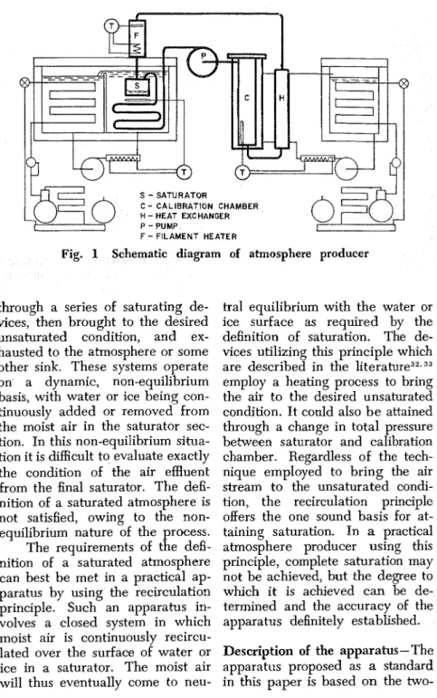
-
SATURATOR C-
CALIBRATION CHAMBER H - HEAT EXCHANGER P - PUMP F-
FILAMENT HEATERFig. 1 Schematic diagram
through a series of saturating de- vices, then brought to the desired unsaturated condition, and ex- hausted to the atmosphere or some other sink. These systems operate on a dynamic, non-equilibrium basis, with water or ice being con- tinuously added or removed from the moist air in the saturator sec- tion. In this non-equilibrium situa- tion it is difficult to evaluate exactly the condition of the air effluent from the final saturator. The defi- nition of a saturated atmosphere is not satisfied, owing to the non- equilibrium nature of the process. The requirements of the defi- nition of a saturated atmosphere can best be met in a practical ap- paratus by using the recirculation principle. Such an apparatus in- volves a closed system in which moist air is continuously recircu- lated over the surface of water or ice in a saturator. The moist air will thus eventually come to neu-
I of atmosphere producer
tral equilibrium with the water or ice surface as required by the definition of saturation. The de- vices utilizing this principle which
are described in the l i t e r a t ~ r e ~ ~ . ~ ~ employ a heating process to bring
the air to the desired unsaturated condition. I t conld also b e attained through a change in total pressure between saturator and calibration chamber. Regardless of the tech- nique employed to bring the air stream to the unsaturated condi- tion, the recirculation principle offers the one sound basis for at- taining saturation. In a practical atmosphere producer using this principle, complete saturation may not be achieved, but the degree to which it is achieved can be de- termined and the accuracy of the apparatus definitely established. Description of the apparatus-The apparatus proposed as a standard in this paper is based o n the two-
as shown in Fig. 2. The air first passes through a heat exchanger consisting of 40 ft of %-in. OD copper tubing and is discharged from the saturator nozzle parallel to the water surface and tangential to the walI of the saturator. The resultant vortex action in the satu- rator induces good mixing and serves as a centrifugal separator before the air leaves through a centrally located discharge port at top of the chamber. A slotted screen surrounding the exhaust port is a further guard against the possibility of droplet carry-over.
The saturator and its sur- rounding heat exchanger are im- mersed in a glycol-water bath which is continuously cooled to slightly below the desired tem-
Fig. 2 Saturator for pro- perature by a 1% hp single-stage posed humidity standard Refrigerant 22 condensing unit. A
1500-watt immersion heater, con- trolled by a sensitive on-off re- temperature principle, since this sistance bridge controller, raises lends itself more suitably to recir- the brine temperature to the de- culation of moist air. A schematic sired control point.
The air from the saturator diagram of the is shown passes over a bare nickel-chrome in Fig. 1. It consists essentially of a ~ o y wire heater where its
''#'
controlled-tem~erature liquid perat,, is raised to approximatelysources which maintain the sabra- the desired level, this heater be- tor section and calibration section ing operated by a proportionaI at different temperature levels. resistance bridge controller. The Heat exchangers located imme- air
hen
passes through an ex- diately before the saturator and tended surface heat exchanger to calibration chamber serve to bring a jacketed calibration chamber. the temperature of the moist air to Ethylene glycol-water brine from the required entrance conditions. a second controlled-
temperature The saturator - design is pat- liquid source is circulated through terned after that described by this heat exchanger and through We~ler.~"t is a cylindrical copper the jacket surrounding the calibra- chamber, 5 in. diam and 5 in. high, tion chamber in order to bring the filled with water to a level just air temperature to the desired below that of the air inlet nozzle, level.296 ASHRAE TRANSACTIONS Temperature control in this
section is accomplished using a re- heating principle similar to that employed in the saturator system. Rather than on-off control, a pro- ~ortional control system with de- rivative and integral action is used, having the sensing element located in the calibration chamber.
The calibration chamber con- sists of a jacketed copper cylinder, 4 in. ID and 28 in. long, shown schematically in Fig. 3. Access to this chamber is provided by a re- movable transparent plastics head which is bolted to the top of the chamber through a gasket seal. A sword arrangement secured to the head and extending into the cham- ber serves as a support for the
HYGROMETER
humidity elements under test. Pro- IN PLACE
vision is also made for the inser- tion of other humidity sensing de-
Fig. 3 Calibration chamber vices in the exit tube of the cham- with sword removed
ber.
The air circulation pump con-
sists of '?.%'' d i a ~ h r a g m - t y ~ e paint bridge. A calibrated copper re-
'pray 'peraCed in tan- sistance thermometer is used to dem. The Pumps are arranged to measure the air temperature in Operate 180 degrees Out of phase the calibration chamber. Pressure to reduce Pressure fluctuation. measurements in the calibration These pumps were found to be chamber and saturator are in&- only type available which satisfied cated by tube oil ma- the combined requirements of neg- nometers.
ligible leakage and contamination
in the desired flow range of 3 to 4 ge,fOmmce of the apparatus
-
cfm. Connections between the vari- calculation of he humidity of the OuS components of the air C ~ ~ C U - test atmosphere in the calibration
lation system are made with flexi- chamber is based on the assump- ble polyethylene pipe and tion that the moist air in the sys- clamps. tem is in neutral equilibrium with The temperature of the satura- the water surface in the saturator tor bath is measured using a tali- at the temperature indicated by brated platinum resistance ther- the platinum resistance thermome- mometer and precision Mueller ter. I t is further assumed that the
P~?OPOSED H U ~ I ~ D I T Y STANDARD BY C . E. TILL A N D G. 0. HANDEGORD 297 temperature indicated by the cop- ble difference in vapor pressure of per resistance thermometer repre- the test atmosphere provided by sents the temperature of the air- the fresh distilled water and that vapor mixture at any point in the provided by water that had been calibration chamber. Measure- in use for some time.
ments were therefore undertaken
to determine the extent to which (b) Planelless of the water surface
these assumptions were realized, -Observations were made of the and to evaluate the over-all accu- condition of the water surface
racy of the apparatus. under various air flow rates using a The extent to which the re- glass-walled saturator. At the de- quirements of the definition of sat- sired air flow rates of 3 to
5
cfm, uration are achieved is dependent the water surface was only slightly on the purity of the water, the disturbed and no agitation suffi- planeness of the water surface, the cient to cause droplet formation equality of the temperature of the occurred until much higher flow moist air and water surface, and rates were used. Since exbemely the equilibrium condition between small droplets would have to be the vapor component of the moist formed to introduce significant air mass and the water surface. errors, the requirement of plane- ness of the water surface was con- (a) Purity of the water-The purest sidered satisfied.water available at the laboratory
was triple distilled water. This was (c) Equality of the temperature of used as a standard against which moist air and water surface
-
The to compare water that had been transfer of heat to the saturator in use for some time in the atmos- from its outlet connection, by con- phere producer. The method em- duction or by radiation, is mini- ployed was a comparison of the mized in the design of the appara- readings of a sensitive electrolytic tus. The saturator is immersed to hygrometer when the atmosphere a depth of at least 3 in. in the producer had come to its steady- controlled temperature fluid and state condition, first with water in the interior is shielded from expo- the saturator that had been used sure to any outlet component for some time, then with fresh which is at a higher temperature triple-distilled water, all other con- than that of the bath.ditions being maintained constant The saturator heat exchanger The electrolytic hygrometer used was completely immersed in the was sensitive to changes in vapor bath and proved to be of ample pressure of less than 0.1 per cent. capacity to bring the air to the In some of the tests the water average bath temperature with the had been in use for approximately flow rates employed. Measure- a month; in others the water had ments with calibrated thermocou- been in use for only a few days. ples and a precision potentiometer In no case was there any detecta- indicated that, with 100 F differ-
298 ASHRAE TRANSACTIONS
ence between inlet air and satu- of the steady-state coadition the rator temperature, air entering the temperature readings were taken. saturator was within +- 0.01 F of The thermocouples were then re- the average bath temperature. calibrated.
A series of measurements was Table I provides four typical made of the temperature of the conditions through the full range water and of the air-vapor mass of relative humidities. The devia- above the surface of the water in tions shown are maximum devia- the saturator. Thirty-gage ther- tions. Case A represents an ex- mocouples, calibrated against a treme condition, corresponding to platinum resistance thermometer a relative humidity of about 4 per to -1-0.01 F, were used in conjunc- cent, which approaches the most tion with a precision potentiometer rigorous condition the saturator sensitive to temperature fluctua- heat exchanger encounters in prac- tions of less than 0.01 F. Five tice. Even at this extreme, the thennocouples were used: two average bath temperature, the wa- measured water temperature and ter temperature, and the tempera- three the temperature of the air- ture of the air-vapor mass agreed vapor mass at points above the to within 0.05 F. In the other three water surface as indicated in Fig. 2. cases the largest observed devia- The saturator bath tempera- tion was 0.02 F. Thus the tem- ture was measured with the plati- perature of the air-vapor mass n m resistance thermometer and over the water surface is substan- Mueller bridge. In each case the tially equal to the average tern- calibration chamber temperature perature of the saturator bath. was 70.0 F, the flow rate was 3.6 It was difEcult to make an ac-
cfrn, and the depth of the water in curate direct measurement of the
the saturator was 34 in. The pro- water surface temperature. Ther- cedure in each case was to cali- mojunction 2 was just under the brate the thermocouples against water surface and thermojunction the platinum resistance thermome- 3 was just above it. In no case was ter and then to place the h e r - there any evidence of a tempera- mocupIes in the saturato
period s d c i e n t for the
SPATIAL VARlA A B Saturator Bath Temperature F . . .
.
..
-2.22 f 0.06 36.50*
0.05 ~ h e r k o c o u ~ l e # Thermocouple # Thermocouple # Thermocouple Jf Thermocouple #of the air-vapor mass was substan- within the recirculation system; tially equai to the bulk tempera- (2) a mass exchange between the ture of the water. As there is no air-vapor mixture in the recircula- possibility of a net radiation ex- tion system and the ambient at- change with the surface, the sur- mosphere, caused by leakage.
(1) Moisture exchange-Aside from
the presence of an open liquid or solid water surface, the only ap- the vapor component of the air- preciable moisture source would vapor mixture and the water sur- be the presence of hygroscopic ma-
face
-
The moist air in the system terials. The recirculation system is is recirculated repeatedly over the up almost entirely of metals, water surface. The steady-state clear plastics, and polyethylene. condition of the vapor component The amount of moisture sorbed on must be that of neutral equilibrium these surfaces would be entirely with the water surface if there are negligible in with the no sources or sinks present in the magnitude of the air-vapor mass. recirculation system other than the Under steady-state there saturator. Any source or sink that is no source of liquid or solid wa- tends to change the relative pro- ter within the recirculation system portions of air and vapor in the other than the saturator itself. The air-vapr mixture tends to upset possibility of a serious moisture the neutral equilibrium condition sink exists only if the saturator is in the saturator. There are two operated at temperatures above possibilities: (1) a net exchange of the temperature of the room. Con- moisture between the air-vapor densation on certain of the recir- oisture sources culation system boundary surfaces the saturator, might occur. This effect limits the operation of the atmosphere pro- ducer to the ~roduction of atmos- pheres in wh'ch the dew-point is below the ambient temperature.ge
-
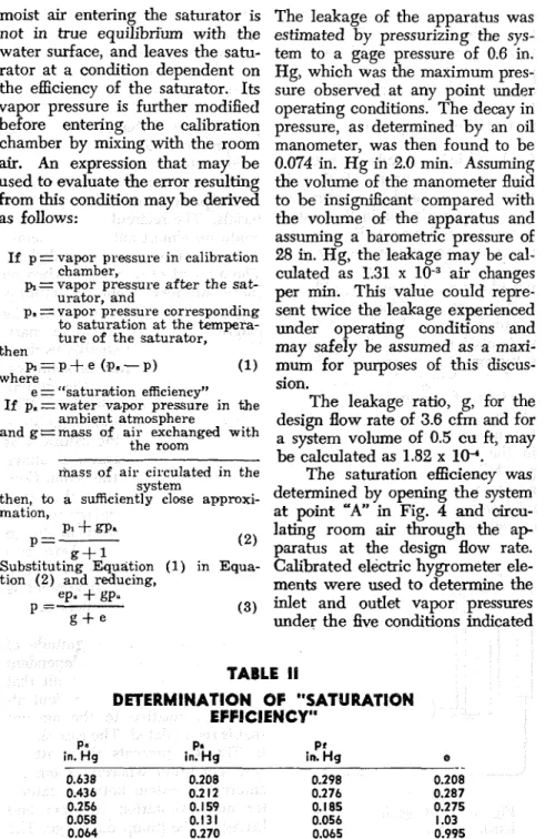
The magnitude of of leakage is dependent amount of moist air that ed with the ambient at- ative to the amount lated. The case shown epresents the most se- ition whereby room air enters the system between satura- tor and calibration chamber and leaves at the pump discharge. Themoist air entering the saturator is The leakage of the apparatus was not in true equilibrium with the estimated by pressurizing the sys- water surface, and leaves the satu- tem to a gage pressure of 0.6 in. rator at a condition dependent on Hg, which was the maximum pres- the efficiency of the saturator. Its sure observed at any point under vapor pressure is further modified operating conditions. The decay in before entering the calibration pressure, as determined by an oil chamber by mixing with the room manometer, was then found to be
air. An expression that may be 0.074 in. H g in 2.0 min. Assuming used to evaluate the error resulting the volume of the manometer fluid from this condition may b to be insignificant compared with as follows: the volume of the apparatus and assuming a barometric pressure of
~f p = vapor pressure in calibration 28 in. Hg, the leakage may be cal- chamber, culated as 1.31 x air changes
p,
=
vapor pressure after the sat-urator, and per min. This value could repre- p,
=
vapor pressure corresponding sent twice the leakage experiencedto saturation a t the tempera- under operating conditions and
ture of the saturator,
then may safely be assumed as a maxi- P I = P + ~ (pa-P) (I) mum for purposes of this discus-
where
e = "saturation efficiency" sion.
If p.= water vapor pressure in the The leakage ratio, g, for the ambient atmosphere design flow rate of 3.6 cfm and for
and g = m a s s of ail. exchanged with a system volume of 0.5 cu ft, may the room
be calculated as 1.82 x 10⁻¹.
&ass of a i r circulated in the The saturation efficiency was
system
then, to a sufficiently close approxi- 'pen% the 'ystem mation, at point "A" in Fig. 4 and circu-
PI f fa. lating room air through the a p
P =
g + l ( 2 ) paratus a t the design flow rate. Substituting Equation (1) in Equa- Calibrated electric hygrometer ele-
tion ( 2 ) and reducing, ments were used to determine the
eP*
+
gP.P = (3) inlet and outlet vapor pressures
6 + e under the five conditions indica
TABLE I1 DETERMINATION OF "SATURATION EFFICIENCY" P. P i in. Hg in. Hg e - - 0.638 0.208 0.298 0.208 0.43 6 0.212 0.276 0.287 0.256 0.1 59 0.1 85 0.275 0.058 0.131 0.056 1.03 0.064 0.270 0.065 0.995
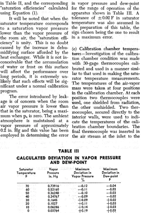
in Table 11, and the corresponding in vapor pressure and dew-point "saturation efficiencies" calculated for the range of operation of the using Equation (1). apparatus shown in Table 111. A It will be noted that when the, tolerance of 2 0.02 F in saturator saturator temperature corresponds temperature was also assumed in to a saturation vapor pressure the preparation of this table, the lower than the vapor pressure of sign ~ h o s e n being the one to result the room air, the "saturation effi- in a maximum error.
ciency" is unity. This is no doubt
caused by the increase in dehu- (e) Calibration chamber tempera- midlfylng surface ~ ~ f f ~ r d e d by the mes-Investigation of the calibra- heat exchanger. While it is not in- tion chamber condition was conceivable that the accumulation with 30-gage ~ e m o c o u p l e s Cali- of water or frost on this surface brated and used in a manner simi- will affect the performance over 1, to that used in the sah- long periods, it is extremely un- rator t e m p e r a b e meaurements. a e l ~ that such effects will be sig- temperatures of the air-vapor nificant under a normal calibration mass were taken at four positiOm program. in the calibration chamber. At each The error intr~duced by leak- position two thermocouples were age is of concern when the ps om used, one shielded from radiation,
air vapor pressure is lower than the unshielded. Two ther-
that in the saturator, being a maxi- mocouples, secured directly to fie mum when pa is zero. The ambient interior walls, were used to in&- atmosphere is maintained at a cate fie temperatures of the vapor Pressure of approximately bration chamber boundaries. The 0.2 in. Hg and this value has been find themocouple was inserted in termining the error the air stream at the inlet to the
TABLE llI
CALCULATED DEVIATION IN VAPOR PRESSURE AND DEW-POINT
Sa Vapor lmum Maximum
Temperature Pressure Deviation in Deviation in
F in. H g Vapor Pressure Dew-point
302 ASHRAE TRANSACTIONS heat exchanger. The positions of
the thermojunctions. are shown in Fig. 3.
The filament heater was found to cause a cyclical temperature variation in the air stream entering the heat exchanger. The amplitude was approximately t 0.4 F, and the period was approximately 10 sec. The maximum "droop" ob- sewed was in the order of 2 F when the saturator bath tempera- ture was varied through a range of temperatures corresponding to the full range of
at 70 F.
The spatial
temperature of the air-vapor mass in the calibration chamber and the variation in the temperature of the walls of the calibration chamber for a . 12-hour period of test are shown in Table IV. The copper resistance thermometer measuring the calibration chamber tempera- ture read 69.52
+
0.03 F during this period. The average tempera- ture of the air stream at the heat exchanger inlet varied from 68.7 to 70.3 F as the load on the system was varied by changing the satura-tor bath temperature. The cyclical variation was t 0.4 F. The toler- ances quoted in Table IV are maxi- mum deviations.
The results show that the spa- tial variation in the average tem- perature of the air-vapor mass were no worse than k0.02 F and the total fluctuation in temperature over the 12-hour period was 20.05 F at the maximum. The copper re- sistance thermometer measured the average temperature to an accu- racy within its rated sensitivity of 0.03 F.
(f) Over-all accuracy of the appa- ratus-The primary function of the atmosphere producer is in the cali- bration of electric hygrometer sensing elements in terms of rela- tive humidity. The maximum un- certainty in the values obtained are shown in Table V, based on the possible errors in vapor pressure taken from Table III and assuming an error of t 0.05 F in the calibra- tion chamber temperature.
The errors listed in Table
V
represent maximum values deter- mined using the worst possible
TABLE I V
CALIBRATION CHAMBER TEMPERATURES
Thermocouple Temperature
Position Details " F
Shielded from radiation Unshielded
Shielded from radiation Unshielded
Shielded from radiation Unshielded
Shielded from radiation Unshielded
W a l l temperature W a l l temperature
combination of errors. The prob- 3. The gravimetric hygrometer, as able error will be less for each case. the exception, although potentially These inaccuracies are a result of a fundamental standard, is of re- the effect of leakage and the pres- stricted use as a practical standard, ent practical limits of temperature and requires a constant atmosphere control and measurement, and are for its application. A A
caused any 4, An atmosphere producer, em- characteristic of the method. I t is ploying recirculation of moist air
that to in a system, provides a prac- the present be made tical fundamental standard for hu- with a view to the elimination of midity which is consistent, in prin- leakage and t' more precise ciple, with the definitions given by urement and conhol of the Report of the International ture. Joint Committee on Psychrometric
CONCLUSIONS
1. The definitions of the thermo-
dynamic properties of moist air given in the Final Report of the International Joint Committee on Psychrometric Data leave little scope for the establishment of a fundamental standard of humidity other than by the production of a standard atmosphere.
2. The definitions given in the Re- port are such that no practical form of humidity measuring instru- ment can be used to provide a fun- damental humidity standard. Such instruments, with one possible ex ception, must b e calibrated in terms of a standard atmosphere.
Data.
5.
The condition of the air-vapor mass in the recirculation system of the atmosphere producer described in this paper necessarily satisfies the definition of an atmosphere saturated a t the measured temper- ature T I a n d the measured total pressure P.,, within a small toler-i
ance. This tolerance arises from the practical limitations in tem- perature control and the practical limitations on the establishment of the neutral equilibrium condition. 6. In contrast to those systems that do not involve recirculation, the limitations on the knowledge of the condition of the air-vapor mix- ture in this atmosphere producer
TABLE V
MAXIMUM UNCERTAINTY I N THE RELATIVE HUMIDBTY EXPRESSED IN PEW CENT W.H.
Temperature. Relative H u m i d i t y
304 ASHRAE TRANSACTIONS
may be precisely evaluated. The sity too large, complex, and expen- maximum uncertainty in the vapor sive for acceptance as a standard pressure of the test atmosphere is piece of equipment in all labora- in the order of 0.1 per cent in the tories. I t is to be hoped, however, temperature range froin 0 to 70 F . that the provision of one such ap- The maximum uncertainty in the paratus in the National Research dew-point is in the order of 0.03 F Council Laboratories will satisfy in the same temperature range. most of the needs for a standard- The maximuin uncertainty in- rela- ization facility in Canada.
tive humidity is, on the average,
0.2 per cent R.H. through the full ACKNOWLEDGMENTS
range of the relative humidities a t The work reported in
paper
temperatures from lo to 70F. was done by the senior author
7. The range of humidities that while on the staff of the Prairie
the atmosphere producer is capa- ~ ~station of the ~i~ of ~ i ~ ~ ~ l
ble of producing is limited in the ~ ~ i l d i ~ ~ Research, National Re-
Present arrangement to dew-points search Council, at Saskatoon, Can-
between -20 and 70 F. The lower ada. ~h~ paper is based on a
limit is fixed by the capacity thesis prepared by the senior au-
the saturator bath refrigeration thor under D ~ . B, ~ 7 . currie of the
unit, and the upper limit is fixed Department of Physics and sub-
the ambient The mitted to the Faculty of Graduate lower limit of the dry-bulb tem- Studies, University of Saskatche-
Perahre is lo F, set the wan, in partial fulfillment of the
ity of the air-temperature bath re- requirements for the degree of
frigeration unit. The upper limit ~~~t~~ of science.
is presumably fixed only by the The authors express their ap-
boiling point the gl~cO1-water preciation to D. G. Cole and other
mixture. members of the staff of the Prairie
8. Although the atmosphere pro- Regional Station for the valued as- ducer was developed for a specific sistance given them in the design
purpose in studies in the field of and construction of the apparatus.
building research, it provides a reference standard of' humidity
which has much broader applica- REFERENCES
tion. There is no doubt that the 1. Standardization of Thermodynzmic Proper- ties o f Moist Air,--by J . A. CoR, ASHVE
accurate calibration of humidity- Transnctionr. VOI 35. 1943 P 459.
2. Heating. Ventilating and A i r Cond~tioning
sensing instr~ments would be of Guide, 1958 D. 25. (Amerlcan Society of
Heating a n d A i r Conditioning Engineers).
value to research workers in other 3 . Introduction to T h e r m d y n a r n ~ c s , the
fields, and the availability of a Kinotic Mechanics. by rheoi-y of F W . Sears. Addison-Wesley Gases, a n d Statistical
standardization facility would be Publiihina Company, 1933, P. 7-9.
4. Accurate Deteimination or Dewpoirta. b y
useful to any investigator con- A. W. Hixron and G. E. White. Industrial
Engineerine Chemistry, Analytical Edition.
ceriled with humidity measure- VOI 10. 1938. 1, 2 8 5 .
5 . Dew-point Hyerometer f o r Use n t Low
ment. An atmosphere producer of Tempetatures. by C. A . W I ~ ~ I ~ I . Cxnadlan
6. Moisture Measurement with tin Electronic
Dewpoint Indicator. by V. E. Soumi. Instru- ments. Vol. 21. 1948, p. 1'78.
7 Improved Electronic Devzpoint Hygrometer,
by E. W. Barrett a n d L. R. Herndon, Journal of Meteorolom, Vol. 8. 1951. p. 4C-51
3. Further I m ~ r o v e m e n t s in the Electronic D o w w ' n t Hygrometer. bv E. W. Rsrrett. R
L. Slater nnd K. E. Newton. Journal of Metao~mlow. Vol. 12. August 1955. p. 308.
9. Illinois T e s t i n s Lnboratorics D e w ~ o l n t Indi- a t o r . Instruments. Vol. 19, 1946. p. 278.
10. Industrial Humidity In=truments, bv M. F. Behar. Instruments. Vol. 3, 1930. p. 549, 605,
P C O
" V d .
11. Resistance Thermometers for the Memure-
ment of Relative Humidity o r Small Temnera- t u r e Differences, by D. C. Rase, Canadian Journal of b e a r c h . Vol 5. 1911. p. 156.
12. Determination of Relative Hilmidities by
Means .of Thermocowles, by J. G. Lannina. Indu-rt.?al and EnRineerinp Chemistry. Ana- lytical &lition. Vol. .4. 1932, p. 286.
13. Thin-Film Psych'.ometer for Measuring Relative Humidity In Small S p a c e , by W. A.
W ~ n k and J. A. Van Den Akker. TAPPI, Technical Section. Vol. 39. September 3956,
p. 647.
14. CbnstantFRed All l'en.p~rnture Wet Bulb,
by S. M. Henderson, Agrtcultural Engineering,
October 1952. g. 644.
15. Construction and Use of a Thermoelectric Psychrometer, by C. k e n z e n J r . Tempera- t-Its Mavsurement a n d Control in S a e n c e and Industry, American Institute of Physics,
1341. P. 660.
16. Psychromebry in the Frost Zone. by D. D.
Wile. R e f r ~ g m a t i n g Engineering, Vol. 48. 1944, p. 291.
17. Theory of the Psychrometer. by J. H. Arnold, Physlce, Vol. 4. 1933. p. 256. 334. 18. Effect of Radiation on Psychrometer h d -
inga, by D. Dropkin, Cornell University Engi- neering kkperimental Station, Bulletin No.
21. Tilting Hygrometer: a New Form of Absorpt~on Hygrometer, by H . G. Mayo and A. M. Tyndall. Proceedmg! of Physical Society London. Vol 24. 1981-22. n. 67. . -
22 Studies with t h e Condensation Hygrometer
by' T. Okada a n d M. T a i n u ~ a . proceedings Imperial Academy. Tokyo. Vol. 16. 1940. p.
141 and 2C8.
23. Water &ntent of Saturated Air a t Tem-
peratlues u p to 100°C, by J. H. Awherry, Yroceedinss Physicrrl Society London, Vol. 44,
1932. p. 143.
24. Divided Flow Type, Low Temp?rature
Humidity Test A p p - d m , by A. Wexler, Jour- nal of Research. National Bureau of Stand- ard% Vol. 40, 1948, p. 479.
25. Two Pressure Humidity Atmosnhere Pro-
d u c ~ r , by R. S. Feizal and E. J. Arndur, Minnexpolis Honeywell Research Regod
QR2998-R1.
26. Supplying Atmospheres of Known Humid-
ity, by A. C. Walker, Bell Laboratory Record VII. 1933. p. 169.
27. Investigation o n Absorntion Hygrometers
a t Low Temperatures, by E. Gluckauf, Pro- ceedings Physical Society London, Vol. 59,
19-17 p 344
28. &arat;s f o r Producing Air of Con- trolled Relative Humidlty t o r Hygrometer Calibration a n d T a s t ~ n g by L. A. Cram, Jour- nal of Scientific Itwtruments, Vol. 33, 1956,
P. 273.
29. Measurement of Water in Gases by Elec- ~ r i c a l Conduct~on i n a Film of Hygroxoplc Material nnd t h e Use of P r m u r e Changes in Calibratiom. bv E R. Weaver a n d R. Riley. Journal of. &&oh, National Bureau of Standards. Vol. 40, 1948, D. 169.
30. Electrical Measurement of W a t e r Vnpour
with a Hygroscopic Film, by E. R. Wenrer. Analytical Chemistlr. Vol. 23. 195,l. D. 1076.
Y1. ~ r - u r e - ~ u m i d % y Apparntw, by A. Wex- ler and R. D. Damels. Journal of Resemch. National Burau of Standards. Nov. 48, 1952,
26 1939. P. 268.
19: Review of Existing Psychrometric Data. i n 32. Equipment f o r Conditioning Materials a t
Relation to Practical Engineering Problems, Constant Humidities and n t Elevated Tempera- by W. H. Carrier nnd C . 0. Mackey. A.S.M.E. ture, by J. G. Wiegeriiik, Journal of Research, Transactions. Vol. 59. 1937. p. 32 nnd 528. Nntlonal Bureau of Stnndnrds. Vol. 24. 1910.
20 Devlation of t h e Actual Wet Bulb Tempsra- g. 639.
ture from the Temnerature of Adiabatic 33. R e c i r ~ u l a t i n ~ Appnratus f o r T e s t i n g Hy- Saturation, by D. Dropkin. b r n e l l Umversity Kromcters, by A. Wexler. Journal of Research.
Engineering Expenmental Statlon. Bulletin National Bureau of Standarcis. Vol. 45, 1950. No. 23. 1936. P. 357.
DISCUSSION
E. J. AMDUR, Minneapolis. Minn. (Written): Minneapolis Honeywell Regulator Company. While electrical sensors of the Dunmore type This instrumentl, has been rather thoroughly are the most sensit~ve and precise of availabl'e investigated a n d tested by continuous use. A hygrometric dev~ces, in certain types of re- similar model was supplied to the U.S. Signal search it is desirable to calibrate these sensors Corps a t Fort Monmouth, N. J. in 1957. It is before and after a test procedure. The authors this type of atmosphere producer which we describe a two temperature calibration device feel to be a candidate primary standard of which is relatively inexpensive to construct, relative humidity. Experience with these de- and which is probably sufficiently precise for vices as well as with a two temperature the type of work which it wffl be called upon ahnosphere producer affect the comments to do. It is, however, ditacult to accept the given on the following page.
device described as a "fundamental" or
"primary" standard of relative humidity, or 1 E. J. Amdur. The Research Center Two
even a s the best "practical" standard device. Pressure Ahnosphere Producer, Minnen 011s I n I 9 5 5 a two pressure atmosphere pro- The Minneapolis-Honeywell Regulator 8om: ducer was built a t the Research Center of the pany, January 16, 1956.
ASHRAE TRANSACTIONS
To summarize the objectlolls to this paper and the device it describes:
1. The two temperature atmosphere
producer does not conform to the require- ments for a fundamental standard of relative humidity because the relative humidity cannot be directly calculated from phys'ical measure- ments. One does not utilize only the two temperature measurements taken but must accept vapor pressure tables as intermediary.
2. While gravimetric measurements seem to confirm the Goff and Gratch tables a t tem- peratures above freezing, determillations in our laboratory indicate a fairly constant deviation of 1.57 below 32 F, the actual vapor pres-
sure va?ues being larger than the tabulated values.00 As a practical standard the two tem- perature atmosphere producer is probably satisfactory when used with test chamber and saturator temperatures both above freezing, and wlth l ~ t t l e error if both temperatures are below 32 F. When tkie test chamber is above the freezing pomt and the saturator is below it, the posslble enor may be 1.5v0 rh from this
source. A program of precise gravirnetric evaluation of below freezmg vapor pressure tables appears necessary in order to remove this ambiguity.
3. I t is true that absolute, primary, or fundamental standards d o not by definition require calibration. Nevertheless, it is essential
that such standards be tested against alter- native primary standards. Whde the physical theory which forms the basis for the stand- ard may be impeccable, the apparatus and operations requued to use this theory fre- quently are less so.
The questlon is which alternative primary standard one is to use. It is di8icult to avoid the use of the gravimetric determination of the moisture content in a volume of air. I t is the only alternative method which may be applied wlth sufficient precision to constitute a n adequate test of a candidate prlmary standard method in the humidity field.
I t must be recognized that the gravirnetric procedure is an analytical method of determin- ing the vapor density (weight per unit volume) rather than vapor pressure, and relative humidity values calculated from vapor density measurements may d a e r slightly from those obtained from an atmosphere producer operating on a vapor pressure prmciple. The gravimetnc method itself is, as the authors mdicate, not nn easy procedure. It is time consuming and requires a high standard of manipulation d precise results are to he ob- tamed. Nevertheless, it is neces'sary to resort to this procedure before the validity of the two temperature atmosphere producer m a y be admitted.
O 0 The Goff and Gratch tables give values
for the vapor pressure of ice below 32 F. The values of the vapor pressure of water below
32 F are higher, and the deviation becomes
greater at lower temperatures. Values deter- mined at the Minneapolis-Honeywell labora- tones he between those for ice and water. about 1.5% above those for ice.
4. hlessrs. Tdl and Handegord devote some effort to arguments that there r\ some m e r ~ t m the type of saturation obtained in
thelr recirculation apparatus as compared to that achieved m a contmuous flow saturator. Tliese arguments appa~ently result from a confus~on between their device and a static equil~brium system. It can be shown that thew system ls rn fact no d a e r e n t in behavior from a continuous saturator having a great number of evaporators except that some in and out leakage occurs on each trip around the ap- paratus. This IS less likely to occur with the
straight lme or continuous device. Actually, n e ~ t h e r of these methods, both approachlug
saturation by evaporation of water mto the
a u , is as satisfactory as the method used in the Honeywell device according to our test results. I n this apparatus saturated alr is cooled to the desired temperature, both heat and molsture bemg simultaneously removed.
5. I n addition to the above points a
purely practical objection exists to the TiU device if operated as descrlbed. T h e passage of
3 cfm of a u through tubes of the slze in-
dicated will result in a fractional air pressure loss of some n ~ a g n ~ t u d e between the saturator and the test chamber. This change in pressure will introduce an error in the relative humidlty calculation. I t may be taken into considera- t ~ o n in the calculation If the pressure drop is
measured, but apparently Messrs. Tdl and Handegord have not done so.
6, The time response of the device ha^ not been reported and should b e quite long as compared to that of the two pressure system. A slowly respondmg device tends to be used less frequently because its use is tedlous. One avoids investigations whlch one might other- wise undertake. Whlle a slow response rate does not affect the valld~ty of the apparatus ~t does therefore tend to affect the amount and quallty of the work of a laboratory.
An ideal mstnunent should be accurate, easy to use and r a p ~ d m response. The two pressure devlce appears to b e superior on these counts to the Tdl and Handegord ap- paratus. T h e two pressure device is more ex- penslve to construct, although this mlght not be true on the basls of work output cipacity. Persons contemplating the construction of an atmosphere producer should also coiisider the two pressure principle seriously m the hght of their particular requuements.
CLOSURE BY AUTHORS TILL and HANDEGORD: The authors wish to thank Dr. Amdur for his comments on their paper and would also like to acknowledge the co-operation extended to them in the past by Dr. Amdur and his colleague, Mr. H. Lofgxen. of the Applied Research Divlsion of Mmneapolis-Honeywell. Thclr private comments and suggestions re- gardlng humidity instrumentation have been of considerable assistance in planning research in this field a t Saskatoon.
Dr. Amdur hos ralsed several objemons to the paper and to the acceptance of a two temperature recuculatmg apparatus of the type descrlbed as a hum~dlty standard. He suggests